Elektroda.com
Elektroda.com
X
This content has been translated flag-pl » flag-en View the original version here.
  • A simple Tesla music coil
    Hello
    I've always wanted to build a musical tesla coil, but I was overwhelmed by the complexity of the design schematics found on the internet. Some time ago I found a schematic of a single transistor based coil and decided to improve it so that it could play sound. I decided to share the project so that others could make such a simple coil.

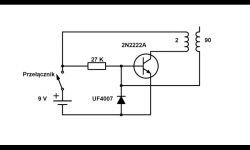
    Here is the diagram I found:
    A simple Tesla music coil

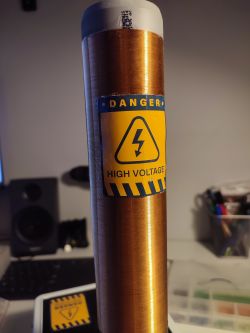
    The effect of her work was poor, no spark, only the fluorescent lamps were getting closer to light. I increased the number of windings to 5 on the primary (I made them from a 1.5 mm? cable ;) and around 1000 on the primary. There are 25 cm of windings with 0.25 mm diameter wire on a 5 cm diameter PVC pipe. After this procedure, the spark was immediately bigger, but a new problem appeared, the transistor did not last a long time and soon it fell. I experimented with many transistors and got a good result using the BD239. The transistor burnout problem was rare, but I wanted to eliminate it completely. It was helpful to replace the semiconductor diode connected in reverse to the base of the transistor with the LED - and attention, specifically the yellow one - and the insertion of a second transistor. Due to the fact that these transistors have more power, I increased the voltage of the system to 30 V, increasing the power of the coil to about 30 W (value read from the service power supply). I suspect that the tension can be increased a little more.
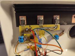
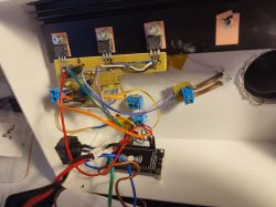
    The next step was to make the coil play. I used ESP8266 (it was handy, and I had code for arduino on the disk that plays simple tunes). ESP generates a square wave with a given frequency, which controls the unipolar transistor (2N7000), short-circuiting the bases of the transistors controlling the coil to ground. In this way, we managed to get a nice and loud sound from the coil.

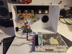
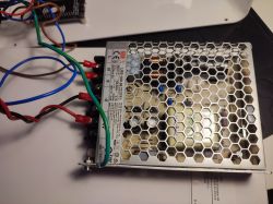
    Finally, I made a casing from some IKEA box that happened to be at home. As a power supply I used a 36 V impulse power supply (LRS-100-36, I had it from some electro-scrap that I got as a "gift" for parts), I reduced its voltage to 30 V with the potentiometer on it.

    I know that the scheme has some shortcomings, it was just created as much as my knowledge allowed, there is definitely something to be improved in it. It is as follows:
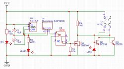
    A simple Tesla music coil

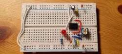
    I soldered everything temporarily on a universal board, there are plans to make a printed circuit board.
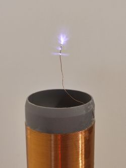
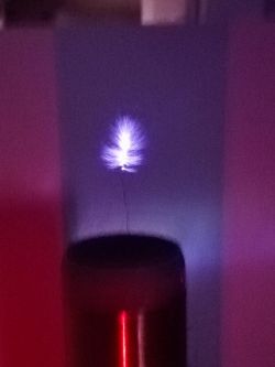
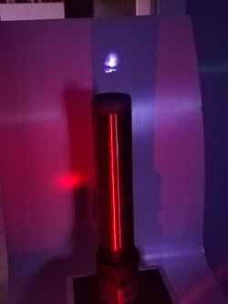
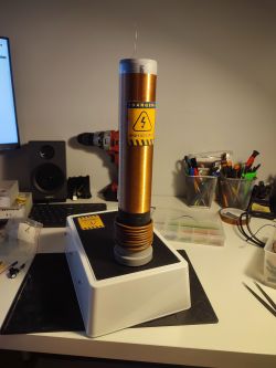
    Unfortunately, I didn't take photos during the creation, but I put in those with the coil ready.
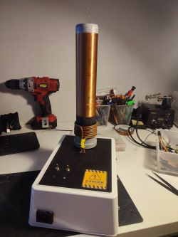
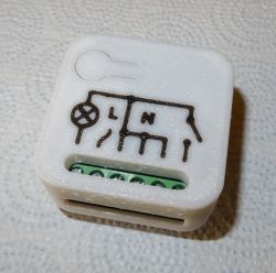
    A simple Tesla music coil A simple Tesla music coil
    A simple Tesla music coil A simple Tesla music coil
    A simple Tesla music coil A simple Tesla music coil
    A simple Tesla music coil A simple Tesla music coil A simple Tesla music coil

    1st movie:


    Program code for ESP8266 (written in Arduino IDE) I attach to the topic. ESP provides a page on the local network where you can select a track to play. I add a second program that works immediately after startup (it does not connect via Wi-Fi, only plays one track in a circle).
    Regards

    PS.
    It should be noted that the Tesla transformer generates a high voltage of several kilovolts, so be especially careful when working!

    Cool? Ranking DIY
    Do you have a problem with Arduino? Ask question. Visit our forum Arduino.
    About Author
    patrykkurzejago
    Level 3  
    Offline 
    patrykkurzejago wrote 7 posts with rating 31. Been with us since 2022 year.
  • #2
    bambus94
    Level 32  
    Have you checked the frequency of work? As it goes in hundreds of kHz or even MHz, you could try something similar to a class D amplifier and then even normal mp3 would play. Kind of like my HFVTTC link below in featured.
    You already have experience, now SSTC halfway or rich and DRSSTC.
  • #3
    patrykkurzejago
    Level 3  
    bambus94 wrote:
    Have you checked the frequency of work?

    Unfortunately, I do not have an oscilloscope or even a multimeter with frequency measurement. I also do not know how to check or calculate this frequency in another way :( Does such a coil emit radio frequency at its operating frequency? Because if so, I have rtl-sdr that I could search for this frequency.

    bambus94 wrote:
    You already have experience, now SSTC halfway or rich and DRSSTC.

    I found that building this only spurred me to build something bigger. It's very addictive, so I'm thinking about it :D
  • #4
    bambus94
    Level 32  
    Yes, the Tesla coil is essentially a radio transmitter.
    A well-tuned one should generate radio waves with a length equal to the length of the wire on the secondary winding. A less tuned one will transmit at the frequency depending on the inductance and capacitance of the secondary winding.
    If the SDR catches you a few MHz range, then maybe you can catch it. And if not, maybe you should make an Up-Converter to SDR? I have one that raises the frequencies by 80 MHz and can pick up stations from several dozen kHz.
  • #5
    patrykkurzejago
    Level 3  
    Then let me look for that frequency in a moment. I have an SDR with the R820T2 chip and it reaches up to 1864 MHz.
  • #6
    bambus94
    Level 32  
    Rather, you have to look at the lower range, that is, a single MHz. Even if you catch something, you cannot be 100% sure of this frequency, because it may be one of the next harmonics.
  • #7
    patrykkurzejago
    Level 3  
    I rummaged through the manual and it turned out that my SDR ranges from 0.1 MHz to 1.7 GHz (it was enough to change the settings). The coil emits a strong wave at 1.037 MHz, if it's playing a song, I have modulation and can hear music from the radio.
  • #8
    Janusz_kk
    Level 36  
    bambus94 wrote:
    A well-tuned one should generate radio waves with a length equal to the length of the wire on the secondary winding.

    Not true, the resonant circuit is inductance and capacitance, not the length of the wire.
  • #9
    bambus94
    Level 32  
    Yes, but a well-calculated Tesla coil has a resonant frequency equal to that of a wire-length wavelength on the secondary winding. This is why toruses are used to vary the resonant frequency to tune this frequency to the length of the wire.
  • #10
    Janusz_kk
    Level 36  
    bambus94 wrote:
    Yes, but a well-counted Tesla coil has a resonant frequency

    equal to inductance and inter-winding capacitance.

    bambus94 wrote:
    a resonant frequency equal to that of a wire-length wavelength on the secondary winding.

    that someone also wanted to look for such a relationship :) normally no one is concerned with such dependencies.
    Anyway, the author has too high a frequency and that is why the transistors heat up so much for him, more energy goes into heat than into a spark, therefore the remarks about the danger are thought over because at the currents offered by the coil it will not hurt anyone.
  • #11
    bambus94
    Level 32  
    Janusz_kk wrote:
    that someone also wanted to look for such a relationship :) normally no one is concerned with such dependencies.

    Well, someone found it and everyone who wants to have good results applies to this dependence.
  • #12
    zulugula
    Level 19  
    Every radio amateur will tell you that the best amplifier is the antenna, and by choosing its dimensions and the length of the wire, you tune it.
    And wasn't the length of the wire 1/4 or 3/4 of the length?
  • #13
    bambus94
    Level 32  
    From what I remember it was 1 or 1/2 wavelength. I have to look for an email from a man who did something about 40 cm of arc on VTTV on GU81.
  • #14
    patrykkurzejago
    Level 3  
    Janusz_kk wrote:
    Anyway, the author's frequency is too high and that is why the transistors heat up so much for him, more energy goes into heat than into a spark, so the remarks about the danger are thought over because at the currents offered by the coil it will not hurt anyone.

    If someone has a pacemaker, a heart defect, a disturbed potassium-sodium balance, or some other heart conductivity problem, such a coil is very dangerous. At best, a healthy person can burn, but I still recommend caution. It is better to be careful than the effect of your work from the "top".

    When it comes to electronic devices at home, I was approaching the coil with a sports wristband or the phone and nothing happened, but I have Google Nest speakers at home and after activating the coil, even those in the next room go down and get louder at random moments.

    zulugula wrote:
    And was the length of the wire not 1/4 or 3/4 of the length?
    bambus94 wrote:
    From what I remember it was 1 or 1/2 wavelength.

    I was building a GP antenna with a 3/4 wavelength radiator and building a 1/2 wavelength half-wave dipole, so you both might be right. Both structures were built on the basis of information from the club's hams, and both worked properly.

    Janusz_kk wrote:
    Anyway, the author's frequency is too high and that's why the transistors are so hot for him.

    At the moment, by manipulating the primary winding (mainly up and down), it was possible to obtain the greatest spark and minimum heating of the transistors. The heatsink that I used at the moment is greatly exaggerated, after 10 minutes of operation, the coil is 35 degrees (at 23 degrees at home). In this design, the frequency depends on the LC circuit made of the secondary winding and the capacitance between the windings.
  • #15
    Janusz_kk
    Level 36  
    patrykkurzejago wrote:
    If someone has a pacemaker, heart defects, a disturbed potassium-sodium balance or any other problems with the conductivity in the heart, such a coil is very dangerous

    Epidermis, read how much it is at 1 MHz.

    zulugula wrote:
    Every radio amateur will tell you that the best amplifier is the antenna, and by choosing its dimensions and the length of the wire, you tune it.

    But the coil is not an antenna.
  • #16
    rosomak19
    Level 22  
    I would be more tempted to use the term Tesla's generator or transformer, not "coil"; Second thing, the Tesla generator is tuned with the primary winding, not the secondary one. The third thing, the torus, is the capacitor (or more precisely, one of its facings, because the other is Earth), which is part of the resonant circuit of the secondary circuit. Its capacity is calculated on this basis, then its physical dimensions are calculated. As for the primary winding, it is always a few more turns than calculated. With the alligator clip you can change the inductance of the winding in order to best match the resonant frequency of the primary circuit to the secondary one. In a classic generator with a trafa from 10 kV / 50 mA neon, after calculating the coils and capacitor, adjusting on the primary one, I achieved discharges into the air at a distance of 1 meter! With such a low power of the supply transformer, it proves the perfect alignment of the circuits. Finally, I would like to add that the secondary winding is basically a quarter-wave dipole antenna.
  • #17
    patrykkurzejago
    Level 3  
    Janusz_kk wrote:
    Epidermis, read how much it is at 1 MHz.

    What about the electromagnetic field? It seems to me that the starter is shielded in some way and the risk is minimal, but I wonder if anyone knows anything more about it. I even remember in high school, before the teacher started the electrostatic machine, he asked if anyone had a pacemaker, on the other hand, clothing a sweater could be dangerous then. I know personally a situation in which an electrostatic discharge from a TV picture tube killed a woman with a cardiac arrhythmia. However, I am aware that this case was quite "exotic" and rare.
  • #18
    zulugula
    Level 19  
    As @ rosomak19 wrote, it can be considered a quarter-wave plate, but for proper resonance it needs to be tuned with a suitable capacitor, e.g. a torus. Finally, tune the resonance in the primary circuit.
    As for heart pacemakers, while the epidermal effect is in favor, such a strong electromagnetic field, especially in systems with a magneto, is not so negligible.
  • #19
    rosomak19
    Level 22  
    I do not know about your musical Tesla, but with my classic one, the field was so strong that the fluorescent lamp in my hand shone from a long distance. I do not know about the starter, but the phone and camera survived filming the discharges. The problem here is the very significant ozone release, and it is quite significant.
  • #20
    bambus94
    Level 32  
    I would be more afraid of nitrogen oxides than ozone.
    It was one of the first industrial methods of producing nitrogen oxides and then nitric acid. An electric arc in the air, later refined by the addition of magnets, resulted in a spinning electric arc in the air. Interestingly, this technology was developed and effective by a Pole, but I do not remember the name.
  • #21
    patrykkurzejago
    Level 3  
    It fires fluorescent lamps from several dozen centimeters, Google speakers are standing in the next room and they are freaking out. I approached the transformer with the smart band on purpose (I forgot about it), the phone was in my other hand and nothing happened. As for ozone, it is noticeable, but not an intense smell. About two years ago I had a neighbor who dealt with ozonation and I was in a room where the ozone concentration was at an acceptable level (measured with a meter), and the smell was very intense and left such a strange feeling in the nose. So the ozone itself here doesn't seem to be a threat.

    As for nitrogen oxides, I put a moistened litmus paper close to the arc, after a while it turned red, so it actually arises.

    bambus94 wrote:
    From what I remember it was 1 or 1/2 wavelength. I have to look for an email from a man who did something about 40 cm of arc on VTTV on GU81.

    25 cm of 5 cm diameter windings are wound with 0.25 mm wire. So the length of the wire used is about 157 m (the windings are tight, but the 7 m can be less) of the wire, the 1 MHz wave is 300 m long. It would turn out that the length of the secondary winding corresponds to 1/2 of the wavelength . I can be wrong of course. The secondary winding is an LC circuit and logic dictates that this is just a coincidence.
  • #22
    _lazor_
    Moderator of Designing
    As such a topic gives a warning:

    The epidermal effect does not protect against infection:
    https://en.wikipedia.org/wiki/Tesla_coil#Skin_effect_myth

    The shock effect also does not feel above a certain frequency because our system will not react:
    http://amasci.com/tesla/teslafaq.html#two

    Such a toy does not offend too much because it does not carry a lot of energy at the exit. Please fight the myth of the anti-paralytic epidermal effect!
  • #23
    rosomak19
    Level 22  
    _lazor_ wrote:
    Such a toy does not offend too much because it does not carry a lot of energy at the exit.

    I would argue a bit, because whether it "tickles" someone or "potelepie" depends on several factors, including individual ones. If I were the moderator, I would not write such assurances, encouraging young inexperienced amateurs of high tension to try, or to "kick" hard. Each toy can hurt you under favorable conditions.
  • #24
    Janusz_kk
    Level 36  
    _lazor_ wrote:
    The epidermal effect does not protect against infection:

    I did not write that it only reduces significantly. For sure the effect is different for 50 Hz and different for 1 MHz.

    _lazor_ wrote:
    Such a toy does not offend too much because it does not carry a lot of energy at the exit.

    After all, I wrote the same.
    Janusz_kk wrote:
    therefore, the remarks about the danger are imaginary, because at the currents that the coil offers, it will not hurt anyone.

    _lazor_ wrote:
    Please fight the myth of the anti-paralytic epidermal effect!

    Maybe start with yourself? :)
    Look at what you answer and what the power range is.
  • #25
    _lazor_
    Moderator of Designing
    rosomak19 wrote:
    I would argue a bit, because whether it "tickles" someone or "potelepie" depends on several factors, including individual ones. If I were the moderator, I would not write such assurances, encouraging young inexperienced amateurs of high tension to try or "kick". Because every toy can hurt you under favorable conditions.


    The myth of the epidermal effect protecting a magical beginner who doesn't even have an oscilloscope is even more dangerous. Especially since they somehow assume that there are single MHz where the resonant frequency is often several hundred kHz.
    Maybe it will also specify that I did not mean that every Tesla transformer has low energy at the output and is therefore safe, I mean that it is not the epidermal effect that protects against electric shock. It is impossible to compare the phenomenon of the epidermal effect for the environment where there are two spaces with different parameters (electric conduit and air) to the environment with a very large amount of space with different parameters. And the fact that they called it the epidermal effect, it never meant that the current was flowing over the human skin ...
  • #26
    rosomak19
    Level 22  
    Let me say on my example, my classic Tesla had a resonant frequency of 161.6 kHz. Fortunately, while playing with the fluorescent lamp, I reduced the power of the power supply, despite this I inadvertently brought it too close to the torus and the discharge went to the fluorescent lamp, thus to me. Let me put it this way, I felt like having fun in a moment. I don't know what would happen if it was at full power.
  • #27
    Janusz_kk
    Level 36  
    rosomak19 wrote:
    Let me put it this way, my desire for a moment changed to such games,

    What were you counting on? that he will only 'stroke' you :)
    Electrocution always has some effects, but the fact that they do not infect internal organs is much less dangerous than 50 Hz or DC, but that does not mean that they are pleasant.
  • #28
    rosomak19
    Level 22  
    I wasn't counting on anything except the effect of the fluorescent lamp lighting up under the influence of a strong electromagnetic field, but I got too close.
  • #29
    _lazor_
    Moderator of Designing
    rosomak19 wrote:
    I was not counting on anything except the effect of the fluorescent lamp lighting up under the influence of a strong electromagnetic field, but I got too close


    At 161 kHz, we are talking about an electromagnetic field, but a close one (wavelength about 1800 m), and due to the fact that the current flowed negligibly, it was under the influence of a strong electric field.
  • #30
    KJ
    Level 31  
    The resonance with these winding parameters and without any toroid should be around 350kHz. The epidermal effect vs tesla - yes, everyone writes about it everywhere is only 1 small ... okay 2 quite big problems with this phenomenon in the context of current flow through tissues. First of all, the human body is not a homogeneous conductor, secondly, it is largely an ionic conductor, which roughly means that the epidermal effect is not manifested here by the current flow over the skin as it is usually described. Could it be dangerous? It depends on the scale - such a tessel will not harm anyone healthy in an accidental contact with the discharge, but this size DRSSTC where the instantaneous currents in the discharge calmly reach several A? I would think twice. The classic Tesla coil in the context of the epidermal effect has one more problem - in the discharge current there is almost always a 50 / 100Hz component and in the event of a breakdown between the primary and secondary its value will reach dangerous levels. Freaking electronic devices further away from the Tesla (e.g. in another room) usually indicates that it is not properly grounded. The problem is the greater the higher the resonant frequency, because the resistance, or more precisely, the impedance of a typical earthing circuit in a classic electrical installation for high frequencies, usually differs significantly from what results from the measurements - after all, electrical installations are adapted and standardized for 50Hz. As for the dependence of the wavelength equal to the length of the wire - I hear first, but it could explain a lot - out of curiosity, I will check what it looks like in my designs.