logo elektroda
logo elektroda
X
logo elektroda

Zmai-90 with CBU module does not start after flashing. Could not pick up GPIO.

ghost198922 6720 51
ADVERTISEMENT
  • #1 20250220
    ghost198922
    Level 3  
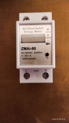
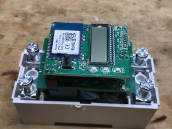
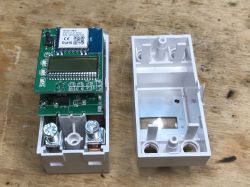
    Hello. Recently received new counters Zmai-90 with CBU module.

    When flashing the module, OpenBK was unable to start the module. Could not pick up pins (GPIO).
    An open access point is created, but no data appears on the LCD screen of the counter.

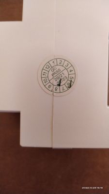
    All Zmai bought 09.2022, produced 06.2022.
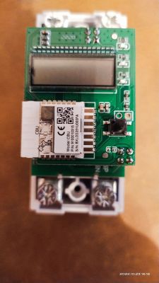
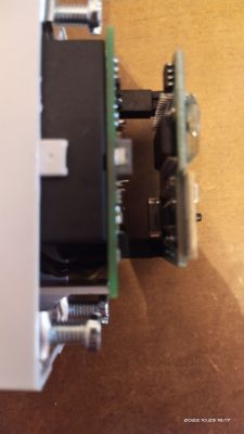
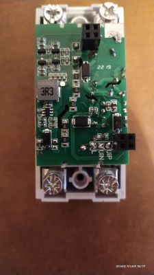
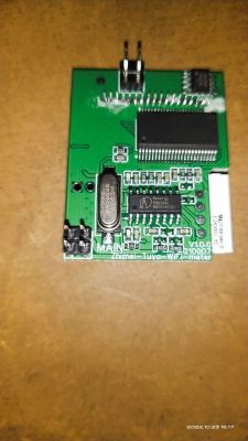
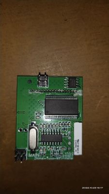
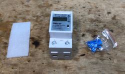
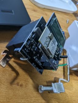
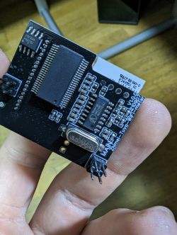
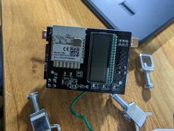
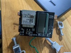
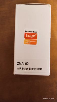
    Attaching a photo of the counter, the CBU module.

    Who can help with GPIO for this counter, I will be very grateful!
    Zmai-90 with CBU module does not start after flashing. Could not pick up GPIO.Zmai-90 with CBU module does not start after flashing. Could not pick up GPIO. Zmai-90 with CBU module does not start after flashing. Could not pick up GPIO.Zmai-90 with CBU module does not start after flashing. Could not pick up GPIO.Zmai-90 with CBU module does not start after flashing. Could not pick up GPIO.Zmai-90 with CBU module does not start after flashing. Could not pick up GPIO.Zmai-90 with CBU module does not start after flashing. Could not pick up GPIO.Zmai-90 with CBU module does not start after flashing. Could not pick up GPIO.
  • ADVERTISEMENT
  • #2 20250592
    p.kaczmarek2
    Moderator Smart Home
    Hello @ghost198922 . Thank you for posting, this is a Zmai-90 version that I haven't seen before. I actually have one, but my one is WB3S-based (BK7231T) and not CBU (BK7231N).
    Zmai-90 with CBU module does not start after flashing. Could not pick up GPIO.
    Zmai-90 with CBU module does not start after flashing. Could not pick up GPIO. Zmai-90 with CBU module does not start after flashing. Could not pick up GPIO.
    Still, there should be no problem with that - OpenBeken already supports BK7231T, BK7231N, XR809, BL602, W800, W600 and T34.
    The only thing that the UART protocol is not yet implemented - but I think I can do it for you. can you wait, hopefully, several days? Maybe week, depends on amount on my free time and family matters.

    As said, I have this device at hand so I can look into it quickly.

    Question: do you have an original firmware backup?
    Helpful post? Buy me a coffee.
  • #4 20256982
    p.kaczmarek2
    Moderator Smart Home
    Isn't your device a TuyaMCU one?
    Can you try following steps from that topic:
    https://www.elektroda.com/rtvforum/topic3928897.html#20256920
    Helpful post? Buy me a coffee.
  • ADVERTISEMENT
  • #5 20262922
    ghost198922
    Level 3  
    p.kaczmarek2 wrote:
    Isn't your device a TuyaMCU one?
    Can you try following steps from that topic:
    https://www.elektroda.com/rtvforum/topic3928897.html#20256920


    Hi tried to create autoexec.bat file in LFS with code like this

    
    startDriver TuyaMCU
    
    setChannelType 1 ReadOnly
    linkTuyaMCUOutputToChannel 1 2 1
    
    setChannelType 2 ReadOnly
    linkTuyaMCUOutputToChannel 6 0 2
    
    setChannelType 3 ReadOnly
    linkTuyaMCUOutputToChannel 9 5 3
    
    setChannelType 4 Toggle
    linkTuyaMCUOutputToChannel 16 1 4
    setChannelType 5 ReadOnly
    linkTuyaMCUOutputToChannel 17 0 5
    setChannelType 6 ReadOnly
    linkTuyaMCUOutputToChannel 18 0 6
    
    setChannelType 10 ReadOnly
    linkTuyaMCUOutputToChannel 101 2 10
    setChannelType 11 ReadOnly
    linkTuyaMCUOutputToChannel 102 2 11
    setChannelType 12 ReadOnly
    linkTuyaMCUOutputToChannel 103 2 12
    setChannelType 13 ReadOnly
    linkTuyaMCUOutputToChannel 105 2 13
    setChannelType 14 ReadOnly
    linkTuyaMCUOutputToChannel 109 2 14
    setChannelType 15 ReadOnly
    linkTuyaMCUOutputToChannel 110 2 15
    setChannelType 16 ReadOnly
    linkTuyaMCUOutputToChannel 111 2 16


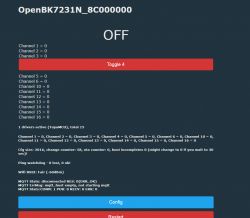
    The button does not respond, there is no data on the LCD counter.
    Zmai-90 with CBU module does not start after flashing. Could not pick up GPIO.

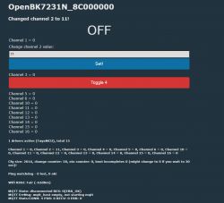
    Then I tried to enter commands, and send a number, the answer is below. The relay does not respond.
    setChannelType 2 TextField
    linkTuyaMCUOutputToChannel 9 4 2

    Zmai-90 with CBU module does not start after flashing. Could not pick up GPIO.

    There is no data with the TuyaMCU flag in the logs.
  • #7 20275820
    p.kaczmarek2
    Moderator Smart Home
    Have you tried just sniffing the UART commands of original firmware? First on the TX of MCU and then on the RX?
    Helpful post? Buy me a coffee.
  • ADVERTISEMENT
  • #8 20282149
    ghost198922
    Level 3  
    p.kaczmarek2 wrote:
    Have you tried just sniffing the UART commands of original firmware? First on the TX of MCU and then on the RX?


    Hello. I'm new in this business. Give instructions on how to do it right. You can link to the manual.
  • #9 20282235
    p.kaczmarek2
    Moderator Smart Home
    Maybe let's do this slightly other way, just to be sure.

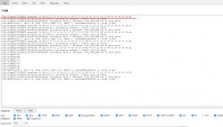
    In OpenBeken, when you go to Web Panel, and open Log, do you get messages like that:
    Zmai-90 with CBU module does not start after flashing. Could not pick up GPIO.

    Like that:
    
    Info:TuyaMCU:TUYAMCU received: 55 AA 03 07 00 13 06 00 00 0F 00 00 00 BF 00 00 01 3C 01 F8 00 06 4F 09 30 B4 
    

    is OpenBeken receiving any TuyaMCU packets?
    Helpful post? Buy me a coffee.
  • #10 20283620
    ghost198922
    Level 3  
    p.kaczmarek2 wrote:
    Maybe let's do this slightly other way, just to be sure.

    In OpenBeken, when you go to Web Panel, and open Log, do you get messages like that:
    Zmai-90 with CBU module does not start after flashing. Could not pick up GPIO.

    Like that:
    
    Info:TuyaMCU:TUYAMCU received: 55 AA 03 07 00 13 06 00 00 0F 00 00 00 BF 00 00 01 3C 01 F8 00 06 4F 09 30 B4 
    

    is OpenBeken receiving any TuyaMCU packets?


    There are no packets from TuyaMCU in OpenBeken in Web Panel, the TuyaMCU driver itself is running.
  • #11 20449906
    javierlt3
    Level 4  
    Hi it is the device working well now? Does it work with Home assistant?
  • ADVERTISEMENT
  • #12 20449967
    p.kaczmarek2
    Moderator Smart Home
    Hello @javierlt3 , do you have the same device model?
    Helpful post? Buy me a coffee.
  • #13 20450258
    javierlt3
    Level 4  
    Yes, with the same chip the cbu Zmai-90 with CBU module does not start after flashing. Could not pick up GPIO. Zmai-90 with CBU module does not start after flashing. Could not pick up GPIO. Zmai-90 with CBU module does not start after flashing. Could not pick up GPIO. Zmai-90 with CBU module does not start after flashing. Could not pick up GPIO.
  • #14 20451809
    javierlt3
    Level 4  
    @p.kaczmarek2 I don't know if the new firmware it's going to work if I flash it because I have no more info about if they decode the log and all the things, I just want to add it to home assistant
    ty in advance
  • #15 20451950
    p.kaczmarek2
    Moderator Smart Home
    @javierlt3 maybe you can start with doing TuyaMCU packets capture. Do not change the firmware yet, just power the device somehow by analyzing the PCB and checking where is the 5V rail, then artificially power the 5V rail, do not power it from mains, and connect USB to UART RX to first RX and then TX lines and capture TuyaMCU packets in binary format for further analysis. Of course USB to UART ground also should be connected.

    Realterm has a very nice "capture to file" option.

    Once you do full TuyaMCU packets capture, then adding support will be very easy.
    Helpful post? Buy me a coffee.
  • #16 20551335
    Jinaria
    Level 8  
    I have some of the same DIN rail meter, with the same components, I managed to find some pins but faced a strange issue with the relay.
    Here are pins that I found so far:

    Wifi Led: Pin 6
    Button : Pin 7
    Relay: Pin 14
    Pins 15 and 17 connected to 24C02H EEPROM SCL/SDA (pin 5 and 6)
    Tripped OFF Led: Pin 26
    TX1 : Connected to Pin 13 of Renergy RN8209C Measuring chip (RX)
    RX1 : Connected to Pin 12 of Renergy RN8209C Measuring chip (TX)

    When I configured the relay pin, the first time I heard a relay click, after that there was no click at all and it just made a static noise when I turned the relay on! flashed the second one and the exact same thing happened.
    I am not sure how to get measurement data from RN8209C or how to save the measurement data to EEPROM, also the lcd controller chip has no marking, not sure how to control LCD as well.

    Added after 1 [hours] 47 [minutes]:

    tried loading TuyaMCU but there's nothing about it in the log.
    @p.kaczmarek2 is it possible to display the data being sent to RX1?

    Here is a datasheet for RN8209C : https://datasheet.lcsc.com/lcsc/2304111530_RENERGY-RN8209C_C80223.pdf
    Also this one seems to be the SDK: https://github.com/RN8209C/RN8209C-SDK
    Arduino Library for 24C02 EEPROM : https://github.com/jlesech/Eeprom24C01_02/tree/master
  • #17 20551589
    p.kaczmarek2
    Moderator Smart Home
    @Jinaria , have you checked both possible baud rates? Have you started tuyaMCU driver?

    Configs (autoexec.bat) to try:
    
    startDriver TuyaMCU
    // force 'paired' state for TuyaMCU
    tuyaMcu_defWiFiState 4
    

    second option:
    
    startDriver TuyaMCU
    tuyaMcu_setBaudRate 115200
    // force 'paired' state for TuyaMCU
    tuyaMcu_defWiFiState 4


    PS: There is also an analyzer tool for use before flashing OBK:
    https://www.elektroda.com/rtvforum/topic3970199.html#20528459
    Helpful post? Buy me a coffee.
  • #18 20551799
    Jinaria
    Level 8  
    Yes. Already tried that, but received nothing from the tuyamcu, In the log I have:

    ExtraDebug:TuyaMCU:TuyaMCU heartbeat_valid = 0, product_information_valid=0, self_processing_mode = 1, wifi_state_valid = 0, wifi_state_timer=0

    Then I noticed in the datasheet that the max baudrate for the rn8209c is fixed at 4800, so tried :
    startDriver TuyaMCU
    tuyaMcu_setBaudRate 4800
    tuyaMcu_defWiFiState 4

    but still nothing.
  • #20 20551902
    Jinaria
    Level 8  
    That's for RN8209D, The chip on my device is RN8209C and it is fixed at 4800 :

    Zmai-90 with CBU module does not start after flashing. Could not pick up GPIO.
  • #21 20551929
    p.kaczmarek2
    Moderator Smart Home
    An UART capture from unflashed device (original tuya software) would help a lot.

    You can restore backup with latest bk7231 gui flash tool:
    https://github.com/openshwprojects/BK7231GUIFlashTool
    Helpful post? Buy me a coffee.
  • #22 20551942
    Jinaria
    Level 8  
    I have one unflashed device, I'll try to capture. First I have to figure out how to do it safely without using mains and injecting 3.3v to the correct pins. Do I have to capture RX and TX separately?
  • #23 20551958
    p.kaczmarek2
    Moderator Smart Home
    First thing to try would be to search for AMS1117-3.3V LDO on the board and try to inject 5V USB power supply on it input. Maybe it would work. I am not sure. Working with mains is very dangerous.

    We don't even know if it's a TuyaMCU device, but for TuyaMCU there is a tool:
    https://www.elektroda.com/rtvforum/topic3970199.html

    Unfortunatelly, you have to capture both from RX and TX. One line is what WiFi module sends to MCU, and second is what WiFi module receives from MCU.
    Helpful post? Buy me a coffee.
  • #24 20552966
    Jinaria
    Level 8  
    I captured RX and TX @ 4800, analyzer software does not show anything.

    TX capture from RN8209C :
    000208D3FFFFFFFFDD0000CD0E00020BD0FFFFFFFFDD0000BA21000202D9FFFFFFFFDD0000BC1F00020ECDFFFFFFFFDD0000B724000208D3FFFFFFFFDD0000C01B000207D4FFFFFFFFDD0000BC1F000209D2FFFFFFFFDD0000B82300020AD1FFFFFFFFDD0000B922000212C9FFFFFFFFDD0000C417000209D2FFFFFFFFDD0000BB20000209D2FFFFFFFFDD0000B724000204D7FFFFFFFFDD0000B62500020BD0FFFFFFFFDD0000B82300020FCCFFFFFFFFDD0000C21900020AD1FFFFFFFFDD0000B823000207D4FFFFFFFFDD0000C11A0001F8E4FFFFFFFFDD0000C21900020CCFFFFFFFFFDD0000B62500020AD1FFFFFFFFDD0000C11A00020BD0FFFFFFFFDD0000B823000207D4FFFFFFFFDD0000BD1E00020CCFFFFFFFFFDD0000CA11000212C9FFFFFFFFDD0000C219000209D2FFFFFFFFDD0000C11A00020DCEFFFFFFFFDD0000BF1C000208D3FFFFFFFFDD0000B625000209D2FFFFFFFFDD0000BA21000204D7FFFFFFFFDD0000BD1E00020AD1FFFFFFFFDD0000B92200020AD1FFFFFFFFDD0000BC1F000210CBFFFFFFFFDD0000CC0F000203D8FFFFFFFFDD0000B625000206D5FFFFFFFFDD0000B82300020ECDFFFFFFFFDD

    RX capture from RN8209C :
    242226242226242226242226242226242226242226242226242226242226242226242226242226242226242226242226242226242226242226242226242226242226242226242226242226242226242226242226242226242226242226242226242226242226242226242226242226242226242226242226242226242226242226242226242226242226242226242226242226242226242226242226242226242226242226242226242226242226242226242226242226242226242226242226242226242226242226242226242226242226242226242226242226242226242226242226242226242226242226242226242226242226242226242226242226242226242226242226242226242226242226
  • #25 20553116
    p.kaczmarek2
    Moderator Smart Home
    I remember seeing that article about ZMAI 90 with a custom protocol:
    https://www.creationfactory.co/2019/12/reverse-engineering-zmai-90-din-rail.html
    but it's for V9261F:
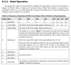
    Zmai-90 with CBU module does not start after flashing. Could not pick up GPIO.
    I don't think it's the same.

    It seems we will have to write a custom driver for that. Please disconnect UART capture, I will prepare an empty driver stub for you, then I will need you to connect it to mains and do some UART captures because we need to know which value is which. I will need you to:
    - connect 60W bulb, copy captures from OpenBeken panel (I will add a driver stub for that)
    - connect 20W bulb, do copy from OBK again....
    etc etc so we can guess which value is which.

    Do you still have that one device with OpenBeken flashed? Is it connected to mains?
    Helpful post? Buy me a coffee.
  • #26 20553182
    Jinaria
    Level 8  
    That would be great.

    Yes I have both devices in hand, since this device has LCD, for unflashed device, I can also see the value reported by the chip. Do I have to activate the the device with factory flash on Tuya app?
  • #27 20554248
    Jinaria
    Level 8  
    I did some tests and here are my new findings:

    - The relay is Bistable relay connected to pins P14 and P16, so to open/close the relay we should use Bridge driver:
     "pins": {
        "6": "WifiLED;1",
        "7": "Btn;0",
        "14": "BridgeREV;0",
        "16": "BridgeFWD;0",
        "26": "LED_n;0"
      },

    The pulse length should be set to 5 using "BridgePulseLength 5" but at the moment it is not allowed to be set to any value lower than 50.

    - The LCD controller is connected to pins P9 and P28 but the controller has no marking.
    - The impulse Led connection seems to be controlled by the metering chip.
  • #28 20554415
    p.kaczmarek2
    Moderator Smart Home
    Thank you, I saw that pull request, it should be merged now. I didn't know it was yours, I support to many devices at one time to realize.
    Jinaria wrote:
    I can also see the value reported by the chip. Do I have to activate the the device with factory flash on Tuya app?

    Sorry, what do you mean by activate the device with factory flash? You mean pair?

    Well, it depends, is device fully functional without pairing?

    Hmm I think we could benefit from pairing it with Tuya because then we will know what can be reported by MCU, which values can we find in the packets.
    Helpful post? Buy me a coffee.
  • #29 20554534
    Jinaria
    Level 8  
    Thanks,
    - "BridgePulseLength 5" has fixed the relay issue for me.
    - Yes, I meant pairing. Without pairing with the tuya app, the lcd is functional and it does show some information about voltage, current, ... but the button does not do anything which is not important since I know how to drive the relay now.
    - Next I am interested in checking the EEPROM content, it's connected to Pins 15 and 17. I have a CH341 Pro but I'm not sure if it's compatible with the chip.
    - Also interested to find out how to drive the LCD but as the LCD controller doesn't have any marking, it's going to be hard.
  • #30 20554660
    p.kaczmarek2
    Moderator Smart Home
    We have CH341 tutorial:
    https://www.youtube.com/watch?v=z9uLPo9QAY8
    Regarding UART testing, I will try to give you details what to do today or tomorrow.

    Added after 1 [hours] 41 [minutes]:

    @Jinaria please do this steps:
    1. update obk
    2. in console:
    uartInit 4800

    3. then to send something in hex, for example try:
    uartSendHex 2226242226

    and see if you are getting any replies

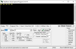
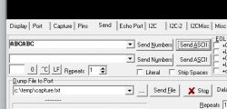
    Here is my test setup with Realtem:
    Zmai-90 with CBU module does not start after flashing. Could not pick up GPIO.
    Zmai-90 with CBU module does not start after flashing. Could not pick up GPIO.
    as you can see, the realterm receives bytes:
    Zmai-90 with CBU module does not start after flashing. Could not pick up GPIO.
    of course, when i send something from realterm, i can receive it again on obk:
    Zmai-90 with CBU module does not start after flashing. Could not pick up GPIO.
    Zmai-90 with CBU module does not start after flashing. Could not pick up GPIO.

    My question now is - is the uart test system working for you and are you able to receive something back from the MCU by sending a bytes combination similar to 2226242226 on UART?
    Helpful post? Buy me a coffee.

Topic summary

The discussion revolves around issues faced with the Zmai-90 device equipped with a CBU module after flashing it with OpenBK firmware. Users report that the device fails to start, with no data displayed on the LCD and GPIO pins not being recognized. Various troubleshooting steps are suggested, including creating an autoexec.bat file for TuyaMCU commands, capturing UART communications, and checking the device's pin connections. Some users have successfully flashed the device and are working on calibrating the RN8209 driver for accurate readings. The conversation highlights the need for a custom driver due to the unique communication protocol of the Zmai-90 and the challenges in restoring original firmware.
Summary generated by the language model.
ADVERTISEMENT