logo elektroda
logo elektroda
X
logo elektroda

Tuya Single Phase Energy Meter 6 In 1: CBU Chip Flashing & ESPHome Integration Issues

deanfourie 11682 96
ADVERTISEMENT
  • #31 20350986
    deanfourie
    Level 6  
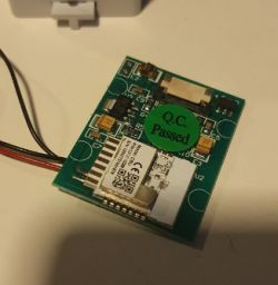
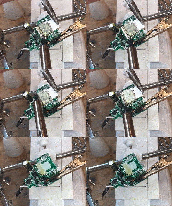
    Ok here is what I have.
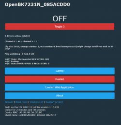
    Tuya Single Phase Energy Meter 6 In 1: CBU Chip Flashing & ESPHome Integration Issues Tuya Single Phase Energy Meter 6 In 1: CBU Chip Flashing & ESPHome Integration Issues

    Added after 46 [minutes]:

    Also, tried to connect to wifi but it has not connected.

    Put the correct details in, but cannot see any active lease for it. Checked the DHCP server, nothing.

    Also tried to reach it at the static of 192.168.4.1, nothing. Tried 2 different APs too.

    Any ideas?

    Added after 1 [hour] 41 [minutes]:

    Ok ok wait its working fine, it is only 2.4 haha.

    Have joined to my wifi and able to browse to the device and hit the webpage.

    Now trying to configure with MQTT.

    Is this going to be ESPHome compatible at all?

    Thanks

    Added after 4 [hours] 31 [minutes]:

    Ok here's an update.

    I have connected the device to wifi and have also connected it to homeassistant via MQTT.

    The only issue is it only has one entity showing, which is a switch.

    There is no entity displaying the current output.
  • ADVERTISEMENT
  • #32 20351359
    p.kaczmarek2
    Moderator Smart Home
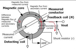
    Does the 813 channel0 value changes with the current? We don't have a driver for ADC-based current sensor yet, would you be able to help with testing new one? I must check how other firmwares handle that. Still, it looks relatively simple. We could write one (or port) for you. Most like it will need a user calibration, just like in Tasmota, with an external meter:
    Tuya Single Phase Energy Meter 6 In 1: CBU Chip Flashing & ESPHome Integration Issues

    Really, we have above 150 user device teardowns on our list and you are the first person with non-contact current measuring device. It was always BL0937/BL0942/CSE/TuyaMCU so far. https://openbekeniot.github.io/webapp/devicesList.html

    Sorry, Beken chips are 2.4GHz only. It's not our fault, they just support only that standard.

    Regarding compatibility - we are trying to provide support for all common ESPhome/tasmota features, you can pair with HA, run sensors, script devices, and we also support the popular command syntaxes, Tasmota JSON requests (partially, still improving), Tasmota DGR protocol....

    Good job with pairing with HA! I will guide you also with measurements result reading later, once the measuring driver is ready.

    Ok, now, does that ADC reading changes with the current? Are we sure that this ADC port is used here?
    Helpful post? Buy me a coffee.
  • #33 20351368
    deanfourie
    Level 6  
    Great I will help with testing.

    I will install one tomorrow and let you know what the readings are.

    Will report back
  • #34 20352330
    deanfourie
    Level 6  
    Hi, is there a way in your firmware to set a static IP?

    Also, when added in HA via MQTT, I am only seeing a "Switch" under the entity. Nothing more.

    Thanks

    Added after 35 [minutes]:

    Also, I can confirm the value is changing when power is passing through.
  • #35 20352389
    p.kaczmarek2
    Moderator Smart Home
    Hello @deanfourie ,
    The HA autodiscovery is implemented for basic types of devices, so you will most likely have to use YAML method - write your own entry of configuration.yaml.

    The static IP is usually done by DHCP MAC reserveration on your router, but if you need it on the OBK, we can consider implementing it for you.

    Now regarding the driver - we will need to figure out how to process this ADC value in the software. Can you tell me what kind of readings original Tuya software from this meter provides?
    Helpful post? Buy me a coffee.
  • #36 20352402
    deanfourie
    Level 6  
    p.kaczmarek2 wrote:
    The static IP is usually done by DHCP MAC reservation on your router, but if you need it on the OBK, we can consider implementing it for you.


    I think this would be a great addition to the web config, as I like to keep all my devices static as I have a very small address space and prefer to leave DHCP for initial setup of devices where possible.

    p.kaczmarek2 wrote:
    Now regarding the driver - we will need to figure out how to process this ADC value in the software. Can you tell me what kind of readings original Tuya software from this meter provides?


    I have no idea. I never used these with the default Tuya app. I just straight away wanted to get them off the Tuya platform. But I am seeing the Value change which I'm guessing is a good sign. We have the correct pin for monitoring the current?

    Also, is it possible to flash the devices now over the web and not via serial for future updates?

    Added after 4 [minutes]:

    Also, one more issue.

    There seems to somehow have been a duplicate, I noticed one device was getting the same IP as the other and after checking the MAC, I noticed that it had the same MAC as the other device.
    Upon checking the config, I found that there are also duplicates in the names and topics and unique IDs etc and as a result it only shows 2 out of the 3 in HA.

    mqtt:
      switch:
      - unique_id: "OpenBK7231N_085ACDD0_relay_3"
        name: "obk085ACDD0 3"
        state_topic: "obk085ACDD0/3/get"
        command_topic: "obk085ACDD0/3/set"
        qos: 1
        payload_on: 1
        payload_off: 0
        retain: true
        availability:
          - topic: "obk085ACDD0/connected"
          
      switch:
      - unique_id: "OpenBK7231N_085ACDD0_relay_3"
        name: "obk085ABDD0 3"
        state_topic: "obk085ABDD0/3/get"
        command_topic: "obk085ABDD0/3/set"
        qos: 1
        payload_on: 1
        payload_off: 0
        retain: true
        availability:
          - topic: "obk085ABDD0/connected"
          
      switch:
      - unique_id: "OpenBK7231N_085ABAC8_relay_3"
        name: "obk085ABAC8 3"
        state_topic: "obk085ABAC8/3/get"
        command_topic: "obk085ABAC8/3/set"
        qos: 1
        payload_on: 1
        payload_off: 0
        retain: true
        availability:
          - topic: "obk085ABAC8/connected"
  • #37 20354694
    p.kaczmarek2
    Moderator Smart Home
    Can you please pair one of your devices with Tuya app and show what is measured by it? I am confused, because if there is a current transformer then it should just measure current, and not the voltage, right? But maybe some other IO is used somehow else... no idea yet. Hard to tell, I don't have this device in front of me.

    Quote:

    after checking the MAC, I noticed that it had the same MAC as the other device.

    No problem, we have tool for that - you can change MAC in Config, and if your BK RF partition is lost, then you can in Web Application restore it.
    Helpful post? Buy me a coffee.
  • #38 20355047
    deanfourie
    Level 6  
    Thanks,

    I may measure voltage, as this is how the unit is powered, via 240v AC.

    I'm ok with just getting the Current readouts though.

    As for connecting to Tuya, this might be an issue as all devices are flashed :roll:

    Added after 29 [minutes]:

    Is there a way to send the data that is received when the current changes as a Topic via MQTT?

    That would at least give the current readout. Right now it's only giving a switch as an entity.
  • #39 20355143
    p.kaczmarek2
    Moderator Smart Home
    I am asking about voltage because we also need to get that device supported for other users in the future so it's good to have full profile.

    Our OpenBeken is fully scriptable, you can publish and receive whatever you want. If you have set ADC pin to channel, for example, 2, then you will get "obkName/2/get" publishes with the ADC result value and you can listen to them in HA.

    You can also multiply it in HA. For example, here is my TH06 sensor YAML:
    Code: YAML
    Log in, to see the code

    As you can see, the YAML below is a demonstration of post-scaling channel value in HA. In case of temperature it is multiplied by 0.1.
    If the ADC value just requires a multiplication or division to get current reading, you can just do a test with 60W bulb and figure out the constant and do the scaling on HA side and you'll get current.

    You can of course also add "change handlers" to channels and postprocess values there, but I think that at the end, for you I will just add a hardcoded driver. This will be easier for further users.

    But let's start with basics. How much ADC is showing for 10W load, and how much for 60W load?
    Helpful post? Buy me a coffee.
  • ADVERTISEMENT
  • #40 20355440
    deanfourie
    Level 6  
    Ok, slight problem. Tried doing the test you asked for but the value does not seem to change.

    I thought it was fine as I tested it before, but it's really not changing, it kind of just fluctuates between 810 and 840.

    Any ideas?
  • #41 20355639
    p.kaczmarek2
    Moderator Smart Home
    We need more information. We need to reverse engineer this device. I did such things in the past, for example for QTouch no-neutral switch in this topic (sorry, Polish language!):
    https://www.elektroda.pl/rtvforum/topic3793509.html
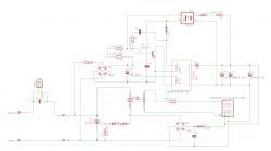
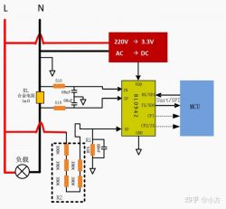
    I drawn this schematic:
    Tuya Single Phase Energy Meter 6 In 1: CBU Chip Flashing & ESPHome Integration Issues
    You don't need to draw whole schematic, but we really need to know this device does (check in Tuya App?) and what are pin roles, where which signal from CBU goes.

    I can write a driver specifically for you, per your request, but I don't know what's going on that PCB. It would be really helpful to sketch the connections, where are the resistor connected, where the measurement coil (I+ and I- goes), etc.

    The second option is to find the Tasmota template for this device, and if it matches, we can use knowledge from there.

    I will also double-check ADC handling for N and T.
    Helpful post? Buy me a coffee.
  • #43 20356800
    p.kaczmarek2
    Moderator Smart Home
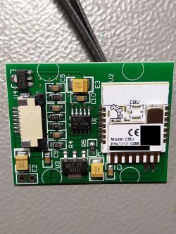
    That moment when I see it...
    Can you tell me what is under that green sticker here?
    Tuya Single Phase Energy Meter 6 In 1: CBU Chip Flashing & ESPHome Integration Issues
    because, according to the link you posted, there is a already-mentioned BL0942 underneath...
    Home assistant forum wrote:

    Tuya Single Phase Energy Meter 6 In 1: CBU Chip Flashing & ESPHome Integration Issues
    Helpful post? Buy me a coffee.
  • #44 20356813
    deanfourie
    Level 6  
    Is it possible to flash one back to stock Tuya for testing?
  • #45 20356830
    p.kaczmarek2
    Moderator Smart Home
    If I am correct, then it's not needed.

    But yes, you can reflash, if you have a backup.

    Just do "startDriver BL0942" in short startup command and reboot. BL0942 in UART mode is supported.

    You can also check to confirm, are BL0942 RX and TX pins connected to RXD1 and TXD1 of WiFi module?
    Tuya Single Phase Energy Meter 6 In 1: CBU Chip Flashing & ESPHome Integration Issues
    Helpful post? Buy me a coffee.
  • #46 20356873
    deanfourie
    Level 6  
    By WiFi module, you mean the BKN CBU right?

    Added after 9 [minutes]:

    Damn! That is a BL0942 chip! Not sure how I missed that.
  • #47 20356885
    p.kaczmarek2
    Moderator Smart Home
    This explains a lot of things.

    Now, we need to check is that BL0942 connected in UART mode?

    Does BL0942 RX and TX connects to BKN CBU TXD1 RXD1?

    Second option: enter "startDriver BL0942" in short startup command, reboot and see what you get. Also check logs.

    How good are your soldering skills?
    Helpful post? Buy me a coffee.
  • #48 20356891
    deanfourie
    Level 6  
    Which pins on BL0942 are TX/RX?

    Soldering skills are pretty good, I'm pretty comfortable with my TS100.
  • ADVERTISEMENT
  • #49 20356896
    p.kaczmarek2
    Moderator Smart Home
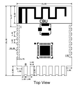
    Here is the CBU documentation:
    https://developer.tuya.com/en/docs/iot/cbu-module-datasheet?id=Ka07pykl5dk4u
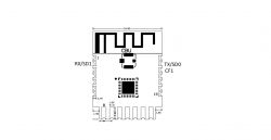
    Tuya Single Phase Energy Meter 6 In 1: CBU Chip Flashing & ESPHome Integration Issues
    15TX1I/OUART_TX1, which is used for transmitting user data and corresponds to Pin 27 of the IC. For the MCU solution, please refer to CBx Module.
    16RX1I/OUART_RX1, which is used for receiving user data and corresponds to Pin 26 of the IC. For the MCU solution, please refer to CBx Module.


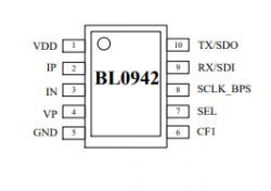
    Here is BL0942:
    Tuya Single Phase Energy Meter 6 In 1: CBU Chip Flashing & ESPHome Integration Issues

    We need to know whether BL0942 is connected in UART or in SPI mode.

    Now, there are two potential scenarios...
    Spoiler:
    Scenario 1: if BL0942 is connected in UART mode, then everything is solved, we have a BL0942 driver, which even works with NTP, gathers stats, etc, (thanks @valeklubomir - our important contributor! He did a lot of work for OBK)
    Scenario 2: if BL0942 is in SPI mode, then there are two next options, because SPI mode is not supported yet and I have never seen it before and we already have above 150 devices in templates list and none of them ever had SPI mode, so... if it's SPI, then you can either wait for me to add SPI mode, or just solder jumper wires and cut traces so BL0942 is switched to UART mode and you get it working within 30 minutes (I know how to solder etc and it's really, just 15 minutes job)
    Helpful post? Buy me a coffee.
  • #50 20356924
    deanfourie
    Level 6  
    Ok, I have no continuity between the BL0942 and the CBU

    TX > RX - No Continuity
    RX - TX - No Continuity

    With that said, I'm testing on the unit that I blew up.

    Pretty solid BANG.

    Not sure if the chips were affected,
  • #51 20356996
    p.kaczmarek2
    Moderator Smart Home
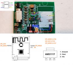
    So where are connected the following pins: TX/SDO , RX/SDI , SCLK_BPS, and CF1?
    Tuya Single Phase Energy Meter 6 In 1: CBU Chip Flashing & ESPHome Integration Issues
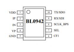
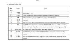
    Here are the pin roles of BL0942:
    Tuya Single Phase Energy Meter 6 In 1: CBU Chip Flashing & ESPHome Integration Issues
    Please check the SEL pin. Is it connected to VDD? SEL connected to VDD means SPI. We want UART.

    If your device is using BL0942 in SPI mode, which is a first time ever I encounter this, then easiest way it to put it back in UART mode. Just do the following steps for next device in order to pair it with HA:
    1. First of all, do finally a flash read first (you did it in the past but you overwrote it later? I am not sure, see read and write commands from the first page of this topic)
    2. Then flash OpenBeken (write operation)
    3. Then you have to cut the trace - disconnect SEL from VDD, in order to turn BL0942 into UART mode
    4. Then cut traces at BL0942 TX/RX/SCLK pins
    5. Then connect BL0942 RX to CBU TX and BL0942 TX to CBU RX
    6. Also make sure that SCLK/BPS pin of BL0942 is connected to ground to select baud 4800:
    Tuya Single Phase Energy Meter 6 In 1: CBU Chip Flashing & ESPHome Integration Issues
    7. Then add "startDriver BL0942" to short startup command and reboot
    8. Then you should be able to do the Calibration in our firmware: connect 60W bulb, measure current and voltage, and use commands: VoltageSet [VoltageFromReliableMeter], CurrentSet [CurrentFromReliableMeter], PowerSet [PowerFromReliableMeter]
    This should get your device running and measuring voltage, current and power

    I know it might sound as much, but really, it's a quick job, you just need some flux, clean soldering iron tip, and Pb solder and everything is easy.
    Helpful post? Buy me a coffee.
  • #52 20357223
    deanfourie
    Level 6  
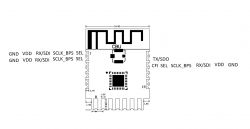
    This is the pinout I get using continuity to test.

    Tuya Single Phase Energy Meter 6 In 1: CBU Chip Flashing & ESPHome Integration Issues

    Added after 3 [minutes]:

    Honestly, I'm more worried about cutting the traces than soldering.
  • #53 20357243
    p.kaczmarek2
    Moderator Smart Home
    Sorry, I am not sure if I understand the notation - are you saying that VDD and GND and RX/SDI and SCLK_BPS connects to the same pin?
    Tuya Single Phase Energy Meter 6 In 1: CBU Chip Flashing & ESPHome Integration Issues

    If you don't want to cut the traces, then we are able to use a bit more clever approach.
    For example, from what I am seeing, the SCLK_BPS should be at level 0 for 4800 baud.
    If SCLK_BPS track is connected to, let's say, for example, P9 signal (not pin 9 of CBU, but P9), then you can in our software set P9 role to "AlwaysLow". This will do the same as shorting that signal to ground, but it in a more easy way.
    Helpful post? Buy me a coffee.
  • #54 20357252
    deanfourie
    Level 6  
    Yes, they literally all ring out to the same pin?
  • #55 20357273
    p.kaczmarek2
    Moderator Smart Home
    It is impossible. You can't get 0 ohm continuity result between VDD and GND. You must be testing on a broken device, as you mentioned?

    If this is the fried device, please now desolder CBU and BL0942 and check again, but just follow the traces, because burnt circuits are biasing your results. Do a high quality photo of the traces and remember where BL0942 first pin was.

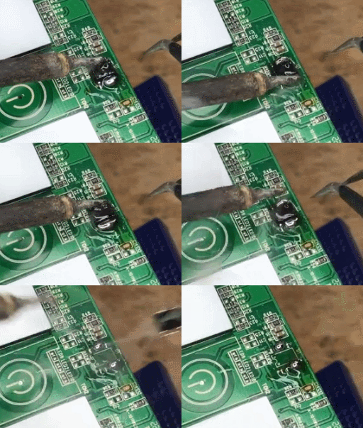
    BL0942 can be removed with the technique from this video (I link to a specific timestamp):
    Close-up of a circuit board with a component being desoldered using a soldering tool.
    https://youtu.be/Yb3zXtBdSnE?t=156

    The CBU can be removed with method from here (sorry, this particular guide is in polish only, but has english subtitles):
    Printed circuit board with electronic components clamped with clips.
    https://youtu.be/7MyfSgxLAOo?t=121
    It has more pins but should be doable. I already desoldered WB3S that way as well.

    I am assuming that you are testing on broken device, then you can just desolder those parts to get knowledge.

    Second option would be to check on a device that was not broken
    Helpful post? Buy me a coffee.
  • #56 20357313
    deanfourie
    Level 6  
    Ok here's what I came up with.

    I cannot however find SCLK_BPS.

    Tuya Single Phase Energy Meter 6 In 1: CBU Chip Flashing & ESPHome Integration Issues

    Added after 2 [minutes]:

    Struggled to get the CBU up, lifted a few pads but still have access to the traces
  • ADVERTISEMENT
  • #57 20357353
    p.kaczmarek2
    Moderator Smart Home
    Very good job. We are progressing quickly. This meter will be up and running with all measurements soon.

    Can you post some detailed photos?

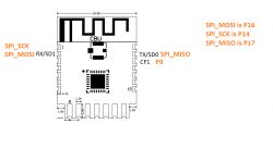
    Isn't SCLK_BPS connected to the SPI_SCK? See your modified picture:
    Tuya Single Phase Energy Meter 6 In 1: CBU Chip Flashing & ESPHome Integration Issues
    Here is a list of SPI pins on CBU:
    Pin numberSymbolI/O typeFunction
    1P14I/OCommon GPIO, which can be reused as SPI_SCK (Correspond to Pin 11 of the IC)
    2P16I/OCommon GPIO, which can be reused as SPI_MOSI (Correspond to Pin 12 of the IC)
    20P17I/OCommon GPIO, which can be reused as SPI_MISO (Correspond to Pin 14 of the IC)
    21P15I/OCommon GPIO, which can be reused as SPI_CS (Correspond to Pin 13 of the IC)


    It confirms it's SPI. We will need to think carefully how to reroute it to UART easily. We can reduce the amount of trace-cutting with some trickery. We have "AlwaysLow" and "AlwaysHigh" pin states in our software.

    PS: It's "SDI", as in "serial data input", and "SDO", as in "serial data output". Not "SD1" and not "SD0".
    Tuya Single Phase Energy Meter 6 In 1: CBU Chip Flashing & ESPHome Integration Issues
    Helpful post? Buy me a coffee.
  • #58 20357429
    deanfourie
    Level 6  
    To be honest it's a bit of a mess. My apologies.

    But, honestly there doesn't look like there was even a trace on PIN 1 of the CBU.

    Tuya Single Phase Energy Meter 6 In 1: CBU Chip Flashing & ESPHome Integration Issues

    p.kaczmarek2 wrote:
    PS: It's "SDI", as in "serial data input", and "SDO", as in "serial data output". Not "SD1" and not "SD0".

    Ok good to know! Still learning.
  • #59 20357491
    p.kaczmarek2
    Moderator Smart Home
    Thank you for the photo. Judging from it, SCLK indeed is connected where it should be. You can see there was a trace, if you look closely.
    Tuya Single Phase Energy Meter 6 In 1: CBU Chip Flashing & ESPHome Integration Issues
    Please zoom in photo to see the traces I highlighted in Gimp.
    Where is SEL connected? It goes to via under the board so I am unable to determine that one myself.

    SCLK_BPS is connected to pin 1 of CBU, so you don't have to cut that trace, you can just control P14 in OpenBeken software, set AlwaysLow or AlwaysHigh pin role.

    Now I need to know where SEL is connected. Maybe you can post a good quality photo of second side of the board and I will trace myself, or just try yourself with multimeter
    Helpful post? Buy me a coffee.
  • #60 20357554
    deanfourie
    Level 6  
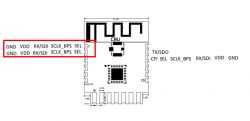
    Ok, from what I can tell doing a continuity test, SEL is connected to the following pins with RED dots.

    Tuya Single Phase Energy Meter 6 In 1: CBU Chip Flashing & ESPHome Integration Issues


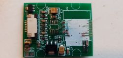
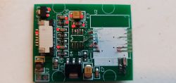
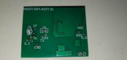
    Here's a shot of the bottom of the board.

    Tuya Single Phase Energy Meter 6 In 1: CBU Chip Flashing & ESPHome Integration Issues

    Thanks

Topic summary

The discussion revolves around issues related to flashing the Tuya Single Phase Energy Meter 6 In 1, which utilizes a CBU chip based on the BK7231N. The user experienced difficulties in flashing the device to integrate it with ESPHome, leading to inquiries about the correct flashing procedure, tools, and binary files. Various responses provided troubleshooting steps, including the use of specific Python tools (hid_download_py, uartprogram) for firmware backup and flashing. The conversation evolved to identify the internal components, particularly the BL0942 chip, and the need to switch from SPI to UART mode for proper communication. The community also discussed calibration and MQTT setup for Home Assistant integration, emphasizing the importance of accurate readings and device configuration.
Summary generated by the language model.
ADVERTISEMENT