logo elektroda
logo elektroda
X
logo elektroda

Tuya Single Phase Energy Meter 6 In 1: CBU Chip Flashing & ESPHome Integration Issues

deanfourie 12252 96
ADVERTISEMENT
  • #61 20357601
    p.kaczmarek2
    Moderator Smart Home
    You have marked both sides of E3, which is impossible under normal circumanstances. You must still have a short on that board.

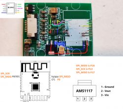
    Still, judging from the documentation, SEL should be on VDD on your device:
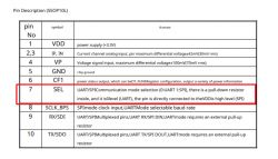
    Tuya Single Phase Energy Meter 6 In 1: CBU Chip Flashing & ESPHome Integration Issues
    While doing the modification, you will have to disconnect SEL from any signals (cut the trace), because there is a pull-down resistor
    inside, and it is0level (UART)


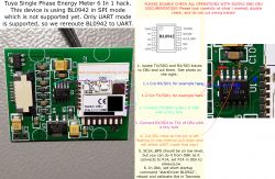
    Ok, I think we have enough information to know what you exactly have to do in order to put next device in UART mode:
    1. disconnect SEL trace (cut the trace before it connects to anything else, so SEL is 'in the air', but the internal pull down resistor sets it to 0 - UART mode)
    2. disconnect TX of BL0942 from old trace (cut it) and connect it to RX1 of CBU
    3. disconnect RX of BL0942 from old trace (cut it) and connect it to TX1 of CBU
    4. Don't do anything about SCLK_BPS, this is for baud rate selection and it connects to P14. You can set P14 to "AlwaysLow" in our software to put logic 0 and SCLK_BPS and choose 4800 bps
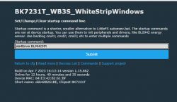
    5. Then, go to Options->Short startup command, enter "startDriver BL0942" and reboot. You should get some readings.

    It is hard to say more without having direct access to the device, but these steps might be enough to get it working. You don't need any firmware changes from our side.

    Please consult attached BL0942 datasheet (english):
    Helpful post? Buy me a coffee.
  • ADVERTISEMENT
  • #62 20358615
    deanfourie
    Level 6  
    Do you reckon you could just list on an image what needs to be cut and joined and I can do it.

    Thanks
  • #63 20358655
    p.kaczmarek2
    Moderator Smart Home
    I could try, but it would be useful if you double-checked if all my steps are correct (compare my guide with datasheet), because you know, it's hard do to that kind of thing entirely remotely.

    At least we have a HD photo of the board, this could prove useful.
    Helpful post? Buy me a coffee.
  • #64 20359091
    deanfourie
    Level 6  
    I can't do this as I don't know what I'm looking for to be honest.

    What else do you need from me to be able to tell me what to do then I can do it.
  • ADVERTISEMENT
  • #65 20360790
    deanfourie
    Level 6  
    Please dont give up on me, we are so close :D
  • #66 20360860
    p.kaczmarek2
    Moderator Smart Home
    I will try, but the problem is it's hard to do full guidance remotely. When I have board in front of myself, I can do all the probing very quickly, it's really a 15 minutes business. But remotely.... well, it's hard.

    I have also one more question, before we start the operation.
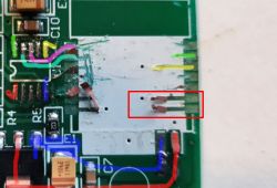
    Do you know what are those two traces?
    p.kaczmarek2 wrote:

    Tuya Single Phase Energy Meter 6 In 1: CBU Chip Flashing & ESPHome Integration Issues

    Tuya Single Phase Energy Meter 6 In 1: CBU Chip Flashing & ESPHome Integration Issues
    Those traces are supposed to be RX1 and TX1 of CBU module. The same port that we used for programming.
    I am asking because if we're going to reroute BL0942 to that UART port, it would be good to know that UART port is not in use. If it's in use, then we also must think how to solve it.
    Where are those two traces going?
    Helpful post? Buy me a coffee.
  • #67 20360867
    deanfourie
    Level 6  
    Ok, I'm going to pull one of the good ones apart and do some testing.

    What tests would help you, with one of the good devices?

    Cheers
  • #68 20360874
    p.kaczmarek2
    Moderator Smart Home
    For now, use that old broken device.
    Show me where those two marked traces are going.
    It is easy to do when you have a board in hand, where do they end up on the other side of the board?
    You can also check with multimeter.
    They certainly lead somewhere...

    I am asking because those are UART signals that will be needed by BL0942. If there is something extra on those signals already, like a button, or a LED, then it must be removed...

    Dodano po 2 [minuty]:

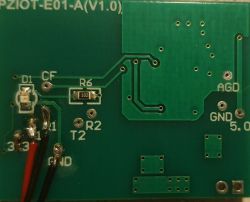
    Wait, maybe it's a false alarm, they just go to RX and TX pads, right? Nowhere else?
    Tuya Single Phase Energy Meter 6 In 1: CBU Chip Flashing & ESPHome Integration Issues
    Please confirm, if yes, then we're ready to go and I will give you my guide...
    Helpful post? Buy me a coffee.
  • ADVERTISEMENT
  • #69 20360891
    deanfourie
    Level 6  
    They go nowhere.

    They are not connected to the BL0942 and also do not connect anywhere on the ribbon cable.
  • #70 20360900
    p.kaczmarek2
    Moderator Smart Home
    That;s good, ok I will draw you an instruction.

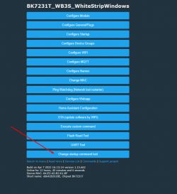
    But again, I emphasize, you must double check my proposed steps with docs (make sure that I didn't confuse pins).

    Ok, drawing, wait..

    Dodano po 1 [minuty]:

    By the way, since you will be connecting UART programmer to second device, can you this time please do first full 2MB flash read so we have a backup and can use it to do OTA flashing of next pieces?
    You have a "read" command to make "mybackup.bin" on the first page of the topic.
    Helpful post? Buy me a coffee.
  • #71 20361836
    deanfourie
    Level 6  
    Sorry I didn't see your edit.

    I can, but it is of the new firmware, I flashed all the devices already ;(
  • #72 20362003
    TurkeyMan
    Level 3  
    Oh wow, what a saga!
    I just posted a teardown for this device: https://www.elektroda.com/rtvforum/topic3945667.html#20361991
    I think mine is concise.

    I got through the first page and you didn't lift the green sticker, I'm just sitting here kicking myself! :P
    BL0942 is connected by SPI. Wiring is noted in my thread above.
    If you can advise how to configure BL0942 for SPI, then this device will work. I'm guessing it's not yet supported?

    Added after 9 [minutes]:

    Oh, upon closer inspection, I see your plan is to convert this to use UART instead of SPI...
    That seems like a bad plan rather than adding SPI support, because any future users will have a lot more problems converting their devices. Why do you consider that a better option than adding SPI support? This is an extremely common chip these days. I'm seeing it in heaps of things. This will come up again...

    I'd really prefer to keep auxiliary devices off of UART if possible, since random chips on the UART bus prohibit easily flashing the device any more without having to make modifications. It's really annoying when devices use UART. It's great this uses SPI instead.
  • #73 20362026
    p.kaczmarek2
    Moderator Smart Home
    TurkeyMan wrote:

    Oh, upon closer inspection, I see your plan is to convert this to use UART instead of SPI...
    That seems like a bad plan rather than adding SPI support, because any future users will have a lot more problems converting their devices. Why do you consider that a better option than adding SPI support? This is an extremely common chip these days. I'm seeing it in heaps of things. This will come up again...

    SPI BL0942 support is something that is hard to do remotely. I would need to have that device at hand, and so far, we have a single one SPI BL0942 device for almost 200 devices described here: https://openbekeniot.github.io/webapp/devicesList.html

    Doing reroute to UART is a faster for now, as this modification IMHO takes 5 minutes and it's done.

    @deanfourie I will prepare instruction in few hours

    @TurkeyMan I might try to get SPI running soon, but I would need to test with another SPI device, I don't have BL0942... I will also need to check if I have some kind of CBU or CB3S/WB3S module that has good access to SPI pins. I will think about. I may also consider just buying this meter.
    Helpful post? Buy me a coffee.
  • #74 20362037
    TurkeyMan
    Level 3  
    Okay. So if I want it to work now, I can cut SEL from 3.3 and connect TX/RX yeah? Then set AlwaysLow appropriately and it should be working?
    Is there some way I can help get SPI working with my device? I can probably build/run code easily enough, or I can give mine a public IP (available now) and you can OTA flash test code?
    If you can't do this easily now, it's probably something you should consider... remote run/log/debug external devices will let you access hundreds of devices from people with exotic hardware.
  • #75 20362065
    p.kaczmarek2
    Moderator Smart Home
    Wait, @TurkeyMan . I am creating a bit more detailed instruction for that now. @deanfourie asked me to do this yesterday and instruction is almost ready, just wait a bit more.

    Remote access to your device would help, but not now, I need to get basic SPI working first. All you need is a public IP for your device.
    Helpful post? Buy me a coffee.
  • #76 20362124
    deanfourie
    Level 6  
    Hmmm, that actually could be hard as I am CGNATed.

    I could give you remote access to a machine on the LAN?
  • ADVERTISEMENT
  • #77 20362156
    TurkeyMan
    Level 3  
    deanfourie wrote:
    Hmmm, that actually could be hard as I am CGNated.

    I could give you remote access to a machine on the LAN?

    I think he was talking to me, he has access to my device now for testing. If he gets SPI working, then there's no need to modify the device.
    If you are in a hurry, then you'll have modification instructions soon...
  • #78 20362158
    deanfourie
    Level 6  
    TurkeyMan wrote:
    I think he was talking to me, he has access to my device now for testing. If he gets SPI working, then there's no need to modify the device.
    If you are in a hurry, then you'll have modification instructions soon...


    Oh cool haha sorry.
  • #79 20362181
    p.kaczmarek2
    Moderator Smart Home
    I was referring to @TurkeyMan device IP.
    SPI won't be here too quickly, I would need to first find some kind of SPI device in my drawers to get the basic SPI running, and then proceed to BL0942 support.

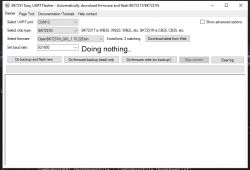
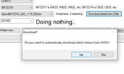
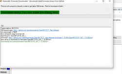
    And today I will be most likely busy with releasing BK7231T/BK7231N Easy Gui Flasher:
    Spoiler:

    Tuya Single Phase Energy Meter 6 In 1: CBU Chip Flashing & ESPHome Integration Issues
    Tuya Single Phase Energy Meter 6 In 1: CBU Chip Flashing & ESPHome Integration Issues
    Tuya Single Phase Energy Meter 6 In 1: CBU Chip Flashing & ESPHome Integration Issues

    This tool can run on modern Window machines with no Python installation required, no command line, and with everything user-friendly.
    It can automatically download OBK binary and does all flashing automatically as well, user just have to select N or T version, no command line, no offsets, etc anymore.
    Futhermore, it does automatic read (backup) of original firmware and then OBK firmware write.
    Helpful post? Buy me a coffee.
  • #81 20529840
    p.kaczmarek2
    Moderator Smart Home
    @Digga has added a BL0942SPI driver to OpenBeken. OBK now supports BL0942 in SPI mode.
    See: [BK7231N / CBU] PZIOT-E01 DIN rail pass-through energy meter
    Helpful post? Buy me a coffee.
  • #82 20534626
    p.kaczmarek2
    Moderator Smart Home
    Unlocked per user request.

    @deanfourie , have you tried new BL0942SPI driver for OpenBeken?
    Helpful post? Buy me a coffee.
  • #83 20535054
    spin55
    Level 17  
    p.kaczmarek2 wrote:
    @Digga has added a BL0942SPI driver to OpenBeken. OBK now supports BL0942 in SPI mode.
    See: [BK7231N / CBU] PZIOT-E01 DIN rail pass-through energy meter


    Great news!!!!
  • #84 20535476
    deanfourie
    Level 6  
    Excellent, my door stops can now be used as power meters.

    Could you walk me through how to implement this?

    Thanks
  • #85 20535543
    p.kaczmarek2
    Moderator Smart Home
    It seems that the first step is to put startDriver BL0942SPI in the short startup command and reboot. Then check, are you getting anything on GUI?
    Helpful post? Buy me a coffee.
  • #86 20535560
    deanfourie
    Level 6  
    Great thanks!

    Is there a detailed write-up or some instructions for the less intelligent ;P

    Cheers
  • #87 20535564
    p.kaczmarek2
    Moderator Smart Home
    This driver is very new, so there may be missing parts in the documentation.

    But if you open Web Application, and go to Tools, you will get calibration form.

    Do you know how calibration works in Tasmota?

    Basically you take good quality power meter, take 60W bulb, take the reading of the power from the good quality meter, and enter "PowerSet <YourResult>" to the console. In this case you can also use the form from the Web App so you don't have to type commands in console.... same for voltage, current...
    Helpful post? Buy me a coffee.
  • #88 20535568
    deanfourie
    Level 6  
    Hmmm yeah nah, but I'm sure I can cope with that.

    Can I at least just get the unit online and reporting data first? Or is calibration part of the flashing process?

    Thanks again!
  • #89 20535573
    p.kaczmarek2
    Moderator Smart Home
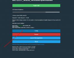
    Ah, sorry, so you haven't got the startDriver BL0942SPI command yet?

    You can enter it here:
    Tuya Single Phase Energy Meter 6 In 1: CBU Chip Flashing & ESPHome Integration Issues
    Tuya Single Phase Energy Meter 6 In 1: CBU Chip Flashing & ESPHome Integration Issues
    Tuya Single Phase Energy Meter 6 In 1: CBU Chip Flashing & ESPHome Integration Issues
    and reboot
    Helpful post? Buy me a coffee.
  • #90 20537141
    deanfourie
    Level 6  
    OK excellent,

    I'll look at this tonight :)

    Added after 2 [minutes]:

    Are there any hardware modifications that need to be performed?

    Thanks

Topic summary

The discussion centers on the Tuya Single Phase Energy Meter 6 In 1 featuring a CBU chip based on the BK7231N platform, focusing on challenges with flashing the firmware and integrating the device with ESPHome. Initial attempts to flash the device using common tools like bkWriter failed; the recommended method involves using the hid_download_py tool for flashing and backing up firmware via UART. The device uses a BL0942 power measurement chip operating in SPI mode, complicating direct UART communication. To enable easier integration, a hardware modification is proposed to reroute BL0942 from SPI to UART by cutting and reconnecting specific traces, including disconnecting the SEL pin from VDD to switch BL0942 to UART mode. Alternatively, recent firmware updates have introduced a BL0942SPI driver in OpenBeken, allowing native SPI support without hardware modifications. Calibration involves using a known power load and adjusting voltage, current, and power settings via the web interface. MQTT integration with Home Assistant is possible but requires manual YAML configuration due to limited autodiscovery support. The device measures current inductively via a non-invasive sensor coil, and the CBU module handles Wi-Fi connectivity and firmware management. Users report issues with duplicate MAC addresses and MQTT entities showing only as switches, which can be resolved by proper configuration and firmware updates. The community provides detailed guidance on flashing procedures, hardware probing, and software configuration to achieve stable operation and full sensor data reporting.
Summary generated by the language model.
ADVERTISEMENT