Elektroda.com
Elektroda.com
X

[BL602] Elivco smart plug with energy monitor BL0937 RMC004

sverd2 4776 53
  • #31
    p.kaczmarek2
    Moderator Smart Home
    Follow the guide and just ask here if any question arises.

    It should work, maybe the pinout will be different, but the QFN package of BL602 is well documented so you can just investigate the tracks on the PCB to locate RX, TX, etc...
  • #32
    viol_ten0q
    Level 6  
    okay, so I tried to disassemble the whole thing and it seems like without a hot air station, it's going to be impossible to work it. May I ask again about changing the chip altogether? I can destructively remove BL602 with my current soldering setup but would like to replace it with another chip if possible. What options do I have?
  • #33
    p.kaczmarek2
    Moderator Smart Home
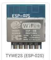
    It's the same pinout as TYWE2S, so ESP02 will most likely match, but may require soldering an extra resistor or two, I am not sure.
    [BL602] Elivco smart plug with energy monitor BL0937 RMC004
    Still, I'd suggest to try flashing BL602 first.
  • #34
    viol_ten0q
    Level 6  
    p.kaczmarek2 wrote:
    It's the same pinout as TYWE2S, so ESP02 will most likely match, but may require soldering an extra resistor or two, I am not sure.
    [BL602] Elivco smart plug with energy monitor BL0937 RMC004
    Still, I'd suggest to try flashing BL602 first.


    Thank you for the info and encouragement. I was able to wiggle the bl602 board out with some elbow grease.. now I just need to properly install the wires. Will report back with the results.
  • #35
    p.kaczmarek2
    Moderator Smart Home
    Hmmm why not just desolder the whole board? We have tutorial where we've desolder the module of the same shape... not BL602 but physically the same board:


  • #36
    viol_ten0q
    Level 6  
    p.kaczmarek2 wrote:
    Hmmm why not just desolder the whole board? We have tutorial where we've desolder the module of the same shape... not BL602 but physically the same board:


    Oh I did desolder the whole board out... the board was attached to the plug terminals by solder. It didn't help me get access to the pads on the back though by the way it was set up.

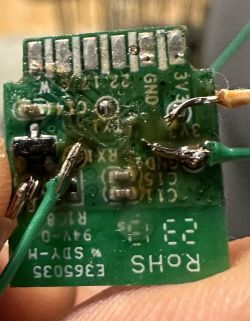
    I was able to solder 5 wires (4 in the picture - pls don't judge me on the solder job :) ) to the back side of the module, now I likely need to solder two wires to the bottom of the module for power and ground since the ones on the back will be used to set boot pin to high?

    I also realised that I don't have a USB to TTL adapter so I want to order some from Aliexpress. Do you have a suggestion as to which one should I get?
    [BL602] Elivco smart plug with energy monitor BL0937 RMC004
  • #37
    p.kaczmarek2
    Moderator Smart Home
    viol_ten0q wrote:

    I was able to solder 5 wires (4 in the picture - pls don't judge me on the solder job :) ) to the back side of the module, now I likely need to solder two wires to the bottom of the module for power and ground since the ones on the back will be used to set boot pin to high?

    I am not sure what do you mean - you need to solder 5 wires in total, there is no need to solder VDD and GND twice.

    viol_ten0q wrote:

    I also realised that I don't have a USB to TTL adapter so I want to order some from Aliexpress. Do you have a suggestion as to which one should I get?
    [BL602] Elivco smart plug with energy monitor BL0937 RMC004

    I am using CH340, the one with voltage levels selection
  • #38
    viol_ten0q
    Level 6  
    p.kaczmarek2 wrote:

    I am not sure what do you mean - you need to solder 5 wires in total, there is no need to solder VDD and GND twice.


    https://youtu.be/bs0ylC6xRs0

    In this video, it looks like the vcc and boot on the back were connected via a resistor and the main power supply was used to power the module itself?
  • #39
    p.kaczmarek2
    Moderator Smart Home
    This is because main power supply was 12V there and I needed to get 3.3V to connect to boot via resistor. In your case, there is 3.3V everywhere so there is no need for separate connection.
  • #40
    viol_ten0q
    Level 6  
    p.kaczmarek2 wrote:
    This is because main power supply was 12V there and I needed to get 3.3V to connect to boot via resistor. In your case, there is 3.3V everywhere so there is no need for separate connection.


    So I can just connect boot to vcc and connect that wire to the adapter’s 3v3?
  • #42
    viol_ten0q
    Level 6  
    p.kaczmarek2 wrote:
    I am always connecting boot to vcc via 10k resistor, just to be sure, but apart from that, yes.


    Cool thank you. Ill do that after the adapters arrive and will report back here.
  • #43
    p.kaczmarek2
    Moderator Smart Home
    Well, there are other options, if you are in hurry. Do you maybe happen to have Arduino or NodeMCU available? That could be used as USB to UART bridge.
  • #44
    viol_ten0q
    Level 6  
    p.kaczmarek2 wrote:
    Well, there are other options, if you are in hurry. Do you maybe happen to have Arduino or NodeMCU available? That could be used as USB to UART bridge.


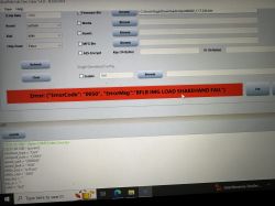
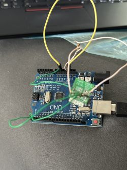
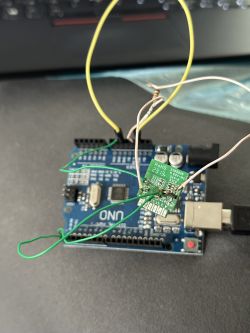
    Nice. I was able to use Arduino as the usb-ttl adapter but now getting errors trying to flash the chip using bldevcube

    attaching pictures of connections and log from the utility.

    [BL602] Elivco smart plug with energy monitor BL0937 RMC004 [BL602] Elivco smart plug with energy monitor BL0937 RMC004 [BL602] Elivco smart plug with energy monitor BL0937 RMC004

    I have made sure using continuity check that all the wires are attached as they should be.
  • #45
    p.kaczmarek2
    Moderator Smart Home
    I am not BL602 expert but I get that error when connection is wrong. So...
    - try to swap RX with TX
    - make sure that Boot is pulled high when you connect VDD (if you connect VDD first, and then pull boot high, it won't work)
    - try lower baud rate
    - try to shorten your wires
    - make sure that 3.3V is connect to the chip (if there is no power, it won\'t flash)
  • #46
    viol_ten0q
    Level 6  
    p.kaczmarek2 wrote:
    I am not BL602 expert but I get that error when connection is wrong. So...
    - try to swap RX with TX
    - make sure that Boot is pulled high when you connect VDD (if you connect VDD first, and then pull boot high, it won't work)
    - try lower baud rate
    - try to shorten your wires
    - make sure that 3.3V is connect to the chip (if there is no power, it won\'t flash)


    So, I broke one of the chips when I ripped the boot pad off so that went in the trash. I disassembled another same model ewelink plug and soldered wires again.. this time I was able to do it without having to take the module out.

    - Tried swapping rx and tx as there were suggestions on this forum elsewhere to do so.. didn't work.
    - I have taken off the insulation of the 3v3 wire in the middle and connected it BOOT wire with a 10k resistor in between, so a single wire goes into 3v3 in Arduino. That is correct, yeah?
    - lowered baud rate to 57600 as suggested by some PineCone forum
    - I shortened the wires by a few cms for the soldering on the new chip
    - didn't get you there.. how do I ensure that? If it helps, 3v3 on module is connected to 3v3 on Arduino and the chipset's LED is blinking.
  • #48
    viol_ten0q
    Level 6  
    p.kaczmarek2 wrote:
    is the Atmega on Arduino put into RESET state?


    Yeah I connected RESET with GND as was mentioned in the guides to turn Arduino to USB-TTL adapter. I guess I will have to wait for the proper TTL converter to give it another shot...
  • #49
    p.kaczmarek2
    Moderator Smart Home
    Hmm... disconnect boot from VDD, then reconnect power. Are you getting anything on UART? You should get a debug log from original BL602 firmware.
  • #50
    viol_ten0q
    Level 6  
    p.kaczmarek2 wrote:
    Hmm... disconnect boot from VDD, then reconnect power. Are you getting anything on UART? You should get a debug log from original BL602 firmware.


    When I press “Log” in the DevCube window it still throws errors “file not available” etc I tried a different arduino nano - didn’t work. Resoldered wires, changed rx tx etc but no luck. Tried to do it without boot attached to 3v3 and then it attached without the resistor but no luck there either. Could it also be that this new setup where the module is still installed in the mainboard is creating issues? That it’s somehow shorting some pins down the line etc?
  • #51
    viol_ten0q
    Level 6  
    While I was waiting for the UART USB converter from Ali, I found that the Flipper Zero I had also can be used as a ttl converter. I used that and it flashed successfully! Currently waiting for the glue to dry to actually plug the plug and see if it works.

    Thanks for the help.
  • #52
    p.kaczmarek2
    Moderator Smart Home
    Well, Flipper Zero is certainly the most expensive USB to UART converter I've heard about, but as it looks like it also does the trick. So, good job, keep us updated, I will try to help if any issue arise.
  • #53
    viol_ten0q
    Level 6  
    Haha yeah it’s expensive but I had it already so just one more use for it.

    Unfortunately after successful flash, I removed all the soldered wires and then plugged the socket into the outlet but I never got the openbeken AP. Now I’m banging my head against the desk for taking the wires off too soon. Will try to solder them on again and see if I can still detect and reflash or if I killed the chip again. :)
  • #54
    p.kaczmarek2
    Moderator Smart Home
    The BL602 UART port is used for both flashing and debug log output, so if you keep programmer connected you can see what's going on and detect any potential issues early.

    The BK7231 platform is different in that manner, on BK7231 you have UART1 for flashing and separate UART2 for debug log.