logo elektroda
logo elektroda
X
logo elektroda

[BL602] Elivco smart plug with energy monitor BL0937 RMC004

sverd2 21636 84
ADVERTISEMENT
  • #61 20909904
    atomiquepingouin
    Level 4  
    i have accidentally remove pin. i've scratched pcb but i'm not sure is good
  • ADVERTISEMENT
  • #62 20909965
    p.kaczmarek2
    Moderator Smart Home
    Can you show a photo? Do you have IPA to clean the PCB?
    Helpful post? Buy me a coffee.
  • ADVERTISEMENT
  • #63 20910031
    atomiquepingouin
    Level 4  
    yes i have IPA (but i don't like beer /j). Close-up of a small green circuit board with electronic components. Close-up of a circuit board with markings B and T.
  • ADVERTISEMENT
  • #64 20912402
    p.kaczmarek2
    Moderator Smart Home
    That looks hard. I could try to help, but you're not from Poland, aren't you?
    Helpful post? Buy me a coffee.
  • ADVERTISEMENT
  • #65 20912543
    atomiquepingouin
    Level 4  
    I come from France. Do you think I can solder directly on R2? Close-up of a PCB with the R2 component highlighted.
  • #66 20912564
    p.kaczmarek2
    Moderator Smart Home
    Hey, so that's the same trace that's BOOT pin? Of course you can. This is a very good solution, I must admit I have assumed that there are no futher solder points when I read your message.
    Helpful post? Buy me a coffee.
  • #68 20915287
    atomiquepingouin
    Level 4  
    hi after resoldering the socket does not light up. i have use web application for config
  • #69 20915506
    p.kaczmarek2
    Moderator Smart Home
    Can you provide any more information, what do you mean by "does not light up"?
    Helpful post? Buy me a coffee.
  • #70 20915860
    atomiquepingouin
    Level 4  
    the LED does not light up and neither does the relay. I have no current between phase and neutral and no change when I press the button
  • #71 20916559
    p.kaczmarek2
    Moderator Smart Home
    Excuse me, did you configure the GPIO for your device after flashing? You know, you need to set a relay role for a proper GPIO first before the device can work.
    Helpful post? Buy me a coffee.
  • #72 20916727
    atomiquepingouin
    Level 4  
    yes i use web application Web application interface for configuring the Elicvo WiFi plug with a list of devices and pin settings.
  • #73 20917414
    Mad_Maxs
    Level 11  
    Hello, I bought an Elivco BSD33 socket with BL602L20 and BL0937 on Ali, on the SM-28_V1.3 board.

    Is there a chance to run reading from BL0937 in this device? After following the thread from the beginning, I know that there were some attempts, but I guess it was not possible to finish the topic.
  • #74 20917935
    p.kaczmarek2
    Moderator Smart Home
    @atomiquepingouin well, manufacturer may have changed the GPIOs used for relay and button. Please open the Web App and use GPIO Doctor to check which pins are used for relay and button in your device.

    @Mad_Maxs I'm afraid that BL0937 is still missing interrupt counter on BL602 platform: https://github.com/openshwprojects/OpenBK7231T_App/pull/862 it needs to be finished first and then BL0937 will work
    Helpful post? Buy me a coffee.
  • #75 20919651
    Mad_Maxs
    Level 11  
    What is the chance that a hero will be found in the near future who will manage it to the end? 😀 I did some coding, but I think it`s too high a level for me 😉

    In my socket, the pin from the button has changed to gpio17, but after tracing the paths, the pins from bl0937 are still valid
  • #76 20919824
    p.kaczmarek2
    Moderator Smart Home
    User @miegapele has some progress on BL602 + BL0937 combo in this thread:
    https://www.elektroda.com/rtvforum/topic4020634.html#20919632
    Helpful post? Buy me a coffee.
  • #77 20923215
    Mad_Maxs
    Level 11  
    Currently 1.17.421 version of OpenBL for 602 support BL0937. Thanks everyone, who make it happen :)

    Screenshot of a user interface showing the on state with energy information for device BL0937.
  • #78 20923291
    p.kaczmarek2
    Moderator Smart Home
    How accurate is it? I see you have 260V AC, I think you need to calibrate it first.
    Helpful post? Buy me a coffee.
  • #79 20923500
    hojnikb
    Level 11  
    p.kaczmarek2 wrote:
    How accurate is it? I see you have 260V AC, I think you need to calibrate it first.


    pretty inaccurate both in terms of current and voltage. Mine showed 265-270V while being 235V, amps were off by at least 10-15% too.
  • #80 20923577
    p.kaczmarek2
    Moderator Smart Home
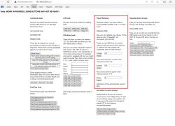
    Yea, but did you calibrate? This is a necessary step. Calibration is done like in Tasmota, via VoltageSet, etc, commands, but you also have a GUI wrapper for that at Open Web App -> Tools Tab, here:
    Screenshot of a configuration interface for power metering tools with a calibration section.
    So let me ask you again - did you calibrate your devices, guys? @hojnikb @Mad_Maxs
    Helpful post? Buy me a coffee.
  • #81 20923833
    hojnikb
    Level 11  
    p.kaczmarek2 wrote:
    Yea, but did you calibrate? This is a necessary step. Calibration is done like in Tasmota, via VoltageSet, etc, commands, but you also have a GUI wrapper for that at Open Web App -> Tools Tab, here:
    Screenshot of a configuration interface for power metering tools with a calibration section.
    So let me ask you again - did you calibrate your devices, guys? @hojnikb @Mad_Maxs


    Yep, absolutly, did a calibration via resistive load (halogen lamp) against a decent power meter. Now it's showing almost bang on.
  • #82 20924584
    Mad_Maxs
    Level 11  
    p.kaczmarek2 wrote:

    So let me ask you again - did you calibrate your devices, guys? @hojnikb @Mad_Maxs

    Of course i didn't :) that's why it shows 260V. After calibration, looks like measuring is correct
  • #83 20924653
    p.kaczmarek2
    Moderator Smart Home
    Calibration is necessary to get useable results. All those devices are calibrated per-piece in factory.
    Helpful post? Buy me a coffee.
  • #84 20927224
    atomiquepingouin
    Level 4  
    @p.kaczmarek2 hi after two days the socket no longer starts and when I connect to it I only have this Text OpenBL602_4CA573CD on a gray background I reflash but it's still the same
  • #85 21016900
    Raufaser
    Level 10  
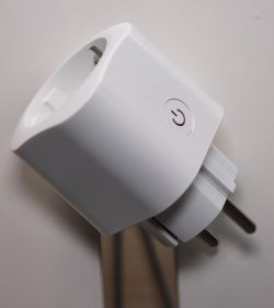
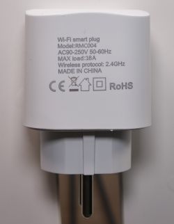
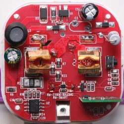
    I got an RMC004 with BL602 from Aliexpress. But it has red main PCB. I guess a different revision. There is for example C3 missing on my board. So I thought why not take a few pictures and document my way to flashing the smart plug:

    Smart plug with power button at an angle. White Wi-Fi smart plug with model RMC004 markings.

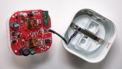
    Unscrew the neutral cable from the PCB holder:

    Red PCB with relays and electronic components inside a smart plug housing. Red RMC004 circuit board with electronic components.

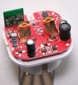
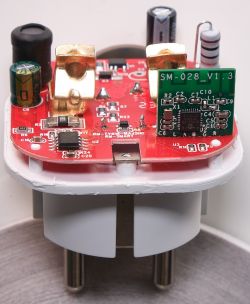
    Beautiful views of the communication PCB in its place on the main PCB:
    Close-up of a red circuit board with electronic components and relays. Close-up of a red PCB smart plug labeled SM-028_V1.3 with attached electronic components.

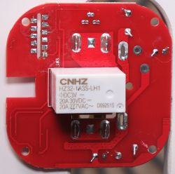
    Desoldering the main PCB from the PCB-Holder/Plug lets you view the relais:
    Red printed circuit board with a component labeled CNHZ HZ32-1A3S-LH1.
    It's always nice to have a 20A relais in a 16A socket :)

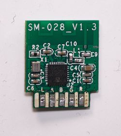
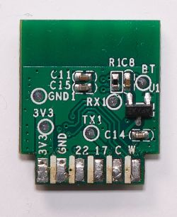
    And here is the BL602 board:
    SM-028 circuit board version 1.3 with electronic components. BL602 PCB with component markings.

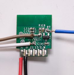
    And this is how i soldered the wires to flash this little guy:
    Close-up of a BL602 PCB with soldered wires.
    The only special thing is the blue wire must be pulled high. In line with 10kOhm to 3,3V

    Before I flashed OpenBeken i dumped the original firmware using this tool.
    BL602_0x10...150000.zip Download (554.75 kB)

    Flashing worked like normal. And here is my config:

    {
      "vendor": "Tuya",
      "bDetailed": "0",
      "name": "Wi-Fi smart plug",
      "model": "RMC004",
      "chip": "BL602",
      "board": "SM-028_V1.3",
      "flags": "1024",
      "keywords": [
        "power metering",
        "smart plug",
        "bl0937"
      ],
      "pins": {
        "2": "Rel;1",
        "3": "BL0937CF1;0",
        "14": "BL0937CF;0",
        "20": "LED_n;1",
        "21": "BL0937SEL;0",
        "22": "Btn;1"
      },
      "command": "backlog startDriver BL0937; startDriver NTP",
      "image": "https://obrazki.elektroda.pl/8014289700_1711242720.jpg",
      "wiki": "https://www.elektroda.com/rtvforum/viewtopic.php?p=21016900#21016900"
    }

Topic summary

The discussion revolves around the Elivco smart plug model RMC004, which incorporates a BL602 microcontroller and a BL0937 energy monitoring IC. Users report challenges with the energy monitoring functionality, primarily due to the absence of a necessary interrupt counter in the BL602 driver for the BL0937. Some users have successfully opened the plug and attempted to modify the firmware, while others have suggested replacing the BL602 with an ESP-02S module for better compatibility. Calibration of the energy monitoring feature is also highlighted as essential for accurate readings. Recent updates indicate that the OpenBL602 firmware now supports the BL0937, although users still report issues with accuracy and functionality. Various methods for opening the plug and flashing the firmware are discussed, including using Arduino as a USB-TTL adapter and troubleshooting connection issues.
Summary generated by the language model.
ADVERTISEMENT