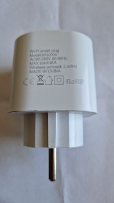
Bought a Wifi smart plug from AliExpress which seems to be of the Elivco brand, model number RMC004.
![[BL602] Elivco smart plug with energy monitor BL0937 RMC004 [BL602] Elivco smart plug with energy monitor BL0937 RMC004](https://obrazki.elektroda.pl/2716546900_1672313095_thumb.jpg)
![[BL602] Elivco smart plug with energy monitor BL0937 RMC004 [BL602] Elivco smart plug with energy monitor BL0937 RMC004](https://obrazki.elektroda.pl/1556106400_1672313255_thumb.jpg)
![[BL602] Elivco smart plug with energy monitor BL0937 RMC004 [BL602] Elivco smart plug with energy monitor BL0937 RMC004](https://obrazki.elektroda.pl/5702679100_1672313259_thumb.jpg)
![[BL602] Elivco smart plug with energy monitor BL0937 RMC004 [BL602] Elivco smart plug with energy monitor BL0937 RMC004](https://obrazki.elektroda.pl/6312879400_1672313264_thumb.jpg)
![[BL602] Elivco smart plug with energy monitor BL0937 RMC004 [BL602] Elivco smart plug with energy monitor BL0937 RMC004](https://obrazki.elektroda.pl/7513442600_1672313267_thumb.jpg)
![[BL602] Elivco smart plug with energy monitor BL0937 RMC004 [BL602] Elivco smart plug with energy monitor BL0937 RMC004](https://obrazki.elektroda.pl/3052594300_1672313272_thumb.jpg)
![[BL602] Elivco smart plug with energy monitor BL0937 RMC004 [BL602] Elivco smart plug with energy monitor BL0937 RMC004](https://obrazki.elektroda.pl/4227446800_1672313276_thumb.jpg)
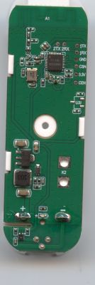
Opening the plug is relatively straightforward. In order to get the PCB off the plug I had to de-solder it from the 2 connections to the pins of the plug. After that the PCB with relay could easily be removed.
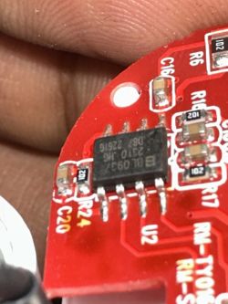
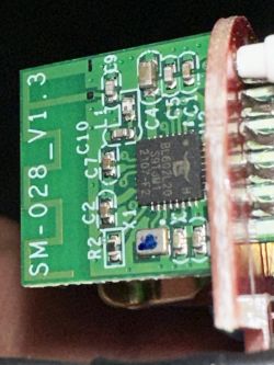
Closer inspection showed that the plug contained a BL602 board and a BL0937 IC for the energy monitoring. The power for the PCB seems to be supplied by a BP2525 IC. (I was unable to get the IC markings clearly visible on the pictures, using magnification the markings were clearly visible).
Another thing to notice is that the relay seems to be for 16A max whereas the plug is rated for 20A max. As a result I think the plug should not be used with >16A, or am I overseeing something there?
Flashing with the BL602 firmware seems to work, but configuration is necessary and at this moment the BL0937 energy monitoring does not seem to function. Following the traces on the PCB and checking continuity with a multi meter I found the following "configuration":
LED: pin 29 on the BL602, so GPIO20
Relay; P2, so GPIO2
Button: pin 31 on the BL602, so GPIO22
BL0937 CF1: pin4 on the BL602, so GPIO3
BL0937 CF: pin 22 on the BL602, so GPIO14
BL0937 SEL: pin 30 on the BL602 so GPIO21
as mentioned above at this moment this pin assignments work for LED, relay and button, but the BL0937 does not show up at all.
Cool? Ranking DIY


![[BL602] Elivco smart plug with energy monitor BL0937 RMC004 [BL602] Elivco smart plug with energy monitor BL0937 RMC004](https://obrazki.elektroda.pl/9271543200_1681999519_thumb.jpg)
![[BL602] Elivco smart plug with energy monitor BL0937 RMC004 [BL602] Elivco smart plug with energy monitor BL0937 RMC004](https://obrazki.elektroda.pl/4970128100_1681999520_thumb.jpg)
![[BL602] Elivco smart plug with energy monitor BL0937 RMC004 [BL602] Elivco smart plug with energy monitor BL0937 RMC004](https://obrazki.elektroda.pl/2562790800_1686761969_thumb.jpg)
![[BL602] Elivco smart plug with energy monitor BL0937 RMC004 [BL602] Elivco smart plug with energy monitor BL0937 RMC004](https://obrazki.elektroda.pl/7721952100_1686771282_thumb.jpg)
![[BL602] Elivco smart plug with energy monitor BL0937 RMC004 [BL602] Elivco smart plug with energy monitor BL0937 RMC004](https://obrazki.elektroda.pl/9606527600_1686771312_thumb.jpg)
![[BL602] Elivco smart plug with energy monitor BL0937 RMC004 [BL602] Elivco smart plug with energy monitor BL0937 RMC004](https://obrazki.elektroda.pl/9634053100_1687622027_thumb.jpg)


