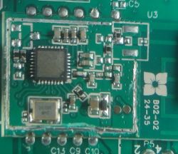
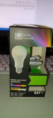
Hello, the first step is to determine whether it's possible to control your colours by raw PWMs, with no "i2c" drivers.
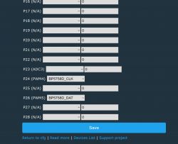
BK7231 has 6 possible PWM pins:
| PWM0 | I/O | GPIOP_6, which is connected to the P6 pin on the internal IC |
PWM1 | I/O | GPIOP_7, which is connected to the P7 pin on the internal IC | PWM2 | I/O | GPIOP_8, which is connected to the P8 pin on the internal IC | PWM3 | I/O | GPIOP_9, common GPIO, which is connected to the P9 pin on the internal IC | PWM4 | I/O | GPIOP_24, common GPIO, which is connected to the P24 pin on the internal IC | PWM5 | I/O | GPIOP_26, which is connected to the P26 pin on the internal IC |
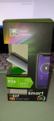
Considering that your bulb is RGBCW (so it requires 5 PWMs), if you set 5 of those pins roles to PWM, you
should get some control and then you can work from there, see which channels are swapped.
Please try. Or just apply some random PWM-based bulb template in Web App.
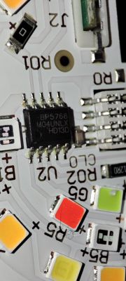
Then double check - are you able to get any light at all? If no, then we can start worrying and assume that your bulb is using a custom "i2c" driver like SM2135 or SM2235.
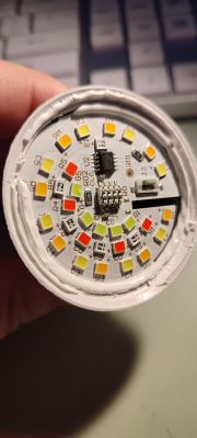
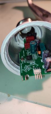
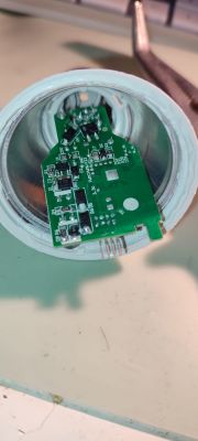
But it doesn't look like it - your photo is showing that there is 2x4 gold pin header going to LED board. That's whole 8 signals! So many signals are usually not needed for "i2c" drivers, that would suggest your LED is using just simply PWMs.
