logo elektroda
logo elektroda
X
logo elektroda

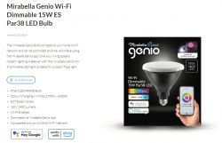
Mirabella Genio Wi-Fi Dimmable 15W ES Par38 LED Bulb - Teardown

wolfieeewolf 1395 7
ADVERTISEMENT
  • Device Name: Mirabella Genio Wi-Fi Dimmable LED Bulb
    Device Type: 15W ES Par38
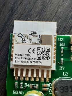
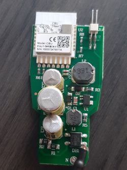
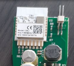
    Device Chip: CBU - BK7231N
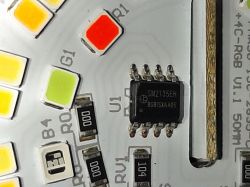
    Device U1 Chip: SM2135EH - BGBISYAA05
    Device Purchased: Bunnings Warehouse - $25AUD
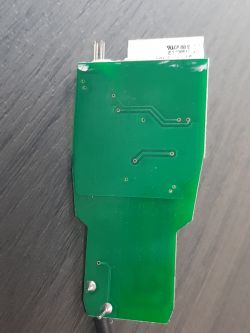
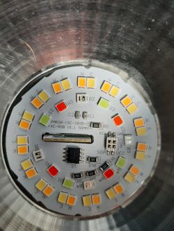
    Mirabella Genio Wi-Fi Dimmable 15W ES Par38 LED Bulb - Teardown Mirabella Genio Wi-Fi Dimmable 15W ES Par38 LED Bulb - Teardown Mirabella Genio Wi-Fi Dimmable 15W ES Par38 LED Bulb - Teardown Mirabella Genio Wi-Fi Dimmable 15W ES Par38 LED Bulb - Teardown Mirabella Genio Wi-Fi Dimmable 15W ES Par38 LED Bulb - Teardown Mirabella Genio Wi-Fi Dimmable 15W ES Par38 LED Bulb - Teardown

    Flashing of Main Chip

    CloudCutter Profile - oem-bk7231n-light-ty-1.2.7-sdk-2.3.1-40.00.json

    I created a CloudCutter profile using LightLeak.
    I attempted to flash several times but was unsuccessful. It would get to loading the new firmware but appeared to have trouble uploading it. It could have been an error on my end or an issue with the LightLeak profile I created. After many fail attempts I ended up manually flashing the chip with BK7231 GUI Flash Tool. It worked first try.

    CBU Module Datasheet

    Configuration of Module

    Mirabella Genio Wi-Fi Dimmable 15W ES Par38 LED Bulb - Teardown

    Light working as expected. If RGB colours are wrong use SM2135_Map

    You can enter this command on the Logs tab in the "Command" box. Hit submit and it should update the colour map. I understand that the config with stay with any updates going forward. Will update this post if that is not the case.

    My light colours before setting the SM2135_Map was

    Red = Blue
    Blue = Green
    Green = Red
    Warm White = Cool White
    Cool White = Warm White

    enter - SM2135_Map 0 1 2 4 3 - This should fix the issue.

    Setting Flag 18 also helps with smoother transitions.

    I believe there is a Music/Disco mode that works on the Mirabella Genio app. I haven't bothered to work this one out as it's not a function I'd ever use. Feel free to give it a go if that is what you need.

    Cool? Ranking DIY
    About Author
    wolfieeewolf
    Level 11  
    Offline 
    wolfieeewolf wrote 92 posts with rating 18, helped 6 times. Been with us since 2023 year.
  • ADVERTISEMENT
  • Helpful post
    #2 20462639
    p.kaczmarek2
    Moderator Smart Home
    Hello, what is the marking of U1 chip? It looks like modified I2C LED controller, with those SDA/SCL markings on the board...

    There is no sense in setting PWMs, as it can be clearly seen that the LED boards is getting 4 signals, one is power, one is ground, so it would leave space only for 2 PWMs and it's RGBCW, so it has just not enough pins.

    It must by SM2135 or similiar.
    Helpful post? Buy me a coffee.
  • ADVERTISEMENT
  • #3 20463817
    wolfieeewolf
    Level 11  
    I uploaded a picture of the U1. It's a SM2135EH - BGBISYAA05. Also looking at the LED's they appear to be SM2835's. Not sure if that makes any difference. I have tried setting the SM2135DAT and CLK to the pins 7 and 8 also pin 24 and 26 as they are the pins the other Mirabella devices have been using. No luck as of yet. I'm sure it's just a pin allocation issue as the other devices had a different firmware chip and it's a matter of just trying all combinations until I get it. I'll just keep trying until I find the magical pin combo for now unless you have a better idea.
  • #4 20463838
    p.kaczmarek2
    Moderator Smart Home
    Please do not try at random. When you look at this photo:
    Mirabella Genio Wi-Fi Dimmable 15W ES Par38 LED Bulb - Teardown
    you can easily see which pins to access and test with multimeter. Just use continuity test mode and check which CBU pins are used for I2C communication.

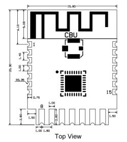
    Here is CBU pinout:
    Mirabella Genio Wi-Fi Dimmable 15W ES Par38 LED Bulb - Teardown
    Pin numberSymbolI/O typeFunction
    1P14I/OCommon GPIO, which can be reused as SPI_SCK (Correspond to Pin 11 of the IC)
    2P16I/OCommon GPIO, which can be reused as SPI_MOSI (Correspond to Pin 12 of the IC)
    3P20I/OCommon GPIO (Correspond to Pin 20 of the IC)
    4P22I/OCommon GPIO (Correspond to Pin 18 of the IC)
    5ADCI/OADC, which corresponds to P23 on the internal IC (Correspond to Pin 17 of the IC)
    6RX2I/OUART_RX2, which corresponds to P1 on the internal IC. (Correspond to Pin 28 of the IC)
    7TX2I/OUART_TX2, which is used for outputting logs and corresponds to P0 of the internal IC (Correspond to Pin 29 of the IC)
    8P8I/OSupport hardware PWM (Correspond to Pin 24 of the IC)
    9P7I/OSupport hardware PWM (Correspond to Pin 23 of the IC)
    10P6I/OSupport hardware PWM (Correspond to Pin 22 of the IC)
    11P26I/OSupport hardware PWM (Correspond to Pin 15 of the IC)
    12P24I/OSupport hardware PWM (Correspond to Pin 16 of the IC)
    13GNDPPower supply reference ground
    143V3PPower supply 3V3
    15TX1I/OUART_TX1, which is used for transmitting user data and corresponds to Pin 27 of the IC. For the MCU solution, please refer to CBx Module.
    16RX1I/OUART_RX1, which is used for receiving user data and corresponds to Pin 26 of the IC. For the MCU solution, please refer to CBx Module.
    17P28I/OCommon GPIO (Correspond to Pin 10 of the IC)
    18CENI/OReset pin, low active (internally pulled high), compatible with other modules (Correspond to Pin 21 of the IC)
    19P9I/OCommon GPIO (Correspond to Pin 25 of the IC)
    20P17I/OCommon GPIO, which can be reused as SPI_MISO (Correspond to Pin 14 of the IC)
    21P15I/OCommon GPIO, which can be reused as SPI_CS (Correspond to Pin 13 of the IC)
    Test pointCSNI/OMode selection pin. If it is connected to the ground before being powered on, enter the firmware test mode. If it is not connected or connected to VCC before being powered on, enter the firmware application mode. Correspond to Pin 19 on the internal IC.


    but on the photo, I can see that only pins 8-14 are soldered, so those are the candidates:
    8P8I/OSupport hardware PWM (Correspond to Pin 24 of the IC)
    9P7I/OSupport hardware PWM (Correspond to Pin 23 of the IC)
    10P6I/OSupport hardware PWM (Correspond to Pin 22 of the IC)
    11P26I/OSupport hardware PWM (Correspond to Pin 15 of the IC)
    12P24I/OSupport hardware PWM (Correspond to Pin 16 of the IC)
    Helpful post? Buy me a coffee.
  • ADVERTISEMENT
  • #5 20463873
    wolfieeewolf
    Level 11  
    Not really trying at random. Been sticking with these pins below as they are the only ones that I can see would be correct.

    8P8I/OSupport hardware PWM (Correspond to Pin 24 of the IC)
    9P7I/OSupport hardware PWM (Correspond to Pin 23 of the IC)
    10P6I/OSupport hardware PWM (Correspond to Pin 22 of the IC)
    11P26I/OSupport hardware PWM (Correspond to Pin 15 of the IC)
    12P24I/OSupport hardware PWM (Correspond to Pin 16 of the IC)


    I unfortunately do not own a multimeter so can't test it that way. Will have to go buy one and see what I can find. I'm kind of perplexed as there is another Mirabella device that uses pins 24 and 26 with the same SM2135 chip and it works fine. Maybe there has been some slight changes, but I would think it should still run on those pins regardless. Anyway, off to buy a multimeter and will report my findings.

    Added after 1 [minutes]:

    Finally worked it out. Has the CLK and DAT settings around the other way to the other Mirabella devices.

    Light working as expected. RGB colours at this stage are wrong.

    Red = Blue
    Blue = Green
    Green = Red
  • ADVERTISEMENT
  • Helpful post
    #6 20463993
    p.kaczmarek2
    Moderator Smart Home
    Very good job on figuring that out. It will be useful for our templates list.

    Now, do you know how to change the colour order?

    Look up SM2135_Map function.
    https://github.com/openshwprojects/OpenBK7231T_App/blob/main/docs/commands.md
    Helpful post? Buy me a coffee.
  • #7 20464037
    wolfieeewolf
    Level 11  
    Took some stuffing about but finally got there.

    Been messing with the SM2135_Map config. After much messing about with values it ends up it was just the default 0 1 2 3 4 setting.

    updating the post now.

    Thanks for your help. Would have probably taken me a day or so to crack the SM2135_Map config thing without the link you sent
  • #8 20464165
    p.kaczmarek2
    Moderator Smart Home
    We will be trying to update documentation soon so it's more detailed and better organized, but also don't forget that we have tutorials on our YT channel:
    https://www.youtube.com/@elektrodacom
    They are organized into playlists:
    https://www.youtube.com/@elektrodacom/playlists
    Helpful post? Buy me a coffee.

Topic summary

The discussion revolves around the Mirabella Genio Wi-Fi Dimmable 15W ES Par38 LED Bulb, focusing on the teardown and firmware flashing attempts. The main chip is identified as CBU - BK7231N, with a secondary SM2135EH - BGBISYAA05 chip for LED control. Users share insights on pin configurations for I2C communication and PWM settings, emphasizing the importance of correct pin allocation. After several trials, one user successfully configured the SM2135_Map settings to achieve the desired functionality. The conversation also highlights the need for better documentation and available tutorials for further assistance.
Summary generated by the language model.
ADVERTISEMENT