logo elektroda
logo elektroda
X
logo elektroda

[BK7231N] AP-SMT-Breaker02-1CH EZB-WBZS1H16N-A - 16A Mini Smart Switch 1 Channel

anthonythomas 10989 18
ADVERTISEMENT
  • Unsure if this one has been posted already.

    AP-SMT-Breaker02-1CH EZB-WBZS1H16N-A - 16A Mini Smart Switch 1 Channel
    Bought from the AliExpress Choice Day sales

    Different to a similar mini smart switch I have flashed.

    BK7231N MCU is part of the main PCB
    Relay is on a daughter PCB to rotate it

    Used tuya-cloudcutter to flash OpenBK (didn't even setup in SmartLife app - just went straight to cloudcutter)
    > By manufacturer/device name
    > Aubess
    > 16A Mini Smart Switch
    > 1.2.1 - BK7231N / oem_bk7231n_control_switch
    OpenBK7231N_UG_1.15.597.bin

    Pin settings are possibly different to other versions - these work for my device.

    LED_n 6
    Rel 15
    Btn 8
    TglChanOnTgl 14

    [BK7231N] AP-SMT-Breaker02-1CH EZB-WBZS1H16N-A - 16A Mini Smart Switch 1 Channel
    [BK7231N] AP-SMT-Breaker02-1CH EZB-WBZS1H16N-A - 16A Mini Smart Switch 1 Channel [BK7231N] AP-SMT-Breaker02-1CH EZB-WBZS1H16N-A - 16A Mini Smart Switch 1 Channel [BK7231N] AP-SMT-Breaker02-1CH EZB-WBZS1H16N-A - 16A Mini Smart Switch 1 Channel [BK7231N] AP-SMT-Breaker02-1CH EZB-WBZS1H16N-A - 16A Mini Smart Switch 1 Channel [BK7231N] AP-SMT-Breaker02-1CH EZB-WBZS1H16N-A - 16A Mini Smart Switch 1 Channel [BK7231N] AP-SMT-Breaker02-1CH EZB-WBZS1H16N-A - 16A Mini Smart Switch 1 Channel

    Cool? Ranking DIY
    About Author
    anthonythomas
    Level 9  
    Offline 
    anthonythomas wrote 39 posts with rating 14, helped 4 times. Been with us since 2023 year.
  • ADVERTISEMENT
  • #3 20530465
    mucek4
    Level 1  
    Other topic is closed, so I'll ask here. Why key and relay is set as "relay ID 1"? Why not 0? Is the unused "Relay 0" any special thing and shall not be used?
  • #4 20537140
    hmonteiro
    Level 7  
    Hello!

    I've purchased half a dozen of those, and i've confirmed they're the exact bacth, at least from the PCB printouts.
    Could you provide me with the exact version of cloudcutter you were able to flash with? I've just cloned the last git version and it's failing to setup the A-* access point after sending the exploit.

    I'm putting the device in AP mode, it finds the SmartLife AP, sends exploit but then, when i long press the button again for fast flash, and then again for slow flash, either straight away, or by actually power cycling the device, the SmartLife AP pops up again. I'm wondering if i'm doing anything wrong or i've just ran out of luck with some Aubess firmware upgrade.

    Thanks in advance.
  • #5 20539277
    riskorja
    Level 7  
    Hi, in batch of three I had one Smart Mini Switch that has the same pcb.

    With one of them I had to pair it with "cloudcutterflash" AP with internet access by using Tuya/SmartLife App to enter WiFi credentials.
    After that tuya-cloudcutter process continued.
    For the "cloudcutterflash" AP i used second/spare router.

    It is as stated in Note: of the INSTRUCTIONS.md

    I hope this helps
  • #6 20539348
    hmonteiro
    Level 7  
    Hi riskorja, thanks for your feedback.

    I'm trying to flash the device and not just disconnect it from the internet. The procedure for that is at the bottom of the page you sent, in the "Flashing custom firmware" section.
    The main difference is that the exploit will make the device associate with a custom AP, from where the new firmware will be sent OTA.
    My guess about a new vendor firmware, not vulnerable to the exploit, is because i'm not observing any freezing of the LED light.
    I have used that procedure on other devices and all i needed was my laptop (and some luck aparenty).

    Regards,

    Hugo.
  • ADVERTISEMENT
  • #7 20540494
    riskorja
    Level 7  
    Hi

    my goal was also to upload new firmware.
    As I observed the procedure, the first part changes the AP name of device SmartLife_mac to A_mac after that the light should freeze.
    I successfully tried my luck on three smart mini switches with two setups:
    - RPi with Raspberry OS an supervised HA on which tuya-cloudcutter script runs without warnings, but had to manually add "cloudcutterflash" AP WiFi credentials after first part. Tried only one device.
    - Netbook with Debian on which tuya-cloudcutter script runs with some warnings, on one device manual restart was needed, on one device the light freeze was observed.
    Luckily the script can be run multiple times, and only one device needed to add WiFi credentials manually, after that script successfully replaced the firmware to OpenBeken.

    Best Regards
    Rihard
  • ADVERTISEMENT
  • #8 20543446
    p.kaczmarek2
    Moderator Smart Home
    Some new Tuya devices are not vulnerable to Cloudcutter. Please just use soldering method to flash OpenBeken then. We have a playlist of soldering guides for uploading new firmware to smart device:
    https://www.youtube.com/playlist?list=PLzbXEc2ebpH0CZDbczAXT94BuSGrd_GoM
    Helpful post? Buy me a coffee.
  • #9 20543643
    hmonteiro
    Level 7  
    Hello p.kaczmarek2,

    Thank you so much for all your work. It's been a game changer.
    I was trying to avoid my poor soldering skills :D but i guess i'm out of luck on that.
    Keep up the good work!
  • ADVERTISEMENT
  • #10 20543734
    p.kaczmarek2
    Moderator Smart Home
    We are showing soldering process step by step on our channel, so it should be easy to replicate.
    Helpful post? Buy me a coffee.
  • #11 20557058
    karrlsson
    Level 2  
    [BK7231N] AP-SMT-Breaker02-1CH EZB-WBZS1H16N-A - 16A Mini Smart Switch 1 Channel >>20507709
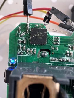
    In my experience i found out it is enough 3 wires Gnd,Tx,Rx and lower baud rate to 115200 and i had success in over 10 boards flashing. Here is image of Aubess board with BK7321N onboard, With this revision cloud cutter didnt work for me, but luckily there is easy traceable test points Yellow is RX White Tx.

    Pin 6: TglChanOnTgl on channel 1
    Pin 7: Rel on channel 1
    Pin 23: Btn on channel 1
    Pin 26: LED_n on channel 1
  • #12 20557123
    p.kaczmarek2
    Moderator Smart Home
    @karrlsson are you saying that you do not connect 3.3V?

    Well, most likely you are powering it through RX/TX then, thanks to the protection diodes of GPIO. EEVBlog had a video on that:
    https://www.youtube.com/watch?v=2yFh7Vv0Paw
    Helpful post? Buy me a coffee.
  • #13 20557138
    karrlsson
    Level 2  
    Yes i do not connect 3.3v and somehow the chip this way is in programming mode always... no CEN to ground needed. i connect 3.3v only after programming to do inital setup without mains...
    But i just found CB2S module which i cant program at all, i need to check if it was working at all...
  • #14 20557162
    p.kaczmarek2
    Moderator Smart Home
    I also found some time ago, that because of this RX/TX powering module, I sometimes have to ground the VDD of module, just to make sure it's off, in order to do a power cycle correctly.

    Still, powering without 3.3V is not recommended.

    What kind of device do you have with that CB2S?
    Helpful post? Buy me a coffee.
  • #15 20686601
    p.kaczmarek2
    Moderator Smart Home
    Here is a Polish/English review of a newer version of this switch, this time with CBU module:

    https://www.elektroda.pl/rtvforum/topic3994713.html#20686595
    https://www.elektroda.com/rtvforum/topic3994713.html#20686595
    Helpful post? Buy me a coffee.
  • #16 20965496
    chuc2rk
    Level 1  
    >>20507709
    thank you for pin config.
  • #17 21035919
    aliexpress
    Level 4  
    Hi,

    I have just received a different version of the AP-SMT-Breaker02-1CH from our favorite Chinese vendor.
    Will not work with cloudcutter.
    Unfortunately, they mounted all components (except LED and switch) on the top side of the PCB.
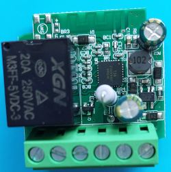
    This means, the T34 chip is surrounded basically by all the components that are very high (relais, resistor, capacitor, coil).
    Unfortunately, there is not a single pad for pogo pins.

    Any idea on how to flash that? Due to the surrounding by 3D "high" components, it seems impossible to get directly to Pins 25/26 of the T34 for serial connection. I am lost!
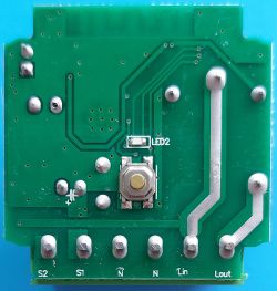
    Gray PCB with various electronic components, including a relay, capacitor, and T34 integrated circuit. Bottom view of the AP-SMT-Breaker02-1CH PCB with a button and terminals.
  • #18 21036043
    p.kaczmarek2
    Moderator Smart Home
    That looks like a true challenge. It's a shame that I don't get that kind of devices myself.

    Unfortunatelly the only viable solution I can see is the one described here:
    [BK7231N / T34 ] Teardown Tuya Generic Wifi Wall Light Switch 3 Gang
    CameronDev wrote:
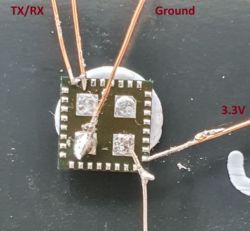
    Close-up of a small electronic board with thin wires soldered and labeled TX/RX, Ground, and 3.3V.
    Here is how you can flash a T34-based wall switch with OpenBeken. This switch has no programming pads available, so desoldering T34 in QFN case is required.

    So you will need hot air and some basic soldering skills.

    Alternatively, you could try just removing the high components... with some flux, extra Pb solder, and solder wick it should be easy.
    Helpful post? Buy me a coffee.
  • #19 21036158
    aliexpress
    Level 4  
    Thanks for your suggestions! I have zero experience with soldering tiny SMD stuff - nor do I have the equipment to do any reflow soldering.
    It might be one way to de-solder all the big components and try to attach tiny wires directly to the pins, since the solder of the pins is exposed on the PCB, just like someone wrote later on the page you linked:
    karayoooo wrote:
    Hello guys

    it can be done directly without unsoldering T34.
    Here in a tuya socket.
    Yes It's tricky and yes a pcb pad is quite (but not) broken but it works !

    Close-up of a circuit board with an integrated circuit and a missing capacitor marked as C1.


    But, even that would be very challenging for me since I do not have a microscope and just using the big lens I have is not good enough for the required precision.

Topic summary

The discussion revolves around the AP-SMT-Breaker02-1CH EZB-WBZS1H16N-A, a 16A Mini Smart Switch featuring the BK7231N MCU. Users share experiences with flashing the device using tuya-cloudcutter and OpenBK firmware. Several users report challenges with different PCB versions, particularly regarding pin configurations and the vulnerability of newer devices to cloudcutter exploits. Some suggest using soldering methods for flashing when cloudcutter fails, while others discuss the difficulties posed by high components surrounding the T34 chip on certain models. The conversation includes troubleshooting tips, firmware flashing procedures, and alternative methods for accessing the device's pins.
Summary generated by the language model.
ADVERTISEMENT