logo elektroda
logo elektroda
X
logo elektroda

Modifying Tuya Mini for No-Neutral Installation: Experiences with Diode Polarity Reversal?

ferbulous 7470 63
ADVERTISEMENT
  • #61 21041394
    franfj
    Level 5  

    >>20894879
    Unfortunately the mini relay was too big to fit between my wall and switch so I haven’t been able to use the new version.

    But I have moved the fusible resistor near the capacitor as on the new version and that reduced a lot the amount of power that it consumes so it will not burn by normal use.

    Ps: some aliexpress modules like the aubess mini 16a have a little free space inside and some gpio ports unused, therefore it’s possible to fit the optocoupler part of the original design inside the module case (with the capacitor, diodes and resistors, but they must be soldered one to each other without a pcb so they fit in the least space possible). That allows very compact designs, just the diode on the switch, and just the module on the lamp (and the 400v capacitor with its diode and resistor if required by the lamp).
  • ADVERTISEMENT
  • #62 21280829
    ferbulous
    Level 18  
    >>20824558
    Getting back to this because sonoff basic r4 magic switch mode doesn’t work with all switch (specifically himmel)

    So with the new modification I just need to replace the fusible resistors and the bigger diodes?
  • ADVERTISEMENT
  • #63 21403807
    nkz
    Level 9  
    Hi


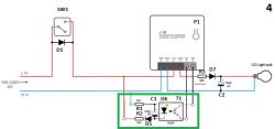
    Section of an electrical schematic with a PC817 optocoupler, 1N4007 diode, 470uF/10V capacitor, and 56K resistors.

    What current will flow through the diode in the optocoupler?
    Won't it be too small?

    Can anyone provide calculations?
  • #64 21406579
    spin55
    Level 17  
    >>21403807

    This is the circuit that was tested and worked: Circuit diagram with electrical components.

    https://www.elektroda.com/rtvforum/topic3971605.html

    In testing I used the components I had on hand at the time. The actual measured values ​​are:

    - R1 and R2 are 45.9K and 46.9K
    - The voltage measured on the pins of capacitor C1 is 1.1 Vdc
    - The current consumed is 1.14 mA
    - The alternating voltage of the mains supply: 236 Vac
    - Peak network voltage: 332 Vac

    The formula to apply is Ohm's law: V = I * R (V being the average DC voltage)
    Vdc = Vp/3.14 (pi)
    Therefore: I = (332/3.14) / (45.9 + 46.9) = 105.73 / 92.8 = 1.14 mA

    https://www.youtube.com/watch?v=sekdEc5wU6k&a...b_ph_WdlLDny2cGloFSxyRgO8B733jeo&index=81

    If we take a look at the optocoupler datasheet, that current of 1.14 mA seems very low compared to the 5 mA or 20 mA that it recommends, but the truth is that it works. To ensure those 5 mA, the resistances would have to be reduced to (18.5K / 2 = 9.3K).

    Greetings

Topic summary

The discussion revolves around modifying the Tuya Mini switch for no-neutral installations, specifically addressing issues related to diode polarity reversal and relay toggling from a wall switch. Users share experiences and suggestions for circuit modifications, including flipping diodes and capacitors to ensure proper operation with the positive half-cycle of AC voltage. Safety measures, such as using fusible resistors, are emphasized. Participants also explore the feasibility of using this setup with ceiling fans and other AC devices, noting the importance of understanding the power requirements and potential risks associated with half-wave DC operation. Successful configurations and troubleshooting steps are shared, along with links to relevant diagrams and videos.
Summary generated by the language model.
ADVERTISEMENT