Teardown the FL-M1 the same as the other Filohome smart switches (FL-M2, FL-M3).
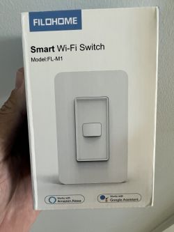
Insert small tool into the slot on the face and pry it open.
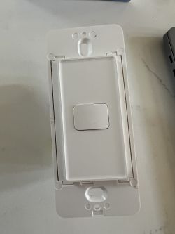
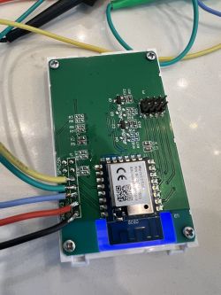
*Note there is a pin header on this model compared to jumper cable on the others.
Pin header on the side of the board
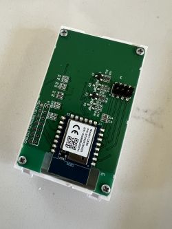
This single switch has the same base board as the other units with provisions for L2 and L3.
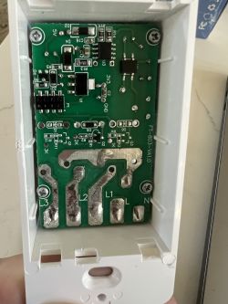
Wire it up and get to flashing
Device configuration, as extracted from Tuya:
- Button (channel 1) on P24
- LED (channel 1) on P10
- WiFi LED on P6
- Relay (channel 1) on P9
Device seems to be using CB3S module, which is using BK7231N.
And the Tuya section starts, as usual, at 2023424

Insert small tool into the slot on the face and pry it open.

*Note there is a pin header on this model compared to jumper cable on the others.
Pin header on the side of the board

This single switch has the same base board as the other units with provisions for L2 and L3.

Wire it up and get to flashing

Code: JSON
Device configuration, as extracted from Tuya:
- Button (channel 1) on P24
- LED (channel 1) on P10
- WiFi LED on P6
- Relay (channel 1) on P9
Device seems to be using CB3S module, which is using BK7231N.
And the Tuya section starts, as usual, at 2023424


