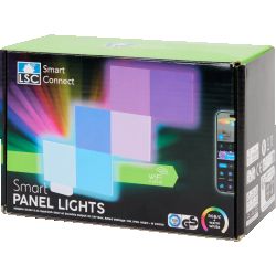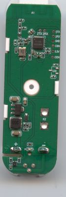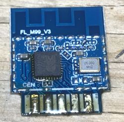
Some of new Tuya IoT devices are based on FL_M99_V1/FL_M99_V2/FL_M99_V3 modules, which are using BK7231N/BL2028N WiFi 2.4GHz + Bluetooth microcontroller. They can be flashed with OpenBeken, which will provide basic Tasmota compatibility and Home Assistant features. Here's a basic FL_M99 pinout and flashing guide.
There have been already multiple reports of similiar modules on our forum, including:
- mini smart switch - Belon BL2028N
- Aubess 2gang Mini Smart Switch BK7231N /CB2S
I have also received recently a WiFi smart switch based on FL_M99_V1, here is this module photo:
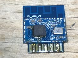
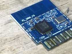
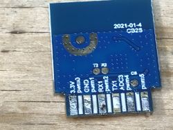
Module pinout seems to match CB2S:
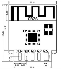
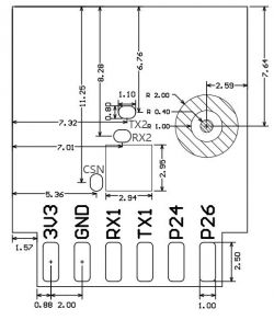
| Pin number | Symbol | I/O type | Function | 1 | 3V3 | P | Power supply 3V3 | 2 | P6 | I/O | Support hardware PWM and correspond to P6 of the IC | 3 | GND | P | Power supply reference ground | 4 | P7 | I/O | Support hardware PWM and correspond to P7 of the IC | 5 | RX1 | I/O | UART_RX1, which is used for receiving user data and corresponds to P10 of the IC. Do not pull it up. By default, the MCU serial port should be in low-level or high-impedance state. | 6 | P8 | I/O | Support hardware PWM and correspond to P8 of the IC | 7 | TX1 | I/O | UART_TX1, which is used for transmitting user data and corresponds to P11 of the IC. Do not pull it up. By default, the MCU serial port should be in low-level or high-impedance state. | 8 | ADC | I/O | ADC, which corresponds to P23 of the IC | 9 | P24 | I/O | Support hardware PWM and correspond to P24 of the IC | 10 | CEN | I/O | Reset pin | 11 | P26 | I/O | Support hardware PWM and correspond to P26 of the IC | Test point | RX2 | I/O | UART_RX2, which corresponds to P1 of the IC. This pin is not allowed to use. | Test point | TX2 | I/O | UART_TX2, which is used for outputting logs and corresponds to P0 of the IC | Test point | CSN | I/O | Mode selection pin. If it is connected to the ground before being powered on, enter the firmware test mode. If it is not connected or connected to VCC before being powered on, enter the firmware application mode. It corresponds to P21 of the IC. |
Availability of 5 PWM outputs makes this module suitable for RGBCW lighting, extra ADC pin can be also used for light sensor.
How to flash FL_M99_V1/FL_M99_V2/FL_M99_V3?
Flash it like CB2S, either in circuit, or desolder it from the board.
You can use our BK7231 flasher for that:
https://github.com/openshwprojects/BK7231GUIFlashTool
You can watch our old (hid_download_py) and new (BK7231tool flasher) guides:
I am usually just desoldering the module, here is my setup:
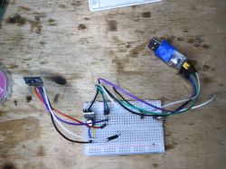
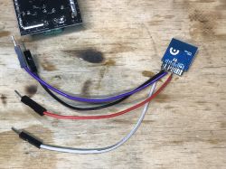
I do not solder CEN, I just do power on/off cycle by disconnecting and reconnecting 3.3V wire.
After flashing, you can refer to one of our many guides for BK7231 setup, including|:
Summary
FL_M99_V1/FL_M99_V2/FL_M99_V3 seems to be flashable just like CB2S. There also seems to be similiar modules, which are CB3S-compatible, for example FL_M93_V1, but I haven't checked it yet.
If you have encountered a device with this or similiar module, please make some photos and let us know. You can also make a teardown post and we'll submit it to our teardowns list
Cool? Ranking DIY Helpful post? Buy me a coffee.


