logo elektroda
logo elektroda
X
logo elektroda

Exploring Advanced Configurations for Atomi Smart Color String Lights with OpenBeken

phobiac 2229 15
ADVERTISEMENT
  • #1 20820312
    phobiac
    Level 4  
    This is more of a call for assistance than a successful setup!

    I have a number of string lights coming from the Atomi Smart brand that were specifically appealing due to being individually addressable. Unfortunately, the Smart Life app does not allow for very much configuration of the lights beyond some poorly made scenes built into it. In digging around to replace that firmware with something more powerful, I've landed on openbeken.

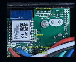
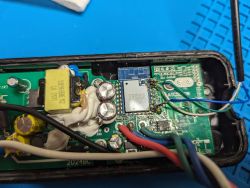
    These lights are a bit odd when it comes to the wifi module. There's a very well written teardown at this blog that is for an older version of these lights using the TYWE3S module based off ESP8266. However, the ones I have (or at least the one I've opened so far) has a CB3S module. See the photos below.

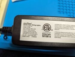
    Close-up of the interior of a lighting module with electronic components and wiring. Label on the power adapter for Atomi Smart string lights with technical information.

    I was able to successfully flash OpenBeken to the device but I'm kind of at a loss for what the next steps are. I've read through this guide but I'm a bit new to this level of hardware hacking and was hoping for some guidance. I did try setting high/low on different pins in the GPIO finder but saw no reaction from my lights.
  • ADVERTISEMENT
  • Helpful post
    #2 20820680
    p.kaczmarek2
    Moderator Smart Home
    Hello, have you tried automatic GPIO extraction?


    Can you attach extracted data here?
    Helpful post? Buy me a coffee.
  • ADVERTISEMENT
  • #3 20824884
    phobiac
    Level 4  

    I've either done something wrong or this is going to be more complicated

    {
    	"baud":"9600",
    	"ap_passwd":"null",
    	"country_code":"null",
    	"bt_mac":"null",
    	"bt_hid":"null",
    	"prod_test":"false",
    	"fac_pin":"ey6nevs5gaj456n0"
    }


    The flashing tool is giving this warning:
    Quote:
    Sorry, no meaningful pins data found. This device may be TuyaMCU or a custom one with no Tuya config data.
    Baud keyword found, this device may be TuyaMCU or BL0942. Baud value is 9600.
    No module information found.
    And the Tuya section starts at UNCOMMON POSITION 0

  • ADVERTISEMENT
  • Helpful post
    #4 20824904
    p.kaczmarek2
    Moderator Smart Home
    This indicates it may be a TuyaMCU device.

    Go to the Web App and in LittleFS tab create autoexec.bat with the following content:
    
    // start TuyaMCU driver
    startDriver TuyaMCU
    // set TuyaMCU default wifi state 0x04, which means "paired",
    // because some TuyaMCU MCUs will not report all data
    // unless they think they are connected to cloud
    tuyaMcu_defWiFiState 4
    

    Then save, then power off totally whole device (pull the plug out), and plug it in again.
    Keep Web App log open.
    Copy here your Web App log so we can see if there are any TuyaMCU packets.

    Then, you can also try to run the following command in the Web App log and watch for reply:
    
    tuyaMcu_sendQueryState


    BTW, I looked into the linked article, it seems they remove U3 which is the MCU of TuyaMCU, but I don't think it's good solution, it would be better to use it:
    Close-up of a circuit board with a TYWE3S module and pin labels, as well as a removed chip U3.
    Do you have original firmware backup (2MB)?
    Helpful post? Buy me a coffee.
  • #5 20825499
    phobiac
    Level 4  
    Unfortunately I can't seem to dump the existing firmware. I've got an unflashed device I just opened up and I get this when trying to

    Quote:
    Going to start reading at offset 0x00...
    Reading 0x00... failed with serial.BytesToRead 4095 (expected 4111)
    The beginning of buffer in UART contains 040EFF01E0FCF4061009000000200069 data.
    Failed! There was no result to save.


    However here's the log after a restart of the device with the autoexec.bat script set up as instructed

    AMCU received: 55 AA 03 00 00 01 01 04 
    Info:TuyaMCU:TuyaMCU_ProcessIncoming[ver=3]: processing command 0 (Hearbeat) with 8 bytes
    Info:MAIN:Time 14, idle 201199/s, free 73448, MQTT 0(0), bWifi 0, secondsWithNoPing -1, socks 2/38 
    Info:MAIN:Time 15, idle 189624/s, free 73448, MQTT 0(0), bWifi 0, secondsWithNoPing -1, socks 2/38 
    Info:MAIN:Time 16, idle 188718/s, free 73448, MQTT 0(0), bWifi 0, secondsWithNoPing -1, socks 2/38 
    Info:MAIN:Time 17, idle 190203/s, free 73448, MQTT 0(0), bWifi 0, secondsWithNoPing -1, socks 2/38 
    Info:TuyaMCU:TUYAMCU received: 55 AA 03 00 00 01 01 04 
    Info:TuyaMCU:TuyaMCU_ProcessIncoming[ver=3]: processing command 0 (Hearbeat) with 8 bytes
    Info:MAIN:Time 18, idle 189802/s, free 73448, MQTT 0(0), bWifi 0, secondsWithNoPing -1, socks 2/38 
    Info:MAIN:Time 19, idle 187656/s, free 73448, MQTT 0(0), bWifi 0, secondsWithNoPing -1, socks 2/38 
    Info:MAIN:Time 20, idle 377773/s, free 73448, MQTT 0(0), bWifi 0, secondsWithNoPing -1, socks 2/38 
    Info:GEN:dhcp=0 ip=0.0.0.0 gate=0.0.0.0 mask=0.0.0.0 mac=10:5a:17:9d:f9:94
    Info:GEN:sta: 0, softap: 0, b/g/n
    Info:MAIN:Main_OnWiFiStatusChange - WIFI_STA_AUTH_FAILED - 3
    Info:MAIN:Time 21, idle 182566/s, free 71056, MQTT 0(0), bWifi 0, secondsWithNoPing -1, socks 2/38 
    Info:TuyaMCU:TUYAMCU received: 55 AA 03 00 00 01 01 04 
    Info:TuyaMCU:TuyaMCU_ProcessIncoming[ver=3]: processing command 0 (Hearbeat) with 8 bytes
    Info:MAIN:Time 22, idle 184355/s, free 70616, MQTT 0(0), bWifi 0, secondsWithNoPing -1, socks 2/38 
    Info:MAIN:Main_OnWiFiStatusChange - WIFI_STA_CONNECTING - 1
    Info:MAIN:Time 23, idle 185826/s, free 71520, MQTT 0(0), bWifi 0, secondsWithNoPing -1, socks 2/38 
    Info:MAIN:Main_OnWiFiStatusChange - WIFI_STA_DISCONNECTED - 2
    Info:MAIN:Time 24, idle 187216/s, free 73440, MQTT 0(0), bWifi 0, secondsWithNoPing -1, socks 2/38 
    Info:MAIN:Time 25, idle 188214/s, free 73440, MQTT 0(0), bWifi 0, secondsWithNoPing -1, socks 2/38 
    Info:TuyaMCU:TUYAMCU received: 55 AA 03 00 00 01 01 04 
    Info:TuyaMCU:TuyaMCU_ProcessIncoming[ver=3]: processing command 0 (Hearbeat) with 8 bytes
    Info:MAIN:Time 26, idle 190633/s, free 73440, MQTT 0(0), bWifi 0, secondsWithNoPing -1, socks 2/38 
    Info:MAIN:Time 27, idle 190000/s, free 73440, MQTT 0(0), bWifi 0, secondsWithNoPing -1, socks 2/38 
    Info:MAIN:Time 28, idle 188415/s, free 73440, MQTT 0(0), bWifi 0, secondsWithNoPing -1, socks 2/38 
    Info:MAIN:Time 29, idle 378538/s, free 73440, MQTT 0(0), bWifi 0, secondsWithNoPing -1, socks 2/38 
    Info:TuyaMCU:TUYAMCU received: 55 AA 03 00 00 01 01 04 
    Info:TuyaMCU:TuyaMCU_ProcessIncoming[ver=3]: processing command 0 (Hearbeat) with 8 bytes
    Info:MAIN:Time 30, idle 189789/s, free 73440, MQTT 0(0), bWifi 0, secondsWithNoPing -1, socks 2/38 
    Info:GEN:dhcp=0 ip=0.0.0.0 gate=0.0.0.0 mask=0.0.0.0 mac=10:5a:17:9d:f9:94
    Info:GEN:sta: 0, softap: 0, b/g/n
    Info:MAIN:Time 31, idle 186953/s, free 73440, MQTT 0(0), bWifi 0, secondsWithNoPing -1, socks 2/38 
    Info:MAIN:Time 32, idle 190055/s, free 73440, MQTT 0(0), bWifi 0, secondsWithNoPing -1, socks 2/38 
    Info:MAIN:Main_OnWiFiStatusChange - WIFI_STA_AUTH_FAILED - 3
    Info:MAIN:Time 33, idle 187232/s, free 73512, MQTT 0(0), bWifi 0, secondsWithNoPing -1, socks 2/38 
    Info:TuyaMCU:TUYAMCU received: 55 AA 03 00 00 01 01 04 
    Info:TuyaMCU:TuyaMCU_ProcessIncoming[ver=3]: processing command 0 (Hearbeat) with 8 bytes
    Info:MAIN:Time 34, idle 187475/s, free 70712, MQTT 0(0), bWifi 0, secondsWithNoPing -1, socks 2/38 
    Info:MAIN:Time 35, idle 187413/s, free 70712, MQTT 0(0), bWifi 0, secondsWithNoPing -1, socks 2/38 
    Info:MAIN:Main_OnWiFiStatusChange - WIFI_STA_CONNECTING - 1
    Info:MAIN:Main_OnWiFiStatusChange - WIFI_STA_CONNECTED - 4
    Info:MAIN:Main_OnWiFiStatusChange - WIFI_STA_CONNECTED - 4
    Info:MAIN:Time 36, idle 170540/s, free 73280, MQTT 0(0), bWifi 1, secondsWithNoPing -1, socks 2/38 
    Info:MAIN:Time 37, idle 194262/s, free 73320, MQTT 0(0), bWifi 1, secondsWithNoPing -1, socks 2/38 
    Info:TuyaMCU:TUYAMCU received: 55 AA 03 00 00 01 01 04 
    Info:TuyaMCU:TuyaMCU_ProcessIncoming[ver=3]: processing command 0 (Hearbeat) with 8 bytes
    Info:MQTT:mqtt_host empty, not starting mqtt
    Info:MAIN:Time 38, idle 192621/s, free 73320, MQTT 0(1), bWifi 1, secondsWithNoPing -1, socks 2/38 
    Info:MAIN:Time 39, idle 190891/s, free 73320, MQTT 0(1), bWifi 1, secondsWithNoPing -1, socks 2/38 
    Info:MAIN:Time 40, idle 189853/s, free 73320, MQTT 0(1), bWifi 1, secondsWithNoPing -1, socks 2/38 
    Info:GEN:dhcp=0 ip=REDACTED gate=REDACTED mask=255.255.252.0 mac=10:5a:17:9d:f9:94
    Info:GEN:sta: 1, softap: 0, b/g/n
    Info:GEN:sta:rssi=-51,ssid=REDACTED,bssid=REDACTED,channel=2,cipher_type:CCMP
    Info:MAIN:Time 41, idle 206394/s, free 73320, MQTT 0(1), bWifi 1, secondsWithNoPing -1, socks 2/38 
    Info:TuyaMCU:TUYAMCU received: 55 AA 03 00 00 01 01 04

    It then gets a bit repetitive. If I'm reading that right it's connecting to my wireless network as expected.

    Here's the output from running the tuyaMcu_sendQueryState command

    Info:CMD:[WebApp Cmd 'tuyaMcu_sendQueryState' Result] OK
    Info:TuyaMCU:TUYAMCU received: 55 AA 03 07 00 05 01 01 00 01 01 12 
    Info:TuyaMCU:TuyaMCU_ProcessIncoming[ver=3]: processing command 7 (State) with 12 bytes
    Info:TuyaMCU:TuyaMCU_ParseStateMessage: processing dpId 1, dataType 1-DP_TYPE_BOOL and 1 data bytes
    Info:TuyaMCU:TuyaMCU_ParseStateMessage: raw data 1 byte: 1
    Info:TuyaMCU:TUYAMCU received: 55 AA 03 07 00 05 02 04 00 01 0A 1F 
    Info:TuyaMCU:TuyaMCU_ProcessIncoming[ver=3]: processing command 7 (State) with 12 bytes
    Info:TuyaMCU:TuyaMCU_ParseStateMessage: processing dpId 2, dataType 4-DP_TYPE_ENUM and 1 data bytes
    Info:TuyaMCU:TuyaMCU_ParseStateMessage: raw data 1 byte: 10
    Info:TuyaMCU:TUYAMCU received: 55 AA 03 07 00 08 03 02 00 04 00 00 00 FF 19 
    Info:TuyaMCU:TuyaMCU_ProcessIncoming[ver=3]: processing command 7 (State) with 15 bytes
    Info:TuyaMCU:TuyaMCU_ParseStateMessage: processing dpId 3, dataType 2-DP_TYPE_VALUE and 4 data bytes
    Info:TuyaMCU:TuyaMCU_ParseStateMessage: raw data 4 int: 255
    Info:TuyaMCU:TUYAMCU received: 55 AA 03 07 00 08 04 02 00 04 00 00 00 00 1B 
    Info:TuyaMCU:TuyaMCU_ProcessIncoming[ver=3]: processing command 7 (State) with 15 bytes
    Info:TuyaMCU:TuyaMCU_ParseStateMessage: processing dpId 4, dataType 2-DP_TYPE_VALUE and 4 data bytes
    Info:TuyaMCU:TuyaMCU_ParseStateMessage: raw data 4 int: 0
    Info:TuyaMCU:TUYAMCU received: 55 AA 03 07 00 12 05 03 00 0E 66 66 30 30 30 30 30 30 30 30 66 66 66 66 15 
    Info:TuyaMCU:TuyaMCU_ProcessIncoming[ver=3]: processing command 7 (State) with 25 bytes
    Info:TuyaMCU:TuyaMCU_ParseStateMessage: processing dpId 5, dataType 3-DP_TYPE_STRING and 14 data bytes
    Info:TuyaMCU:TUYAMCU received: 55 AA 03 07 00 18 65 03 00 14 66 66 66 66 30 35 30 32 66 66 30 30 30 30 66 66 66 66 30 30 80 
    Info:TuyaMCU:TuyaMCU_ProcessIncoming[ver=3]: processing command 7 (State) with 31 bytes
    Info:TuyaMCU:TuyaMCU_ParseStateMessage: processing dpId 101, dataType 3-DP_TYPE_STRING and 20 data bytes


    The lights have a power button that also cycles through a few pre-set scenes. Here's some logs captured while pressing that button a few times.

    nfo:TuyaMCU:TuyaMCU_ProcessIncoming[ver=3]: processing command 7 (State) with 12 bytes
    Info:TuyaMCU:TuyaMCU_ParseStateMessage: processing dpId 2, dataType 4-DP_TYPE_ENUM and 1 data bytes
    Info:TuyaMCU:TuyaMCU_ParseStateMessage: raw data 1 byte: 5
    
    Info:TuyaMCU:TuyaMCU_ProcessIncoming[ver=3]: processing command 7 (State) with 12 bytes
    Info:TuyaMCU:TuyaMCU_ParseStateMessage: processing dpId 2, dataType 4-DP_TYPE_ENUM and 1 data bytes
    Info:TuyaMCU:TuyaMCU_ParseStateMessage: raw data 1 byte: 6
    
    Info:TuyaMCU:TuyaMCU_ProcessIncoming[ver=3]: processing command 7 (State) with 12 bytes
    Info:TuyaMCU:TuyaMCU_ParseStateMessage: processing dpId 2, dataType 4-DP_TY f and 1 data bytes
    Info:TuyaMCU:TuyaMCU_ParseStateMessage: raw data 1 byte: 7


    The raw data 1 byte value seems to range from 0-10
  • #6 20825510
    p.kaczmarek2
    Moderator Smart Home
    phobiac wrote:
    Unfortunately I can't seem to dump the existing firmware. I've got an unflashed device I just opened up and I get this when trying to

    Quote:
    Going to start reading at offset 0x00...
    Reading 0x00... failed with serial.BytesToRead 4095 (expected 4111)
    The beginning of buffer in UART contains 040EFF01E0FCF4061009000000200069 data.
    Failed! There was no result to save.

    This is TuyaMCU device. Flashing may fail because the same port which we use for flashing is used for communication with TuyaMCU. Maybe you need to cut the connection first.
    You can also try old Python flasher - hid_download_py, see: https://www.youtube.com/watch?v=PKkiqDNFIx8

    These TuyaMCU data looks good, we need to look deeper into that, figure out what each dpID means and then you can send it from OBK to control the LED strip.
    Helpful post? Buy me a coffee.
  • #7 20825577
    phobiac
    Level 4  
    hid_download.py allowed me to dump the firmware from the string of lights I have that hasn't been flashed, I've attached it here but can also run my own analysis if there's information on how you have to link me to.

    I've been trying to parse the dpID but I'm pretty unfamiliar with this process. Randomly changing things in the GPIO Doctor wasn't getting me very far. Is there a way for me to replicate sending the data that was logged when the power/scene button is pressed and modify bits of it to see what changes? The schematic for the CB3S chip is here if that helps narrow anything down.

    Greatly appreciate your guidance so far!
  • Helpful post
    #8 20826031
    p.kaczmarek2
    Moderator Smart Home
    phobiac wrote:
    hid_download.py allowed me to dump the firmware from the string of lights I have that hasn't been flashed, I've attached it here but can also run my own analysis if there's information on how you have to link me to.

    In this case it won't help futher.
    You can get dpID meanings if you follow this guide (more or less, I haven't tried it myself):
    https://www.zigbee2mqtt.io/advanced/support-new-devices/03_find_tuya_data_points.html


    phobiac wrote:

    Randomly changing things in the GPIO Doctor wasn't getting me very far.

    GPIO is not used when TuyaMCU is active, so it won't help. All data goes through UART.


    phobiac wrote:
    Is there a way for me to replicate sending the data that was logged when the power/scene button is pressed and modify bits of it to see what changes?

    I would suggest making first UART capture with out analyzer https://github.com/openshwprojects/TuyaMCUAnalyzer and observing what operation in Tuya app causes which packets to be send on original tuya firmware, but in obk, you can also manually send states with:
    
    tuyaMcu_sendState	[dpID] [dpType] [dpValue]
    

    Table with tuyaMcu_sendState command in documentation.
    https://github.com/openshwprojects/OpenBK7231T_App/blob/main/docs/commands.md

    For example, you can use it to send dpID 1, bool, which may be power on or off:
    
    Info:TuyaMCU:TuyaMCU_ProcessIncoming[ver=3]: processing command 7 (State) with 12 bytes
    Info:TuyaMCU:TuyaMCU_ParseStateMessage: processing dpId 1, dataType 1-DP_TYPE_BOOL and 1 data bytes
    Info:TuyaMCU:TuyaMCU_ParseStateMessage: raw data 1 byte: 1


    Later, you can just remap dpID to a channel in OBK, to get a WWW panel button. Add the following to your autoexec.bat script:
    
    setChannelType 1 toggle
    // linkTuyaMCUOutputToChannel dpId verType tgChannel
    linkTuyaMCUOutputToChannel 1 bool 1
    

    The following should set channel 1 of OBK to toggle, and then map it as a boolean to dpID 1. Then you will get a button on WWW panel of OBK. When you toggle this button, this will automatically send setting of dpID 1 (boolean) to either 1 or 0 to TuyaMCU. This will also receive changes from TuyaMCU (for example, if your device has a physical button that is connected to MCU).
    Read more at: https://github.com/openshwprojects/OpenBK7231T_App/blob/main/docs/autoexecExamples.md
    Helpful post? Buy me a coffee.
  • #9 20826813
    phobiac
    Level 4  
    Okay, I'm playing around with the tuyaMcu_sendState command and it seems like I can toggle through the various pre-programmed scenes just fine. I'm going to mess around with that more and document what I find.

    For TuyaMCU Analyzer, I must be doing something wrong. I think I'm misunderstanding how to use it. Should I be hooking my serial-to-usb converter up to the unflashed device, or the one with OpenBeken flashed to it? Additionally, should I be soldering on to the same RX/TX pin pair I'd use for flashing or should this be connected directly to the TM1814 chip, which is the MCU chip?
  • #10 20826835
    p.kaczmarek2
    Moderator Smart Home
    phobiac wrote:
    Okay, I'm playing around with the tuyaMcu_sendState command and it seems like I can toggle through the various pre-programmed scenes just fine. I'm going to mess around with that more and document what I find.

    We are also working on "direct" LED driver so in future you can skip the MCU chip, but it's not ready yet.

    phobiac wrote:

    For TuyaMCU Analyzer, I must be doing something wrong. I think I'm misunderstanding how to use it. Should I be hooking my serial-to-usb converter up to the unflashed device, or the one with OpenBeken flashed to it? Additionally, should I be soldering on to the same RX/TX pin pair I'd use for flashing or should this be connected directly to the TM1814 chip that's you said is the MCU chip?

    The TuyaMCU analyzer is of course used to capture the communication with original Tuya firmware, so we can replicate it in OBK later. You do the capture separately on both lines, first RX(WiFI)->TX(MCU) and then TX(WiFI)->RX(MCU). The capture should be done while doing operations in Tuya app and you should note down each operation you do, so you can tell what happens when you, for example, turn on the light, or change brightness to 50%, or set color to green....
    Helpful post? Buy me a coffee.
  • #11 20827184
    phobiac
    Level 4  
    Huge progress!

    Here's my current autoexec.bat
    
    // start TuyaMCU driver
    startDriver TuyaMCU
    // set TuyaMCU default wifi state 0x04, which means "paired",
    // because some TuyaMCU MCUs will not report all data
    // unless they think they are connected to cloud
    tuyaMcu_defWiFiState 4
    
    // setChannelType 2 toggle
    // linkTuyaMCUOutputToChannel dpId verType tgChannel
    
    // On/Off
    setChannelType 1 toggle
    linkTuyaMCUOutputToChannel 1 bool 1
    
    // Set scene/mode, ranges from 2-10 with 9 (the pick 2 scene) being a special case that uses dpId 101 to set the 2 colors
    setChannelType 2 
    linkTuyaMCUOutputToChannel 2 enum 2
    
    // Set brightness for white mode
    setChannelType 3 dimmer256
    linkTuyaMCUOutputToChannel 3 val 3
    
    // Set color temp for white mode, ranges from 1 - 255
    setChannelType 4 textfield
    linkTuyaMCUOutputToChannel 4 val 4
    
    // Set color
    // Uses a string that sets RGBW color, brightness, and saturation
    // Red only	brightness 100	Saturation 100: 	ff00000000ffff
    // Green only	brightness 100	Saturation 100: 	00ff000000ffff
    // Blue only	brightness 100	Saturation 100: 	0000ff0000ffff
    // White only 	DOES NOT WORK, USE dpId 3		000000ff00ffff
    // White all 	brightness 100	Saturation 100:		ffffff0000ffff
    // 
    // ex.) tuyaMcu_sendState 5 3-DP_TYPE_STRING ff00000000ffff
    setChannelType 5 textfield
    linkTuyaMCUOutputToChannel 5 string 5
    
    // Set colors for pick 2
    setChannelType 6 textfield
    linkTuyaMCUOutputToChannel 101 string 6


    It has a few problems that are more me being unfamiliar with the tools. For one, I can't figure how to correctly set color temperature when in white mode or set things for the manual color picker. Running a command directly with the relevant string works, but in the WWW interface TextField seems to be only accepting numeric values for some reason. For the scene/mode selector, I can't figure how to limit the range.

    Here's a general breakdown of what I learned for this device.

    There are 6 dpIds as pulled from the Tuya developer website
    1 - Switch - On/Off, boolean
    2 - Mode - Scene switch, value, ranges from 0-10 with scene 9 also using dpId 101
    3 - Brightness - White mode bulb brightness, value, ranges from 5-255
    4 - White Temperature - White mode color temp, value, ranges from 1-255
    5 - Color Data - Manually set color, string, uses a 14 character string to set color, saturation, and brightness
    101 - 颜色 (Translates to color) - Manually set 2 colors for scene 9, string, uses a 19 character string to set 2 colors, saturation, and brightness

    The numeric values for scenes from dpId 2 are:
    0 - Not marked in app, appears to just be last used white mode settings
    1 - Not marked in app, appears to just be last used color mode settings
    2 - Strobe - Cycles through colors, no transition
    3 - Fade - Cycles through colors, fading transition between them
    4 - Pulse - Cycles through colors, turning off bulb before going to next color
    5 - Blink - Pulse but faster
    6 - Chase - Cycles through colors, lighting one bulb at a time to give a chase effect
    7 - Christmas - Red/Green alternating
    8 - America - Red/White/Blue alternating
    9 - Pick 2 - Uses the value from dpId 101 to do 2 alternating colors
    10 - Multi - Rainbow down the length of the light strip, static with bulbs from from red to purple

    I have not 100% figured out the string formats for dpId 5 and 101 but have some ideas.

    For dpId 5, the 14 character string, the format appears to be Red Green Blue White brighTness? Saturation? or RGBWTS, but I'm not certain of the brightness and saturation. A few examples that are very straightforward, pulled from the autoexec.bat comments
    Red only brightness 100 Saturation 100: ff00000000ffff
    Green only brightness 100 Saturation 100: 00ff000000ffff
    Blue only brightness 100 Saturation 100: 0000ff0000ffff

    Some more complex examples, complicated by me setting these from the in app color picker
    Set with brightness 50, saturation 50
    Red: 8a464600007d8a
    Set with brightness 100, saturation 0
    Red: ffffff000000ff
    Set with brightness 1, saturation 100
    Red: 1a00000000ff19

    For dpId 101, the 19 character string is clearly following a similar encoding
    Set with brightness 100, saturation 100
    Red 1, Yellow 2: fff0502ff0000ffff00
    Red 1, Blue 2: ffff0502ff0000090ff
  • #12 20827348
    p.kaczmarek2
    Moderator Smart Home
    Good job, I will help you integrate it with OBK. According to xdrv comment:
    
          // There are two types of rgb format, configure the correct one using TuyaRGB command.
          // The most common is 0HUE0SAT0BRI0 and the less common is RRGGBBFFFF6464 and sometimes both are case sensitive:
          // 0  type 1 Uppercase - 00DF00DC0244
          // 1  Type 1 Lowercase - 008003e8037a
          // 2  Type 2 Uppercase - 00FF00FFFF6464
          // 3  Type 2 Lowercase - 00e420ffff6464
    

    Your color format seems to be type 3, however, it seems that Tasmota guys are not aware about the fact that it can also encode brightness, and they think that last 4 characters are always 6464.

    The RGB part matches RRGGBBFFFF6464 .

    Quote:

    Set with brightness 50, saturation 50
    Red: 8a464600007d8a

    This may be problematic. If we know that first chars are RR, GG, and BB, then what is the meaning of the latter? Can you investigate? Maybe try to slowly change brightness from 100% to 0%? And then saturation?

    I can make it work with our OBK but I need to know what is the meaning of the remaining bytes.
    Helpful post? Buy me a coffee.
  • ADVERTISEMENT
  • #13 20839431
    phobiac
    Level 4  
    Apologies for the wait! Holiday ate up my time. Here's some more data to try to parse out what's happening. The colors are a little difficult to set since the color wheel given in the Smartlife app doesn't give a way to set a color based on hex code or anything more precise. However, I did set the same choice from the saved colors for these Red, Green, and Blue tables so the Hue should (in theory) be the same for both.

    Color (Brightness 100)Saturation 100Saturation 99Saturation 50 Saturation 0
    Redff00000000ffffff03030000fcffff808000007fffffffff000000ff
    Green00ff1e007fffff03ff20007ffcff80ff8e007f80ffffffff007f00ff
    Blue0000ff00f0ffff0303ff00f0fdff8080ff00f07fffffffff00f000ff


    Color (Saturation 100)Brightness 100Brightness 99Brightness 50 Brightness 1
    Redff00000000fffffc00000000fffc8c00000000ff8b1a00000000ff19
    Green00ff1e007fffff00fc1d007ffffc008c10007fff8b001a03007fff19
    Blue0000ff00f0ffff0000fc00f0fffc00008c00f0ff8b00001a00f0ff19


    Since Red is most reliably actually red, and setting saturation to 0 seems to result in white light, I also grabbed these values. The Red line might be the most useful but I did it for the other colors too.

    Color (Saturation 0)Brightness 100Brightness 99Brightness 50 Brightness 1
    Redffffff000000fffcfcfc000000fc8c8c8c0000008b1a1a1a00000019
    Greenffffff007f00fffcfcfc007f00fc8c8c8c007f008b1a1a1a007f0019
    Blueffffff00f000fffcfcfc00f000fc8c8c8c00f0008b1a1a1a00f00019


    Given this it looks like the format used is something like where T is brightness and S is saturation? Not entirely sure since the Saturation also seems to change the RGB values.
    RRGGBB00SSSSTT

    It's interesting that the middle two seem to not be used. I'm not sure if this is relevant here, but from my digging into the hardware of these lights I learned each individual bulb processes and then passes along the command for what color/scene to set. It is possible the two middle bits are for bulb counting?
  • #14 21060630
    mchipser
    Level 3  

    just checking in to see if you made any progress on this? I have a few of these and would like to get it configured..
  • #15 21060978
    p.kaczmarek2
    Moderator Smart Home
    Hello, it have been some time ago and I don't remember exactly where we've stopped, but have you seen the tuyaMcu_setupLED command?
    Table with tuyaMcu_setupLED command for TuyaMCU.
    Here is more info:
    https://www.elektroda.com/rtvforum/find.php?q=tuyaMcu_setupLED
    Here is our commands list:
    https://github.com/openshwprojects/OpenBK7231T_App/blob/main/docs/commands.md
    Here are autoexec.bat samples:
    https://github.com/openshwprojects/OpenBK7231T_App/blob/main/docs/autoexecExamples.md
    Maybe we can try to use tuyaMcu_setupLED for your device or at least try to alter it to support your case?
    Helpful post? Buy me a coffee.
  • #16 21445488
    phobiac
    Level 4  
    Hello! It's been a while since I had the time to come back to this project. I've had a little success using OpenBeken on some simpler devices and I have more confidence now in trying to get these lights working. As things stand, my personal testing with these lights has found the TuyaMCU chip to be severely lacking in options for controlling the lights. I have given up personally on exploring that anymore as what I want is full control over the individual LEDs and the TuyaMCU at best allows setting 2 alternating colors.

    I have one string of lights that I have wired up as described in the teardown linked from my first post but I am trying to use the existing CB3S module flashed with OpenBeken instead of replacing it with an ESP32. I was hoping you could assist with instruction on what my next step should be in trying this out. The setup is:

    CBS3 chip flashed with OpenBK

    I have removed the TuyaMCU chip entirely from the board to prevent it from conflicting

    A voltage shifter has been wired up between the CBS3 which outputs 3.3v and the 5v the LED lights are expecting (I understand this was previously done by the MCU chip)

    Pin 7/GPIOP_6/PWM0 is wired to the D0 wire through the voltage shifter

    The LED string should be GRBW

    I understand that with this setup I should be sending serial commands to the LED string through GPIO 6. What I'm not sure of is how to configure OpenBK to do so. The individual LEDs use TM1814 chips. The teardown post links to a WLED github issue that explains some of the particulars of this chip. I'm not sure if OpenBK already knows how to communicate with it.

    If this does work then it's slightly more effort than simply flashing the device, but ultimately it's just remove the MCU chip and wiring in the voltage shifter.

Topic summary

The discussion revolves around configuring Atomi Smart Color String Lights using OpenBeken firmware due to limitations in the Smart Life app. The user successfully flashed OpenBeken onto their lights, which utilize a CB3S Wi-Fi module, and seeks assistance in further configuration. Responses include suggestions for automatic GPIO extraction, using TuyaMCU commands, and capturing UART communication to replicate original firmware functionality. The user has made progress in controlling the lights through TuyaMCU commands and is working on parsing data points for color and brightness settings. Additional resources and commands for further integration with OpenBeken are provided.
Summary generated by the language model.
ADVERTISEMENT