
logo elektroda
logo elektroda
X
logo elektroda

VTA+ Ray II Smart Relay Module: Rebranded RSH-SB03-WiFi, BK7231N Teardown and Flashing

jskvbinmv 2073 1

TL;DR

  • VTA+ Ray II Smart Relay Module (Model No. VTA-84576) from Homecenter Colombia turned out to be a rebranded RSH-SB03-WiFi board.
  • Inside, the CB3S chip uses a BK7231N platform, and the module opens easily by removing the bottom plate with a flat screwdriver.
  • The PCB exposes 3.3V, Ground, CEN, TX, and RX, and the module was flashed with BK7231Flasher by briefly pulling CEN to ground.
  • Flashing succeeded with OpenBeken after discovering the CB3S chip is not compatible with Tasmota.
  • The button was changed to a toggle for use under a rocker switch, and the original firmware was backed up.
AI summary based on the discussion. May contain errors.
ADVERTISEMENT
📢 Listen (AI voice):

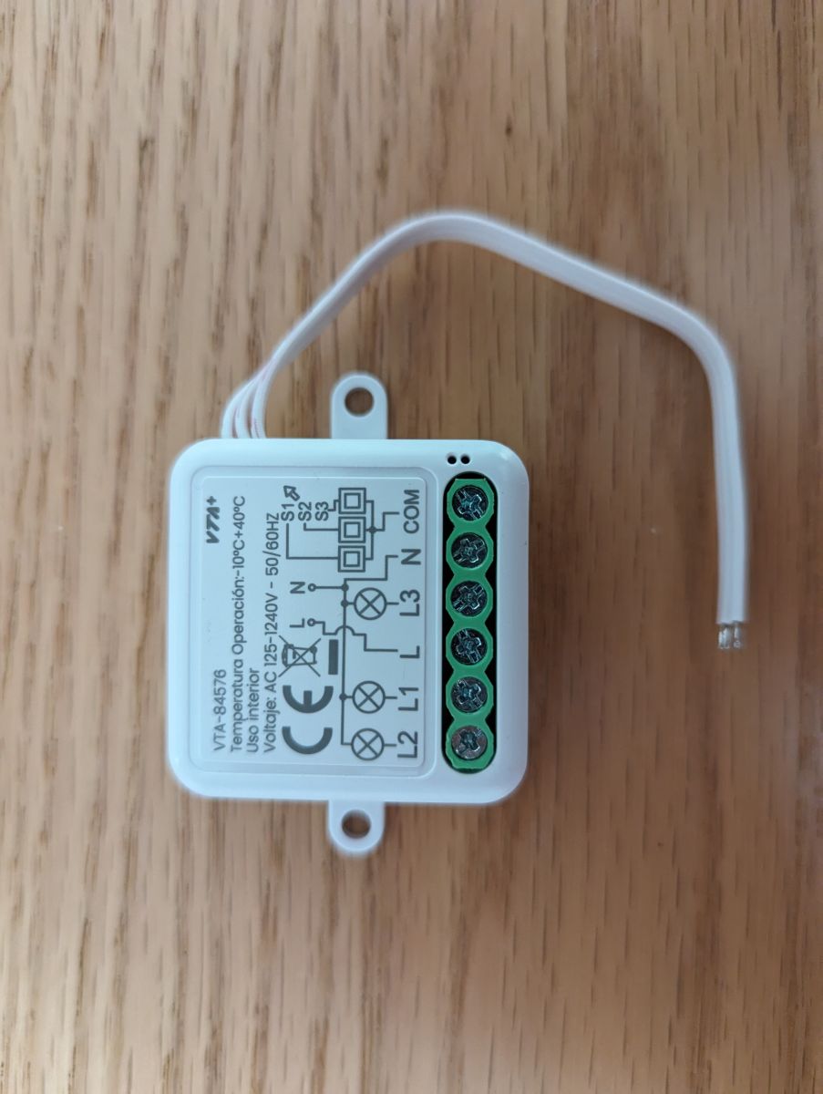
  • I found this Smart Relay Module at Homecenter in Colombia but couldn't find any information about the brand or the module online. After opening it up, I found a model number on the PCB and it seems to be a rebranded version of an RSH-SB03-WiFi Module. Here in Colombia, it is branded VTA+ Ray II (Model No. VTA-84576).
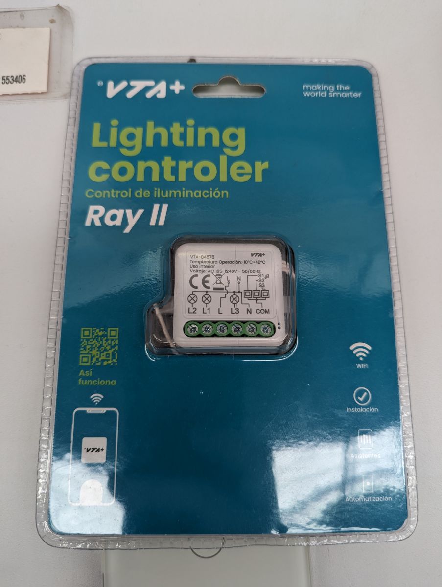
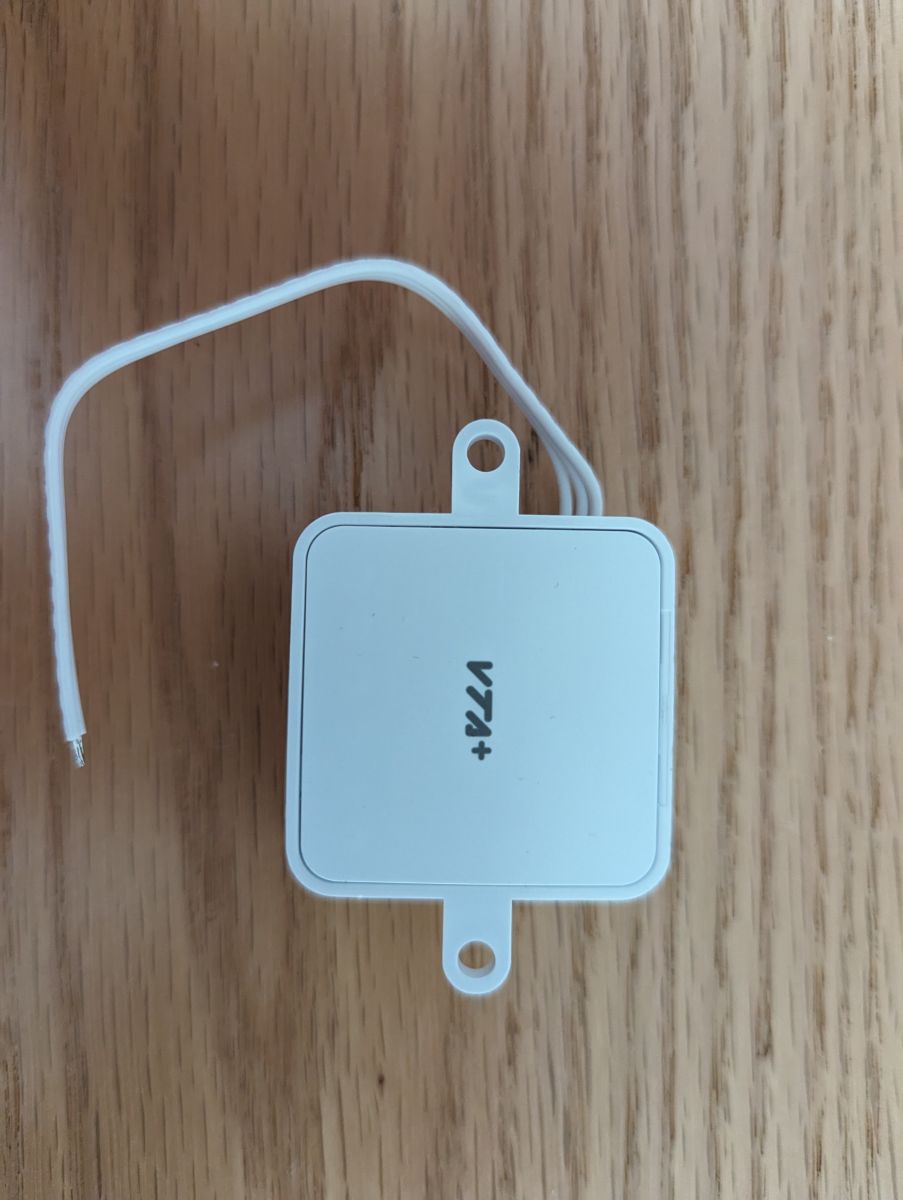
    VTA+ Ray II relay module in packaging
    White relay module with VTA+ text on a wooden surface. Image of the VTA+ Ray II WiFi module with visible terminals and markings.

    The device is easy to open by removing the bottom plate with a flat screwdriver and then pushing on the connectors and the cables to get the module out of its case. No glue anywhere.
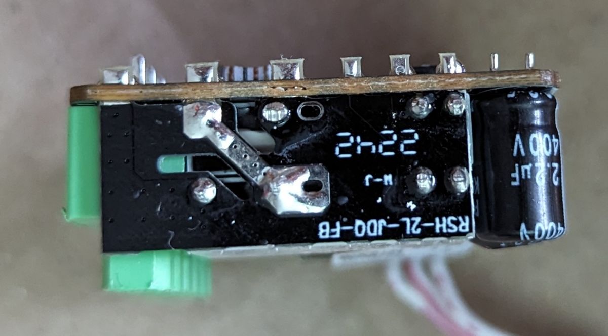
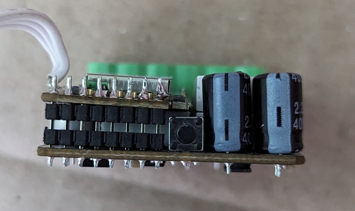
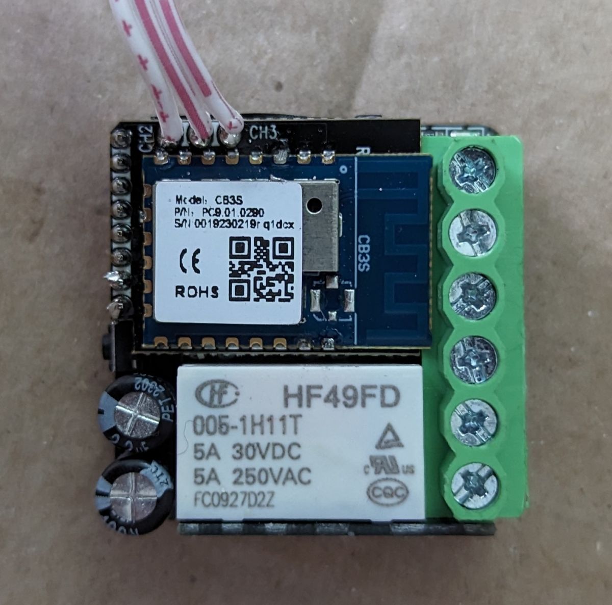
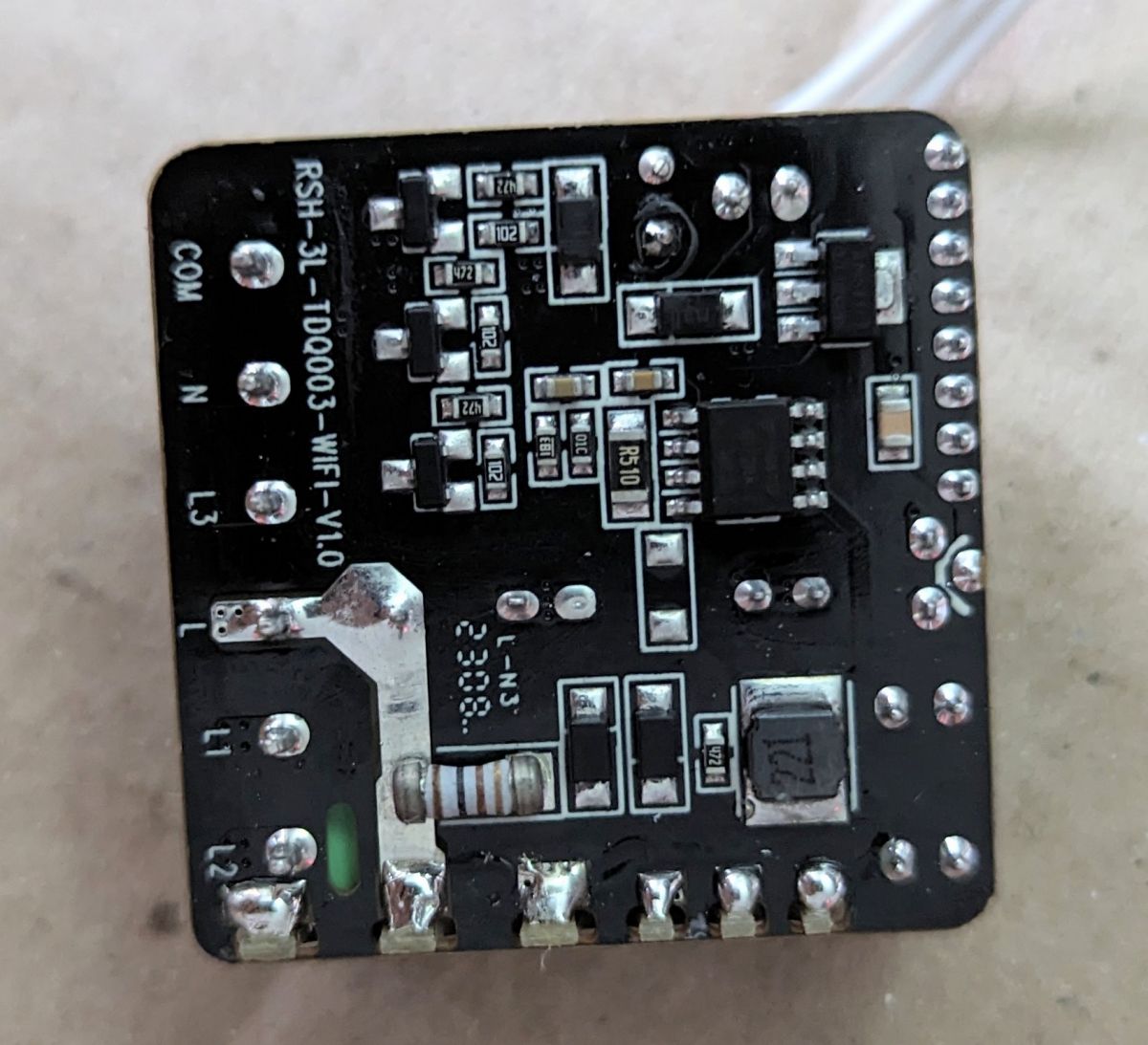
    Relay module with visible circuit board and capacitor. Close-up of a smart relay module showing electronic components, including capacitors and buttons. Relay module with CB3S chip and HF49FD marking. Close-up of RSH-3L-TD0003-WIFI-V1.0 module showing electronic components on the circuit board.

    This was my first time opening up a module without already existing documentation, and I found out the CB3S Chip is not compatible with Tasmota. That's how I stumbled on OpenBeken.

    The Datasheet of the CB3S Chip shows the Pinout (inverted/Bottom view).
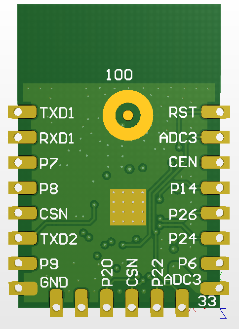
    Bottom view of the CB3S module with pin labels.

    3.3V and Ground are connected to the two right pins, and it is relatively easy to solder a wire to those two. CEN, TX, and RX don't seem to be connected to anything (but I am a noob with those things), but it was not too difficult either to add a little blob of solder and connect a wire.
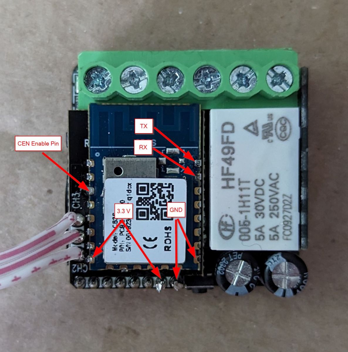
    Inside view of a relay module with labeled pins

    I then successfully flashed BK7231N using the BK7231Flasher. (Tapped the wire connected to CEN briefly to ground when asked to)

    My configuration looks like this. I changed the Button to a toggle because I am using it under a rocker switch:
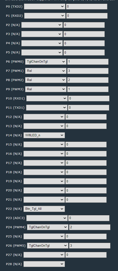
    Screenshot of WiFi relay module configuration interface

    This is my first time posting here. So if I missed any vital information, let me know. I also have a backup of the original firmware, I believe...

    Cool? Ranking DIY
    About Author
    jskvbinmv
    Level 1  
    Offline 
    jskvbinmv wrote 1 posts with rating 1. Been with us since 2023 year.
  • ADVERTISEMENT
  • #2 20873274
    p.kaczmarek2
    Moderator Smart Home
    Posts: 14717
    Help: 659
    Rate: 12794
    Thank you, can you attach device Tuya JSON, like in our tutorial:


    And/or OBK template from the web app?
    Helpful post? Buy me a coffee.
📢 Listen (AI voice):

FAQ

TL;DR: For owners of the VTA+ Ray II relay who need local flashing, this teardown exposes 5 flash pads and confirms: "CB3S is not compatible with Tasmota." The module matches an RSH-SB03-WiFi-style design, opens without glue, and was flashed successfully with BK7231Flasher by briefly grounding CEN during the process. [#20873027]

Why it matters: This FAQ gives relay modders a repeatable path from unknown retail hardware to a working OpenBeken setup with verified board-level details.

Option Chip/module path discussed Compatibility result Flashing status in thread
Tasmota CB3S / BK7231N device Not compatible Not used successfully
OpenBeken CB3S / BK7231N device Used instead Flashed successfully

Key insight: The practical breakthrough was not brand research but PCB identification: once the poster recognized the CB3S/BK7231N platform, OpenBeken became the workable path and the relay flashed successfully with simple wire access and a brief CEN-to-ground action. [#20873027]

Quick Facts

  • The board was sold in Colombia as VTA+ Ray II, model VTA-84576, but the PCB markings pointed to a rebranded RSH-SB03-WiFi design. [#20873027]
  • The module opens by removing the bottom plate with a flat screwdriver; the poster reported no glue anywhere, which lowers case-damage risk during teardown. [#20873027]
  • Flash access used 3.3 V, GND, TX, RX, and CEN on the CB3S area; the two right pins carried 3.3 V and ground. [#20873027]
  • The poster successfully flashed a BK7231N device with BK7231Flasher and briefly tapped the CEN wire to ground when prompted. [#20873027]
  • After flashing, the OpenBeken setup changed the button mode to toggle because the relay was installed under a rocker switch. [#20873027]

How can I identify whether the VTA+ Ray II smart relay module is a rebranded RSH-SB03-WiFi device?

Open the case and check the PCB markings. The poster bought the unit in Colombia as VTA+ Ray II, model VTA-84576, then found a board model that matched an RSH-SB03-WiFi-style module. That board-level identifier was the clearest evidence that the retail branding was a rebrand rather than a unique hardware design. [#20873027]

What is the CB3S chip, and how is it related to the BK7231N used in smart relay modules?

"CB3S is a Wi-Fi module that hosts the BK7231N, providing the relay’s wireless control hardware in a compact board format." In this thread, the poster identified a CB3S module on the relay and then flashed the BK7231N on that module using BK7231Flasher. The CB3S datasheet also provided the pinout view used for wiring. [#20873027]

Why is the CB3S module not compatible with Tasmota, and why do people use OpenBeken instead?

The poster found that this CB3S-based device was not compatible with Tasmota, so they switched to OpenBeken instead. That change solved the flashing problem on this BK7231N relay and led to a successful installation. In this thread, OpenBeken is the working option and Tasmota is the rejected one. [#20873027]

How do I safely open the VTA+ Ray II smart relay module without damaging the case or PCB?

Remove the bottom plate with a flat screwdriver, then push on the connectors and cables to slide the module out. The poster reported no glue anywhere, so the case separated mechanically rather than adhesively. That makes this teardown easier than glued smart modules, but you still need controlled pressure to avoid cracking the PCB or terminal block. [#20873027]

Which pins on the CB3S module are used for 3.3V, GND, TX, RX, and CEN when flashing OpenBeken?

The thread identifies five useful flash connections: 3.3V, GND, TX, RX, and CEN. The two right pins carried 3.3V and ground, and the poster soldered wires to those first. They then added solder blobs to access CEN, TX, and RX, using the CB3S datasheet’s inverted bottom-view pinout as the guide. [#20873027]

What is CEN on a BK7231N or CB3S module, and why do I need to briefly connect it to ground during flashing?

CEN is the control line the poster used to trigger the flash process at the right moment. In practice, they briefly tapped the CEN wire to ground when BK7231Flasher asked for it, and that enabled a successful flash on the BK7231N relay. The thread presents that short ground action as a required step, not an optional tweak. [#20873027]

How do I flash a BK7231N-based VTA+ Ray II relay using BK7231Flasher step by step?

Use this 3-step process. 1. Open the relay, identify the CB3S area, and solder wires to 3.3V, GND, TX, RX, and CEN. 2. Use the CB3S datasheet pinout and connect the relay to BK7231Flasher. 3. When the flasher prompts you, briefly tap the CEN wire to ground to start flashing. The poster completed these steps successfully on a BK7231N-based unit. [#20873027]

What should I do if the TX, RX, or CEN pads on the CB3S do not seem to be connected to anything visible on the board?

Solder directly to the CB3S module pads even if those lines do not appear routed to obvious board points. The poster wrote that CEN, TX, and RX did not seem connected to anything visible, but adding a small solder blob still made wire attachment possible. That edge case matters because missing test pads do not prevent flashing on this board. [#20873027]

How do I configure OpenBeken for the VTA+ Ray II or RSH-SB03-WiFi relay after flashing it?

Apply the relay configuration in OpenBeken and then adjust the button behavior to match your wall switch. The poster shared a working configuration screenshot and changed the button from momentary behavior to toggle because the relay sat under a rocker switch. That post confirms both successful flashing and successful post-flash configuration. [#20873027]

Why would I change the OpenBeken button setting from momentary to toggle when using a rocker switch?

Use toggle so the software input matches the physical two-position behavior of a rocker switch. The poster made exactly that change after flashing OpenBeken, because a rocker switch does not behave like a momentary pushbutton. That setting improves state consistency between the wall control and the relay logic. [#20873027]

OpenBeken vs Tasmota for BK7231N smart relays: which is better and what are the compatibility differences?

In this thread, OpenBeken is better because it worked and Tasmota did not. The poster explicitly says the CB3S chip was not compatible with Tasmota, then reports a successful BK7231Flasher installation and OpenBeken configuration on the same device. For this VTA+ Ray II relay, compatibility decides the choice. [#20873027]

What precautions should I take when soldering wires to the CB3S pads on a mains-powered smart relay module?

Work on the loose module only after removing it from the case, and keep solder joints small and controlled. The poster first removed the bottom plate, pushed the connectors and cables to free the board, and then soldered to 3.3V, GND, TX, RX, and CEN. That sequence reduces mechanical stress and helps avoid accidental bridge formation on the compact CB3S pads. [#20873027]

How can I back up the original firmware from a VTA+ Ray II or BK7231N device before flashing OpenBeken?

Create the backup before you flash, then keep the dump with your device notes. The poster states, "I also have a backup of the original firmware, I believe," which confirms that preserving the stock image is feasible on this platform. If flashing fails later, that backup is your only thread-supported rollback path. [#20873027]

Where can I find or generate the Tuya JSON for the VTA+ Ray II smart relay module?

In this thread, the Tuya JSON was requested but not yet provided. A follow-up reply asked the poster to attach the device Tuya JSON like in the linked tutorial, which means the thread identifies the format needed but does not contain the actual JSON payload. So the actionable next step is to generate it from the device and attach it. [#20873274]

How do I export or create an OBK template from the OpenBeken web app for this relay module?

Use the OpenBeken web app to export the device template after you finish mapping the relay and button. A follow-up reply explicitly asks for an "OBK template from the web app," which confirms that the template can be produced there for this relay. The thread, however, requests that export rather than showing the finished file. [#20873274]
AI summary based on the discussion. May contain errors.
ADVERTISEMENT