logo elektroda
logo elektroda
X
logo elektroda

Advanced DIY controller for heating utility water from a photovoltaic installation.

dgproject 13032 52
ADVERTISEMENT
Treść została przetłumaczona polish » english Zobacz oryginalną wersję tematu
  • #31 21015444
    acctr
    Level 38  
    dgproject wrote:
    Well, not necessarily, because AC is usually a low switching frequency of about 100Hz with, simply put, an alternating change in the direction of voltage flow.

    But what isn`t necessarily? How to convert DC into AC current without electronics? Electromechanically?
    Helpful post? Buy me a coffee.
  • ADVERTISEMENT
  • #32 21015625
    dgproject
    Level 13  
    acctr wrote:
    How to convert DC into AC current without electronics?

    Sorry, I was replying while driving and I noticed the detail.
    However, in order to achieve AC with a square or sinusoidal waveform (SPWM), the electronics need to be developed appropriately, but I personally think that with the development of electronics, such a procedure will not be necessary soon. After all, electric heaters in vehicles have long been based on PTC heaters due to greater reliability.
  • ADVERTISEMENT
  • #33 21016154
    sigwa18
    Level 43  
    The problem in such an application is DC above 24V, and often several hundred volts. Igniting an electric arc is very easy and a lit arc is difficult to extinguish. An ordinary AC 230V thermostat or fuses burn completely after the first attempt to disconnect them and even pose a real fire hazard.
  • #34 21019051
    dgproject
    Level 13  
    sigwa18 wrote:
    The problem in such an application is DC above 24V, and often several hundred volts.

    Of course, I agree with this statement. The operation of the system with high DC voltage involves many additional points that must be taken into account for safe operation already at the design stage. A properly made system is half the success, on the other hand, the casing and protection against moisture, temperature increase, the possibility of electric shock, etc.
    It`s a bit like a switching power supply for an ordinary PC, where new units require up to 1200W of power. If we do not use appropriate protection, we will have a fire in the event of a failure.

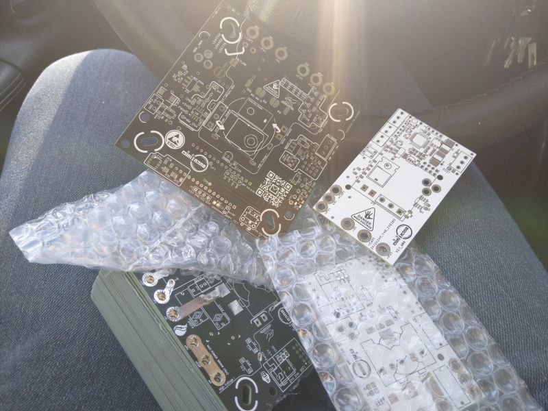
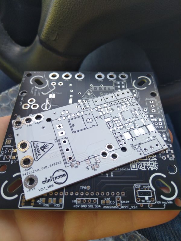
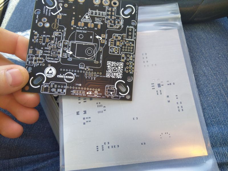
    On a different note, it turns out that time flies quickly and I have just received a shipment with new PCBs.
    This is what they look like...

    New PCB boards wrapped in bubble wrap on a lap.
    Two new PCBs stacked on top of each other on a hand with a car interior in the background. The boards feature markings and spots for electronic components.
    Close-up of a newly received printed circuit board (PCB) held in hand, with other PCBs in transparent packaging in the background.
  • #35 21020145
    dgproject
    Level 13  
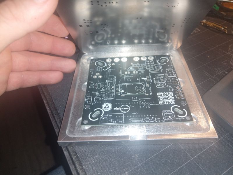
    A person holding a metal stencil above a black PCB.
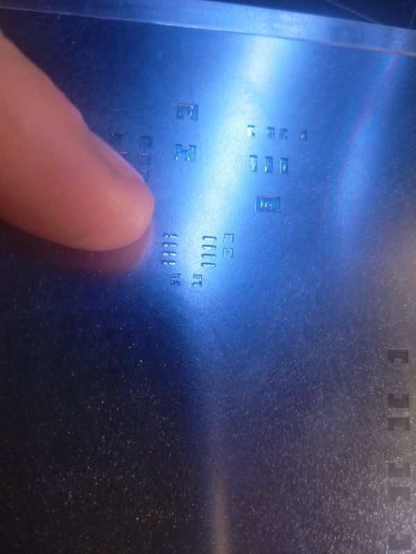
    The stencil fits like a glove.

    A metal stencil with several holes, touched by a finger.


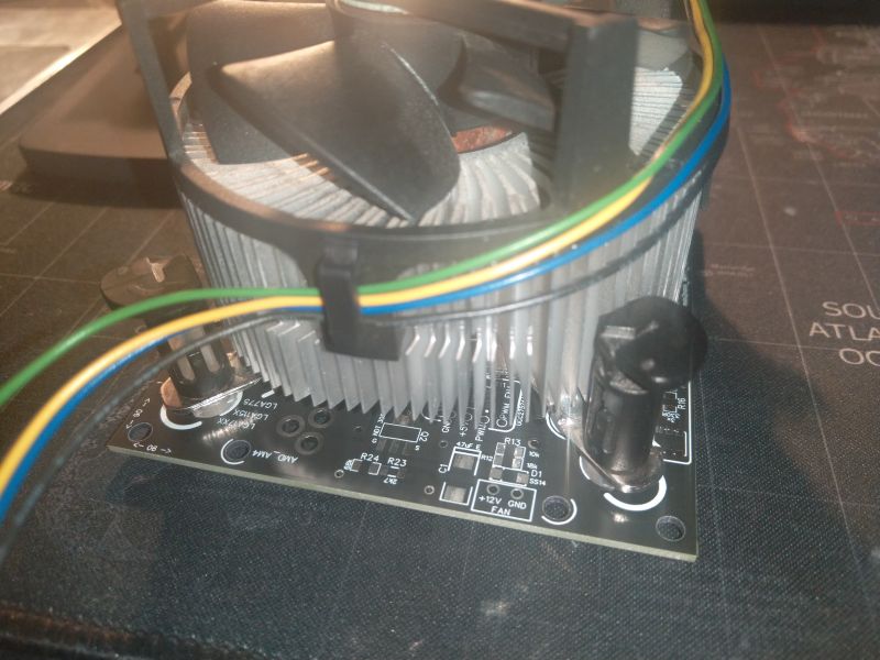
    Heatsink with a fan mounted on a circuit board with colorful cables.
    Holes for cooling as well.


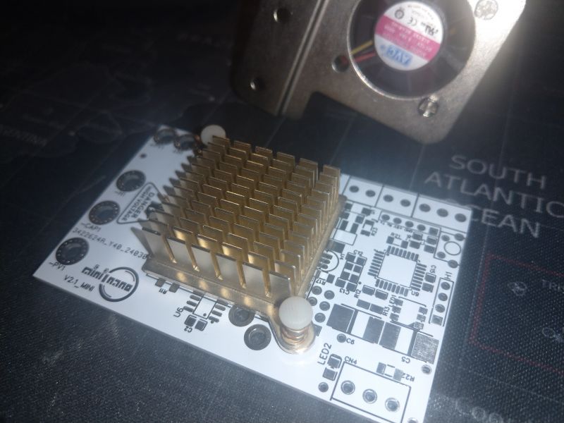
    Circuit board with a mounted heatsink and cooling holes.
    This is what the mini version looks like.


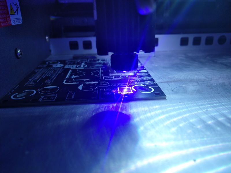
    Testing circuit paths on a PCB using a laser.
    It`s time to sign and test the tracks.
  • #36 21023842
    romulus73
    Level 28  
    dgproject wrote:
    Calculations show that the average daily energy demand for my four-person family is approximately 5.5 kWh in the period from April to November (outside the heating period).


    Hmm, that`s why I built the first heat pump to heat the COUW, in the summer 1 kW was enough for the pump to heat it. So the equivalent is 400 kW. I have an old contract, for me it would be a shame not to send it to the network. Even if I sent your 2000 kW, they return 1600 of this, the pump will take 400, and 1200 remains free (nothing is free).
    Each solution has its pros and cons. But you put it nicely, there`s no money, you have to make your own and it`s no worse than mass-produced ones.
  • #37 21025770
    dgproject
    Level 13  
    romulus73 wrote:
    Hmm, that`s why I made the first heat pump for playing COUW, in the summer 1kW was enough for the pump to heat it.

    Above all, I wanted it to be cheap and reliable.
    No moving parts and cheap to repair if such a situation arises.
    A heat pump is like a refrigerator, you never know what will break down and when.
    For example, my neighbor has been using a Viessmann ground pump since 2014 and has no complaints. Service every year and even relatively low energy consumption. Combined with recuperation, it`s great.
    A friend from work installed a ground-floor heating system in 2009, spending over PLN 60,000, and has been heating his house with gas for two years because his controller broke down and, unfortunately, they have been no longer producing them since 2012.
    In short, the pump needs to be replaced and I can`t afford a new one.
    Maybe I don`t read books, but in recent years I have read many warranty documents for various equipment from A to Z and I am blown away.

    I do not deny the decision to purchase expensive and maintenance-free heating devices and I do not intend to discourage anyone from purchasing them, after all, it is a great comfort that is appreciated these days.
    However, I think that many people, like me, are looking for DIY alternatives to devices available on the market and that is why the material was posted on this forum 😉
  • #38 21051674
    tesla97
    Level 18  
    acctr wrote:
    But what not necessarily? How do you make DC into AC current without electronics? Electromechanically?


    You need a motor with a mechanical inverter. They used to use such in telephony. Such an inverter looks like a commutator motor except that the DC side is two rings on the shaft and on the other side is a normal commutator and it switches the voltage between the wires alternately making DC AC.
  • ADVERTISEMENT
  • #39 21051794
    M.Konopka
    Level 14  
    Still in use today.

    Example 1: Flywheel UPS (although here there is an inverter), very clever concept, powers from 200kVA to many MVA. A few years ago there was one in Poland (Gdansk University of Technology), now I don't know.

    Example 2: Engine coupled UPS or e.g. Diesel Rotary UPS (DRUPS) from Hitec (Hitachi), powers 500kVA-3000kVA. Not to be confused with an ordinary diesel-powered generator or mill wheel. They are different devices.
  • #40 21052103
    acctr
    Level 38  
    tesla97 wrote:
    acctr wrote:
    But what not necessarily? How do you make DC into AC without electronics? Electromechanically?


    You need a motor with a mechanical inverter. They used to use such in telephony.

    This was basically a rhetorical question because electromechanics fit photovoltaics like rubber boots fit a suit, but it is nevertheless good to know.
    Helpful post? Buy me a coffee.
  • #41 21106917
    dgproject
    Level 13  
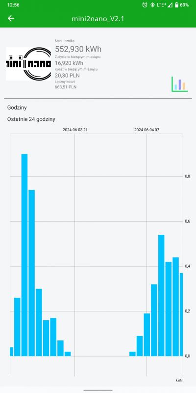
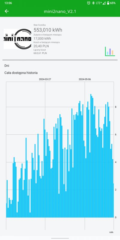
    Screenshot from the SUPLA app showing energy consumption in kWh. .
    Hey, as an update on the progress of my project here are some screenshots of the measurements in the SUPLA app.
    The last two days have been totally cloudy, yet I still can't complain about the lack of hot water.

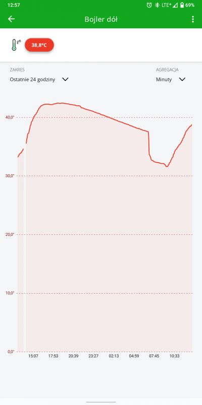
    Temperature chart of the hot water buffer from the SUPLA app. .
    Apparently the heater is only heating with a power of a few hundred watts, but as you can see the buffer temperature is rising.

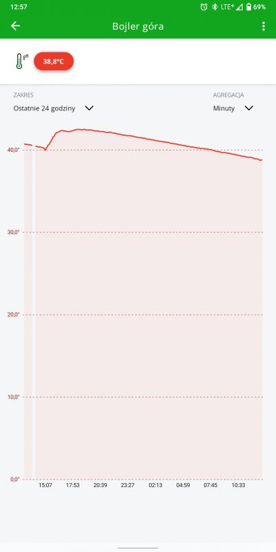
    Temperature chart of the upper part of the boiler in the SUPLA app, showing data from the last 24 hours. .
    The top of the buffer reaches >40°C despite the bad weather conditions.

    Tomorrow, the sunshine will fortunately be hovering for longer.

    Screenshot of the SUPLA app showing energy consumption on a bar chart.
    This is the production from 17.02.2024 until 13:00 today.

    -Not a single milliwatt has been drawn from the grid.
    -Daily bathing habits unchanged.

    In my spare time I am putting together the final version of the controllers.
    I will try to post progress on my YT channel to which you are cordially invited.
    https://youtu.be/VUAgzR0TKas?si=sql0CCPMOywJMtFr
  • #42 21109576
    dgproject
    Level 13  
    https://youtu.be/A9FocZoBwow
    In the material I present the progress on the final version of the controller.
    Chores around the house unfortunately take up valuable time, but the rainy weather is speeding up the overdue projects.
    The final version of the program for Arduino with corrections and schematics is coming soon.
  • #43 21109890
    MarekS6
    Level 16  
    The housing is nice, but maybe it would be worth making some "ears" in it if someone wants to mount such a controller e.g. on a wall (of course with spacers, so as not to block the airflow). They can always be cut off if someone does not need them :-) .

    Of course I'm still keen (but in no rush) for such a controller (preferably fully finished, but without the display and cooling system). Possibly ESP01S I will probably also have in stock. And that's where I have a question, as I've been busy asking before:

    I understand that you also wrote the firmware for the ESP yourself to work with the supla? Because as a supla, I would also like to have it paired with the supla :-) .
  • #44 21109905
    dgproject
    Level 13  
    MarekS6 wrote:
    I understand you also wrote the firmware for the ESP yourself to work with the supla? Because as a supla, I would also like to have it paired with the supla
    .

    On the supla I have it set up as a pulse counter, but the UART option on the board as much as possible is available via the microstick.
    The more advanced programme is unfortunately a bit clumsy for me, so will be in a later post.
  • #45 21109957
    MarekS6
    Level 16  
    aaa, so all those graphs what you show there is a simple pulse counter :-) That's enough as you can see anyway. I thought that the pulse counter shows such things much less clearly :-) In that case, I don't worry about that either, because uploading the Generic Gui version of the supla to the ESP and setting it as a pulse counter is a trifle :-)
  • #46 21110043
    dgproject
    Level 13  
    Exactly like this.
    GuiGeneric version of pulse counter + DS18B20 temperature sensor (I introduced a separate connector with pull-up resistor on the board).
    -The project had to be cheap to build, so that the investment could pay off quickly.
    -It had to offer possibilities for expansion, or adaptation for other purposes.
    As far as I am concerned, the production information recorded with an interval of every 10 minutes is quite sufficient.
    The graphs look clear, but if someone needs to control the Live parameters, go ahead....
    I wanted it to work like this: create, install, forget.
  • ADVERTISEMENT
  • #47 21152257
    dgproject
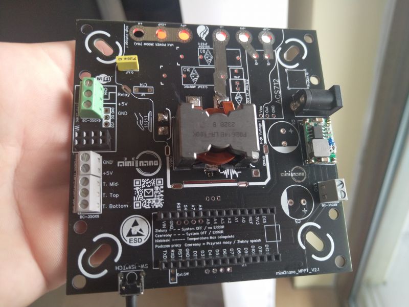
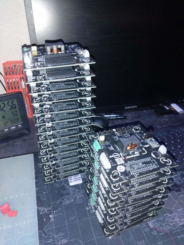
    Level 13  
    Well, I managed to complete the remaining PCBs.
    I currently have over 20 pieces for sale that need retrofitting with a few components.
    Yesterday I received a shipment of the long awaited BURNS chokes.
    The boards require the addition of, among other things:
    -a suitable power Mosfet
    -Shottk diode
    -Arduino NANO
    -Pin sockets under the Arduino
    -ACS712 20A for current measurement
    -Display 2004 I2C
    -ESP-01s e.g. under SUPLA
    -Radiator with thermopad.
    -Socket 2.1 5.5 (for several boards unfortunately missing)
    -Capacitors

    The values of the individual components are plotted on the boards.
    The raster for MKP/ X2 capacitors allows several variations.
    I will make the full batch for Arduino available to those interested, with descriptions, schematics etc.
    I am currently completing the design of a 3D printed enclosure, which I will present on my YT channel.

    https://youtu.be/sZMFd6LIkH0?si=g4favhgzJBzlSOHm

    PCB held in hand, with various connectors and spots for electronic components. .

    A stack of PCB boards on a desk, ready for component assembly.
  • #48 21160919
    dgproject
    Level 13  
    https://youtu.be/bw8CBv540KI

    For those who are interested, I am making the project available to be completed in a few sub-assemblies in the auction posted below the video.
    Until resources are exhausted...
    When all the controllers I have in excess have gone, I will make the entire project available on this forum including the Arduino batch, schematics, Gerber, and instructions.

    Regards
  • #49 21171406
    Kwazor
    Level 33  
    Hi !
    Nice how it all worked out for you except : the power inverter.

    I'm surprised that no one here has caught the massive error in this design.


    1 issue :
    Quote:
    -It is possible to change the frequency for the PWM signal in the range 2kHz - 17kHz
    .

    Too small a core ( AL too and number of turns) here you need an ETD core at least with a large AL to make it work like a real BUCK inverter ( you wouldn't have such mosfet heating and that tells you about the surge current it gets when the key is switched on)--.

    What does it give ( i.e. it doesn't give because there is no chance it is a piece of wire and a noise generator ) when there is a big mismatch between source and load

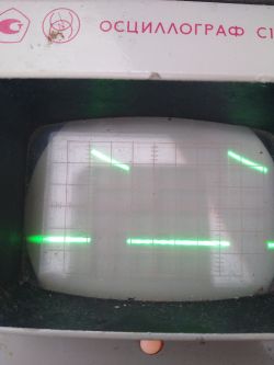
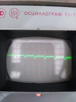
    Do an I U In / I U Out measurement (it would be nice if you connected an oscilloscope to the output) I would not be at all surprised what the waveform is (yes I know the heater can tolerate everything) but the capacitors on the input heated up what ? ( didn't you wonder ? ) I know they work and what they do but they have a difficult job and the storage coil is asleep....

    For example, my inverter had 66V 5A and the output was 12V 26A (this is a car battery) and there was no voltage matching 1:5
    And I take a calm measurement on the input and on the output ( U ripple 0.1V was)

    Why is there no ( almost ) electrolytic capacitor on the output of the inverter ? ( I see only MKT /MKP ? ) because it would boil it .( I did a test in DCM mode --- the input capacitor firing was and the racing ones were swollen....

    If you want even better results, study again the principles of buck converter design (it will heat up, but here, for the time being, the whole herd of input capacitors serves as a buffer), raise the operating F - in my case 80khz (after changing the coil)

    You will decrease losses on the key - you don't need a herd of capacitors on the input - EMI too - you have the possibility to do real power measurement on the output .

    This is what 1kW on 24V looks like with an input U of 80V :
    Power converter with a large coil and capacitors on a PCB. .
  • #50 21171476
    dgproject
    Level 13  
    Kwazor wrote:
    I am surprised that no one here has caught the egregious error in this construction.


    Welcome,
    But no one here is discussing any Buck or bust Converter.
    The project is not the first of its kind in the world and similar designs have been successfully working for many users for years.
    I encourage you to make some interesting reading among others:
    "LoadMaster XP"

    Capacitors, I have to worry you, but cold is like the environment.
    The transistor in my case puts off a bit of heat on the heatsink due to the use of IRFP460 with high resistance during conduction.
    The whole thing runs on an Arduino, so the frequencies oscillate in the lower kHz range.
    Practically for the first year of playing with the project, the oscilloscope was constantly connected to the input and output of the controller.

    I am just finishing assembling a wall of these drivers and would be happy to demonstrate on the YT channel the ripple level and operating temperature of this circuit under a thermal imaging camera.
    I also started out with operational amplifier based inverters and frequencies in excess of a few hundred Hz, but this is nowhere near MPPT circuits.
    In my next project, the operating frequencies will not exceed 700Hz, there will be virtually no capacitors, and the PTC heaters will operate in cascade.
  • #51 21171638
    Kwazor
    Level 33  
    Well then why did you give a diode and a coil ? ( to fill the circuit ? )
    Something you don't see yet but maybe it will guide you to an even better design....

    Analyse : the circuit at a mismatch of 1:8 ( that is weather poor the panels give 20% power ) R of the cells is greater than Robc ( normal )
    PWM 20% approx... 80% of the time it lies and this power you don't use ( normal because you can't key off )

    When the key is not working, you still have extra energy stored in the coil ( greater OUTPUT ).... less surge currents, the system runs smoothly (you have a 20R load, I have a 20mR load), didn't you wonder about the prototype system hanging up? Here you should already think about what causes it ... I call it Boom-Boom circuit - hard key on and a capacitor can give a big impulse and we have an EMP suspending the circuit (optionally the circuit of paths and ground point - this also likes to give a bite)
    The best thing is that the transistor shows when it gets a short circuit ( I had as I wrote the wrong program and the key started with 99% )

    This is not a fad of mine but 9 years ago I struggled with this matter and some lessons were learned....

    A good BUCK with this design will give excellent results....

    As for the small F of the arduino: you can always give an external generator and you have a higher F (I didn't have to because my proc gives up to 120Khz)
  • #52 21171880
    dgproject
    Level 13  
    Kwazor wrote:
    PWM 20% approx. 80% of the time you are lying around and this power is not used ( normal because you can't key off )
    .
    I would disagree with this term.
    The PWM in these circuits does not function linearly and has the ability to define fill thresholds in the code which I use too.
    Kwazor wrote:
    were you not puzzled by this hanging of the prototype circuit ?
    .
    The program crashing only occurred on the ESP and as it turned out, the problem had nothing to do with the EMP, but with the inadequacies of these chips while using WiFi.
    The Arduino is reliable and runs so smoothly that I only blow the dust off the heatsink once a month.

    As for the power, as soon as it dawns practically the first 100W of power starts to raise the temperature in the lower part of the tank, which is very cool to see in the measurement from the Supli.

    Kwazor wrote:
    This is not a fad of mine just 9 years ago I struggled with this matter and some lessons have been learned..
    .

    Provide a link to your project, I'm curious what the comparison is about.
  • #53 21172236
    Kwazor
    Level 33  
    What it will show you :
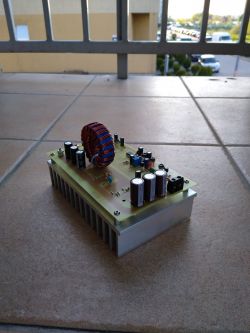
    An arrangement similar to yours :
    Advanced DIY controller for heating utility water from a photovoltaic installation. .

    Layout with full buck :
    Advanced DIY controller for heating utility water from a photovoltaic installation.

    Now see how much extra energy was given by the stored energy in the coil ( magnetised when the key is switched on --gives up when switched off .

    Yes you see it will also heat but it can be even better....

Topic summary

The discussion revolves around the development of an advanced DIY controller for heating utility water using a photovoltaic installation. The original poster shares their experience with a balcony solar setup that powers their home, detailing modifications made to reduce energy storage costs. Participants discuss various aspects of the project, including the design of the controller, the use of an H-bridge for AC output, and the importance of safety measures to prevent arcing in high DC voltage applications. The conversation also touches on software development, component sourcing, and the potential for community collaboration through platforms like GitHub. Users express interest in monitoring capabilities via the Supla application and share insights on component selection, including MOSFETs and capacitors. The project aims to be cost-effective and reliable, with plans for future enhancements and community sharing of designs and schematics.
Summary generated by the language model.
ADVERTISEMENT