logo elektroda
logo elektroda
X
logo elektroda

How To Flash T34-Based Smart Switch from Aliexpress With Tasmota/Esphome style firmware OBK

Mati Crawn 13338 78
ADVERTISEMENT
  • #31 21321513
    marekvnl
    Level 9  
    p.kaczmarek2 wrote:
    What connection? Any photos?
    .

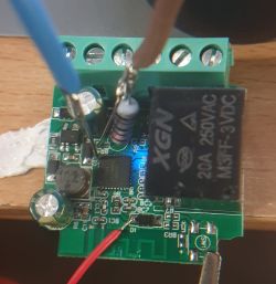
    Close-up of an electronic module with soldered wires and a visible XGN relay. .

    p.kaczmarek2 wrote:
    This problem is quite well known and has already appeared on the forum, the symptoms are quite deceptive, reading works and writing breaks down, but it all usually comes down to improving the power supply, shortening the cables, possibly changing the USB to UART converter, or a different baud rate. It's also sometimes worth trying a higher baud, as a lower one gives errors (and vice versa).


    Thank you for the helpful suggestions. I changed the UART converter, shortened the cables and stabilised the power supply better. It went off without a problem.

    Getting bus success!
    Going to set baud rate setting (115200)!
    Will try to read device flash MID (for unprotect N):
    Flash MID loaded: 15701C
    Will now search for Flash def in out database...
    Flash def found! For: 15701C
    Flash information: mid: 15701C, icName: EN25QH16B, manufacturer: ESMT, szMem: 1000000, szSR: 1, cwUnp: 0, cwEnp: 7, cwMsk: 3C, sb: 2, lb: 4, cwdRd: 05-FF-FF-FF, cwdWr: 01-FF-FF-FF
    Entering SetProtectState(True)...
    sr: 0
    final sr: 0
    msk: 3c
    cw: 0, sb: 2, lb: 4
    bfd: 0
    SetProtectState(True) success!
    Going to do erase, start 69632, sec count 281!
    Erasing sector 69632... ok!
    (...)
    All selected sectors erased!
    Writing sector 0x11000... ok! 
    (...)
    CRC matches 0x99ADEB79!
    
    NOTE: the OBK config writing is disabled, so not writing anything extra.
    Writing file data to chip successs.[/quote]
    
    Dziękuję za pomoc, pozdrawiam serdecznie!
    .

    Edit:

    Sorry for the edit, let me still include a follow-up question.

    Flash went OK. I tried the first one without uploading the OBK configuration. I disconnected the UART and connected the device to 230VAC. I expected it to expose the AP to the first configuration like Tasmota, but it didn't (I've flashed something with openbeken before and I think that's how it worked). The device came back on the tabletop with the UART connected, but monitoring the console unfortunately I wasn't even able to see the bootloader. During the hard reboot Realterm was only showing one break event. I tried the reflash a second time, adding the config as below and also checking flag 31 - Enable UART Command Line.
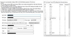
    Screenshot of the tool for configuring and flashing a device with OpenBeken. .

    Both the firmware and the config uploaded without issue. Unfortunately in this case I could not see any output to the console from the boot process either. One break event and that was it. Realterm set to 115200 8N1 as standard. I also tried other speeds.
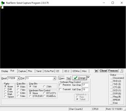
    RealTerm program interface with serial port settings. .

    When connected to 230VAC, as I expected, the device did not connect to the configured wifi network or put up its AP. I tried putting it literally next to the access point, just in case the anetna was that weak, but it didn't do anything.

    I did erase and flash a few more times with different combinations of firmware versions (latest OpenBK7231N_QIO_1.17.777.bin and older) and OBK config but no success.

    Out of curiosity I also plugged in UART2 (Pin 27 RX, Pin 28 TX) but there was no activity there either.

    Could it be that the bootlader is compacted? I didn't combine anything manually around 0x0 and only used bk7231flasher_1.3.3.

    Do you have any idea how to debug this further?

    Thanks a lot, regards!
  • ADVERTISEMENT
  • #32 21323010
    p.kaczmarek2
    Moderator Smart Home
    As long as you have a copy of the original 2MB batch, upload it, and then write OBK on it. You may have done a full erase for yourself.

    If you don't have a copy of the original batch, then upload the OBK with the bootloader:
    Spoiler:
    .
    BK7231 Easy UART Flasher user interface with selected settings for flashing. .
    .

    Also, you can try uploading any 2MB dump for the N platform from my base and then record OBK on it:
    https://github.com/openshwprojects/FlashDumps/tree/main/IoT/BK7231N

    PS: The activity is supposed to be TX2, if there's nothing there then the bootloader has probably cleared, but as I wrote above you can fix it.
    Helpful post? Buy me a coffee.
  • #33 21323031
    marekvnl
    Level 9  
    p.kaczmarek2 wrote:
    PS: The activity is supposed to be TX2, if there is nothing there, then the bootloader has probably removed itself, but as I wrote above, you can fix it.
    .

    Thank you very much, I used the "overwrite bootloader" option (I thought of this before but was confused by the "for N/M don't use it" note) and the output on UART2 came to life.

    The device is now booting and working properly.

    I attach a snapshot of the original batch, as if anyone ever needs it.

    Thank you and best regards!
  • #34 21323046
    p.kaczmarek2
    Moderator Smart Home
    Because in general you shouldn't perform overwrite bootloader, but from the description of the situation it seems that you have already removed it for yourself. Hence the need to do so.
    Helpful post? Buy me a coffee.
  • #35 21323324
    no_cloud
    Level 6  
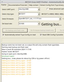
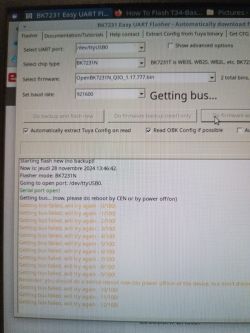
    Hello, I don't start the connection.
    Ubuntu and mono BK7231Flasher.exe
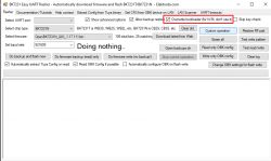
    Screenshot of BK7231 Easy UART Flasher program displaying connection error messages.
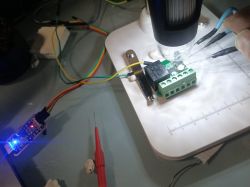
    TX of TTL to RX and RX of TTL to TX
    3V3 of USB UART and GND
    I touch the GND for CEN many times, I have many blue LEDs blinking (if I stay on the GND, she stops in blue or in black)
    I have reversed RX and TX for test but nothing.
    Thank you for any help.
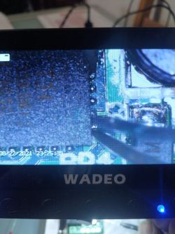
    Close-up of an electronic circuit with a connected module via wires and USB UART. Close-up of a display showing an image of an electronic circuit board, with the label WADEO visible.
  • #36 21323333
    divadiow
    Level 35  
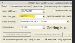
    T34 is BK7231N chip not BK7231T

    Screenshot of BK7231 Easy UART Flasher program with BK7231T option highlighted.

    and have you tried lower baud rates? 115200
  • #38 21323451
    max4elektroda
    Level 20  
    no_cloud wrote:
    3V3 of USB UART

    This might be a problem, too. You might also try to use another power supply. This adapters usually only supply a very limited current.
  • ADVERTISEMENT
  • #39 21323475
    p.kaczmarek2
    Moderator Smart Home
    divadiow wrote:
    T34 is BK7231N chip not BK7231T

    You are right, but it should still at least start the flash process. So there must be other issue elsewhere.


    See related guides, BK7231N and new flash tool:


    BK7231N and old flash tool (hid_download_py):


    Helpful post? Buy me a coffee.
  • #40 21323531
    no_cloud
    Level 6  
    >>21323475 thanks, I have seen this videos ;-)

    Added after 26 [minutes]:

    ok, i have changed the baud rate and changed type (7231N)
    but nothing.
    I take this video for you see the blinking, it's ok after the reset action?
    Computer screen with BK7231 Easy UART Flasher application showing error messages.


    Big thank for your help!

    Added after 35 [minutes]:

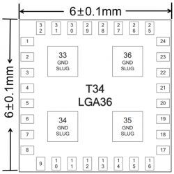
    CEN is the pin 9? it's ok for you?
    I try 29 or 9 but nothing
    Pin layout diagram of T34 LGA36 package.
  • #41 21323731
    p.kaczmarek2
    Moderator Smart Home
    I personally don't use CEN method anymore, disconnecting power off and on seems more reliable in my opinion. Of course, you have to disconnect just VDD wire, not whole USB to UART converter...
    Helpful post? Buy me a coffee.
  • #42 21323765
    no_cloud
    Level 6  
    p.kaczmarek2 wrote:
    I personally don't use CEN method anymore, disconnecting power off and on seems more reliable in my opinion. Of course, you have to disconnect just VDD wire, not whole USB to UART converter...

    YES!!! Big thangs, the adventure continues ;-)

    Added after 32 [minutes]:

    oups, i want reflash but the T34 with openbeken don't blink in blue with this method, i have don't see a instruction for that?
    i'm sorry, it's my first flash with T34 ;-)
  • #43 21323829
    max4elektroda
    Level 20  
    no_cloud wrote:
    reflash but the T34 with openbeken don't blin

    Reflash means, the device already was flashed with OpenBeken?
    Then it's much easier to flash another version over the air using the present version (Web Application).
    If not: did you try another power source?

    Added after 3 [minutes]:

    If I remember correctly, my led was permanently lit low in blue during flashing.
  • #44 21323865
    no_cloud
    Level 6  
    Mati Crawn wrote:
    {
          "vendor": "Tuya",
          "bDetailed": "0",
          "name": "WiFi Switch",
          "model": "",
          "chip": "BK7231N",
          "board": "T34",
          "keywords": [
            "",
            "",
            ""
          ],
    "pins": {
    "6": "LED_n;0",
    "14": "TglChanOnTgl;0",
    "15": "Rel;0",
    "24": "TglChanOnTgl;0"
          },
          "image": "https://obrazki.elektroda.pl/5168873200_1714224899.png",
          "wiki": "https://www.elektroda.com/rtvforum/topic4051203.html"
        },

    how import your config in web app?
  • #46 21324762
    no_cloud
    Level 6  
    >>21324039 Thank you, I have not seen this tutorial.

    Added after 22 [minutes]:

    Very nice job!!!
    Web application is simple and perfect, good job!
  • #47 21327734
    no_cloud
    Level 6  
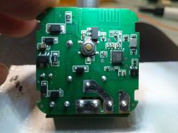
    I have this variant.
    Close-up of a green circuit board with various electronic components.
    Should I post this variant somewhere on the site and then share it?

    Do you have an idea for the ground and the 3V3?
  • ADVERTISEMENT
  • #48 21327748
    p.kaczmarek2
    Moderator Smart Home
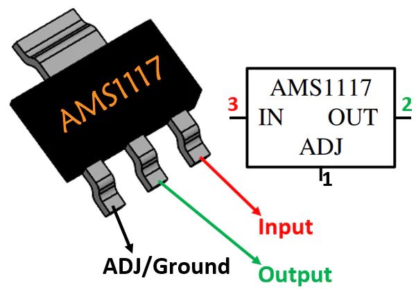
    One of good and reliable methods of finding GND and 3.3V pins is to look for the LDO regulator on the board. Your board has AMS1117-3.3V available, which pinout is widely known, as shown below:

    Diagram of AMS1117 regulator with pin labels.
    Helpful post? Buy me a coffee.
  • #49 21327808
    no_cloud
    Level 6  
    Big thanks but I have tried many times.
    I have not the alimentation, I have not the led blinking.

    A other day, maybe ;-)
  • ADVERTISEMENT
  • #50 21335520
    leonardocapone
    Level 4  
    Hi there! Just a quick tip for those who found it difficult to get T-34 into programming...
    I've kept pressing the small onboard push button and it seems to me an easier "way-out" instead of cycling power.

    Moreover and just for your info, I've received 4 of those t-34 based mini smart switches...at first they looked the same...however, I found one of them slightly different in dimensions;
    for that, LED pin is not 6, but 24...I guess that comes from a different manufacturer or it is an updated/previous version

    Have a good one!
    L.
  • #51 21336094
    zilplayzil
    Level 2  
    Hello!
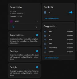
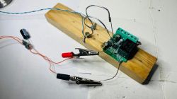
    After programming with OpenBK and activating in Home Assistant via MQTT I only got On/Off, the other information is inactive. Do you have any ideas?

    Screenshot of the Home Assistant user interface with device and MQTT diagnostic information. Simple electronic setup on a wooden board with a relay, capacitor, and wires with clips.
  • #52 21336884
    p.kaczmarek2
    Moderator Smart Home
    For a quick test, you can manually run publishAll/b] command in OBK and check if it changes anything. Then you can make sure if "publish" flags are enabled, there are flags like "publish self state on MQTT connect" ,etc
    Helpful post? Buy me a coffee.
  • #53 21339157
    zilplayzil
    Level 2  
    publishAll worked !
    and
    Flag 19 - [MQTT] Always publish channels used by TuyaMCU
    Flag 2 - [MQTT] Broadcast self state every N (def: 60) seconds (delay configurable by 'mqtt_broadcastInterval' and 'mqtt_broadcastItemsPerSec' commands)

    Thank you for your help!
  • #54 21352116
    no_cloud
    Level 6  
    >>21327748
    ok, it's the good alimentation, I have blue blink.
    But I can't flash.
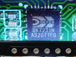
    I have this component, it's the same as T34?
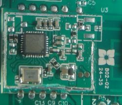
    Close-up of BK7231N integrated circuit on a circuit board.
  • #55 21352205
    zilplayzil
    Level 2  
    Yes, T34 is a cod for BK7231N.
  • #56 21352245
    no_cloud
    Level 6  
    >>21352205
    thanks, I retry ;-)

    Added after 1 [hours] 2 [minutes]:

    i'm sorry, i have not falshing thos model.
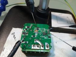
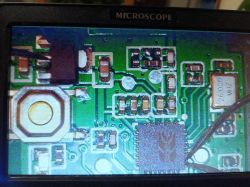
    i takes photos, do you have a idea?
    i post video for binking.
    Circuit board with attached probes on a desk.
    Close-up of a circuit board with electronic components under magnification.


  • #57 21352342
    divadiow
    Level 35  
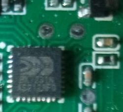
    how come you're going for the legs directly? are these two test pads not RX/TX?

    Close-up of a circuit board with an integrated circuit and traces.
  • #58 21353401
    no_cloud
    Level 6  
    >>21352342
    Thanks for your help.
    I can try your idea but I think, it's not my problem ... maybe.
  • #59 21354495
    no_cloud
    Level 6  
    >>21352342
    Hello, you are in the right, it's pass for test but not for TX, just RX.
    I try this morning....
  • #60 21355507
    no_cloud
    Level 6  
    >>21352342
    I think you are in the right!
    I have no T34 but bk7231n and I have read pins is not the last and before but just one before.

    I have moved TX and RX but nothing.
    I don't understand.

    I post 2 videos.
    First for you see my installation (maybe I have a problem? (green for TX in my USB/TTL in bottom in my BK)
    The second video is for the blinking.
    I have seen 3 blinking different, slowly, middle and very fast.
    I think very fast is for flashing.... no?

    ps: my dupont power pin is very bad and a little move is perfect for <250ms stop power and I see the TX light green. It's ok.

    Any help is very appreciated for me. I working 3 days and I have no results.

    Big thanks!!


Topic summary

The discussion focuses on flashing T34-based smart switches purchased from AliExpress, which use the BK7231N chip, with custom firmware such as OpenBeken (OBK), Tasmota, or ESPHome-style firmware. Two hardware variants were identified: one with the pushbutton on the back and another on the front, both sharing the same baseboard design. Users encountered challenges flashing these devices using the Tuya Cloudcutter due to firmware version 1.3.10 being non-flashable via cloud methods. Successful flashing requires direct UART access, often achieved by soldering or using needle pins on test pads or chip pins 25 (RX) and 26 (TX). A pull-down resistor labeled BR4 on the PCB aids in accessing the TX pin. Power supply stability is critical; USB-TTL adapters often lack sufficient current, so external 3.3V power supplies or powering through the AMS1117-3.3V regulator input are recommended. Short, direct wiring and proper connection of RX/TX lines (crossed correctly) are essential to avoid communication errors. Flashing tools like BK7231Flasher sometimes fail due to power or connection issues; alternatives like hid_download_py have proven more reliable. Some users reported needing to overwrite the bootloader to restore UART functionality. For newer or different board revisions, microsoldering and hardware modifications (removing resistors/capacitors) may be necessary. The community shared various soldering techniques, including solder-less needle pin methods and glue gun fixtures for stable connections. MQTT integration with Home Assistant works well after flashing, though some configuration flags may need adjustment to enable full telemetry. Additionally, a variant with an unmarked RF chip (possibly SYN531R) was discussed, with suggestions to analyze its protocol for remote control support. Overall, the thread provides detailed practical advice on hardware identification, wiring, power considerations, flashing procedures, and firmware configuration for T34/BK7231N smart switches from AliExpress.
Summary generated by the language model.
ADVERTISEMENT