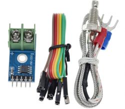
The K-type thermocouple together with the MAX6675 A/D converter module allows you to easily measure high temperatures from 0°C to 800°C with 12-bit resolution. The kit presented here operates on a voltage from 3 V to 5.5 V and uses a simple SPI protocol for communication, which can be equally well implemented on any three GPIOs of the selected microcontroller.
Let's probably start with the most important thing, i.e. the price - at the moment of writing this topic, the whole kit can be bought with shipping for a few tens of zlotys in our country, and importing from China we can close in the amount of 10 zlotys.

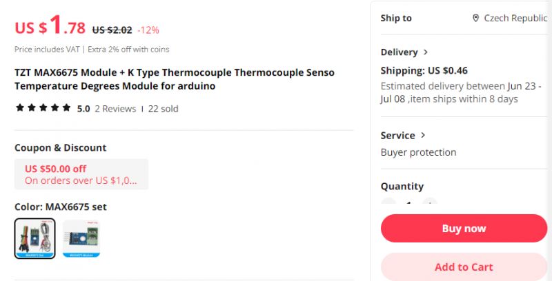
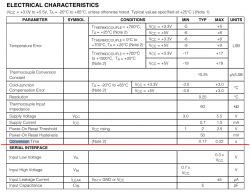
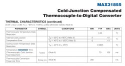
It is only important to order the whole set, and not accidentally the module alone with the MAX6675.... and by the way let's have a look at its catalogue note:
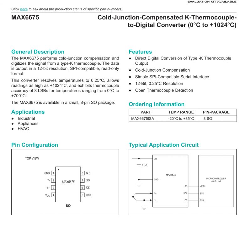
The connection to the MCU seems to be very simple, only three lines are needed
MISO, SCK, SSB, but let's not forget also the common ground and the power supply.
The SPI protocol - it sounds scary, but in practice here SPI is used in the simplest possible way. The datasheet note describes how the communication is done:
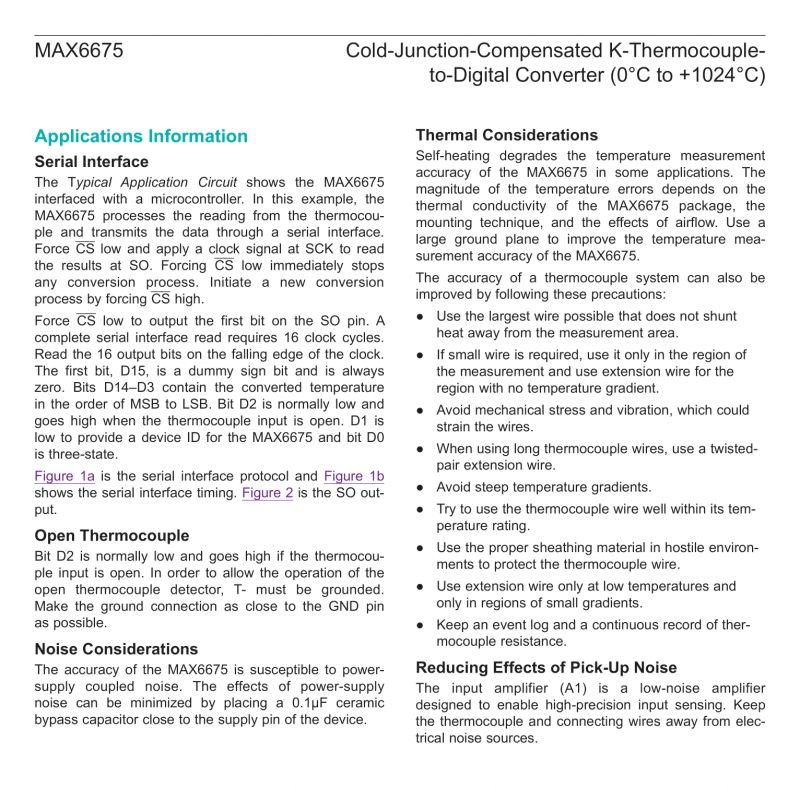
Visually presented communication:
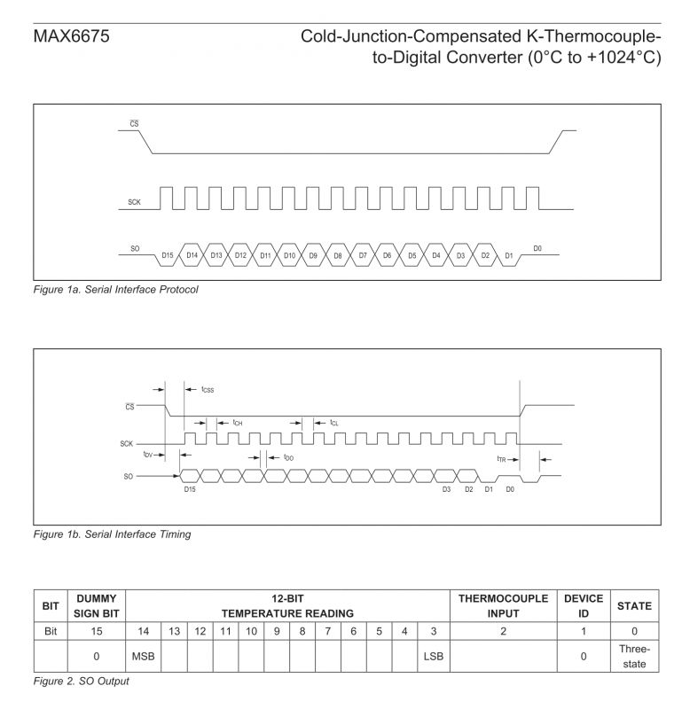
So basically we set the CS to a low state, then manipulate the clock and read the next bits from the SO. The whole thing has to be done at the same time respecting the timings, but everything is on the diagram. The meaning of the 16 bits read is also defined in the diagram - we are mainly interested in the 12 bits of measurement, i.e. bits 3 to 14 inclusive.
Now the question of how to use this with the MCU - well, the best way is to use a ready-made library, there are plenty of these under the Arduino:
https://www.arduino.cc/reference/en/libraries/max6675/
It can be added via Library Manager.
Here's another library:
https://github.com/adafruit/MAX6675-library
For most people you could end here, but anyway now we'll take a look at how this communication is implemented internally.
We don't use hardware SPI here - any digital GPIO will suffice:
Code: C / C++
For reading we have 16 bits, so two bytes. You will need the function that reads the byte:
Code: C / C++
In the loop we set the clock to a low state, wait a moment and then read the data from MISO. Then we set the clock to a high state and wait, after which the loop repeats.
There is still manipulation of the CS pin missing, but this we have outside this function:
Code: C / C++
Here we also read both bytes and assemble them into a single 16-bit word (although you could just as well read the whole 16 bits at once in spiRead).
Then we need to interpret the read data. Here we have a bit more than the measurement itself...
Code: C / C++
One of the bits allows us to check if the measurement was successful at all. This can be useful when looking for errors. After checking the error, we simply shift the whole thing by 3 bits (to "cut off" the three youngest bits) and then multiply by 0.25 to get the result in degrees.
And that's it - we already have the measurement. As you can probably see, this is very easy to implement on practically any MCU and those proud SPI's of the offerings are not at all so terrible in this case.
What can this be used for? In my case, the kit with the MAX6675 is useful for hot air testing:
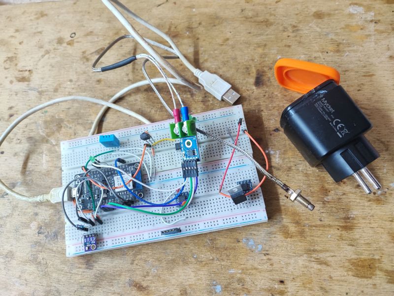
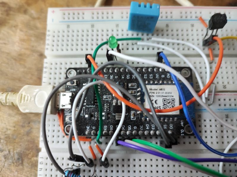
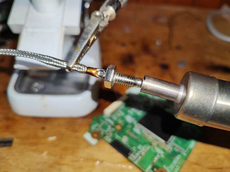
This is extremely useful for me, because, as I have found out over time, the temperature actually 'seen' by the PCB can differ significantly from the temperature on the display of the hot air station, depending on which station you have and what blowing you set. I document my measurements and put them on interactive graphs ( version 350°C , version 450°C ).
In summary, the kit with the MAX6675 is very cheap and at the same time easy to run, beginners should have no problem with it, as well as it should run on slightly less familiar MCUs, I even ran it myself on BK7231 , although in principle the same code will run on all platforms supported by OBK .
I invite you to discuss. Have any of you also used the MAX6675 in your projects? What are your experiences with this chip, or would you prefer an alternative?
Cool? Ranking DIY Helpful post? Buy me a coffee.


