logo elektroda
logo elektroda
X
logo elektroda

Xiaomei Fish Feeder WIFI002_V20 Belon BL2028N OpenBK7231N Flash Issue

Nordlicht77 4125 35
Best answers

How can I get OpenBK7231N/OpenBeken to boot on the Xiaomei Fish Feeder BL2028N when flashing the usual image reports success but the device never shows up on Wi‑Fi?

Use the device-specific bootloader and partition layout first, because this fish feeder does not boot correctly with a normal OBK flash alone and OTA starts at 0x143000 [#21097170] The working procedure reported was: flash the bootloader from the Discord thread with ltchiptool-v4.11.1, reboot, then flash the unencrypted OpenBK build from the Dogness thread (OpenBK7231N_App_UA_1.0.0.bin from test20240601.zip) with ltchiptool [#21107162] If the first write still does not bring up Wi‑Fi, reflashing the OpenBK image at start address 0x0 fixed it and the AP appeared [#21107685] After that, the device could connect to Wi‑Fi and be configured from the web UI [#21107162]
Generated by the language model.
ADVERTISEMENT
  • #31 21115935
    p.kaczmarek2
    Moderator Smart Home
    You need to open it via OBK panel:
    BK7231T control panel with configuration options and buttons to launch a web application.
    Then it will work:
    Screenshot of an IoT device configuration page.
    Helpful post? Buy me a coffee.
  • ADVERTISEMENT
  • ADVERTISEMENT
  • #33 21224541
    tahunasky
    Level 4  
    Hi,

    I managed to flash with OpenBK7231M_QIO_1.17.678.bin
    I can connect to the fishfeeder and modify settings etc.

    As with @Nordlicht77 I tried to extract config from tuya binary using bk7231flasher_1.3.3, but I get the error:

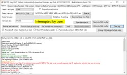
    Failed to extract Tuya keys - magic constant header not found in binary


    I have attached the tuya config bin .

    I have since tried to set it up manually.

    Here is the template I copied from @Nordlicht77 here and tried using, but it didn't work for me:
    {
      "vendor": "Tuya",
      "bDetailed": "0",
      "name": "Full Device Name Here",
      "model": "enter short model name here",
      "chip": "BK7231N",
      "board": "TODO",
      "flags": "-2147483648",
      "keywords": [
        "TODO",
        "TODO",
        "TODO"
      ],
      "pins": {
        "0": "LED;5",
        "1": "WifiLED;4",
        "4": "WifiLED_n;0",
        "7": "dInput;1",
        "9": "dInput;3",
        "15": "Rel;2",
        "22": "dInput_n;7",
        "23": "LED;6"
      },
      "command": "backlog",
      "image": "https://obrazki.elektroda.pl/YOUR_IMAGE.jpg",
      "wiki": "https://www.elektroda.com/rtvforum/topic_YOUR_TOPIC.html"
    }


    And the autoexec.bat .
    setChannelLabel 1 "Endstop"
    setChannelType 1  Toggle
    setChannelLabel 2 "Motor"
    setChannelType 2  Toggle
    setChannelLabel 3 "Button"
    setChannelType 3  Toggle
    setChannelLabel 5 "LED Red"
    setChannelType 5  Toggle
    setChannelLabel 6 "IRRecv"
    setChannelType 6  Toggle
    
    alias buttonevent backlog setChannel 2 1;addRepeatingEvent 10 3 setChannel 3 0
    addChangeHandler Channel1 == 1 backlog setChannel 2 0
    addChangeHandler Channel3 == 1  buttonevent 
    
    setChannelLabel 4 "Wifi Status"
    setChannelType 4  Toggle
    addChangeHandler WiFiState == 4 setChannel 4 1 "Online"
    addChangeHandler WiFiState != 4 setChannel 4 0
    
    alias mode_wifi_on backlog setChannelLabel 4 "Wifi On"
    alias mode_off        backlog setChannelLabel 4 "Wifi Off"
    addChangeHandler WiFiState == 4 mode_wifi_on
    addChangeHandler WiFiState != 4 mode_off
    
    setChannelType 7  Toggle
    alias futterstandleer backlog setChannelLabel 7 "Futter leer";setChannel 5 1;
    addChangeHandler Channel7 == 0  futterstandleer
    alias futterstandok backlog setChannelLabel 7 "Futter ok";setChannel 5 0;
    addChangeHandler Channel7 == 1  futterstandok


    I can toggle the relay on, however it doesn't auto toggle off, when the feed tray has done a complete cycle, so it just keeps on opening and shutting the feed tray endlessly.

    MQTT is working as it should, here is message when I toggle on and off tray:

    root@pi5:~# mosquitto_sub -t 'fishfeeder1/#' -F '@H:@M:@S  %t - %p'
    12:21:29  fishfeeder1/connected - online
    12:21:34  fishfeeder1/2/get - 1
    12:21:47  fishfeeder1/2/get - 0


    I can open and close tray using mqtt:
    root@pi5:~# mosquitto_pub -t 'fishfeeder1/2/set' -m '1'
    root@pi5:~# mosquitto_pub -t 'fishfeeder1/2/set' -m '0'


    Interior view of a fish feeder with electronic components, highlighted switch, and infrared sensor.
    Highlighted in green in the above you can see the switch for feeder tray and infrared sensor for feed level.

    These are the inputs I have figured out from GPIO FINDER in webapp, which match what was in previous posts by @Nordlicht77.
    P0 LED RED (i guess wifi indicator)
    P1 LED BLUE
    P4 Wifi Status ?
    P7 Switch for open/close indicator of feed tray. High is open. Low is shut.
    P9 Rear top button to activate feed tray manually
    P15 activate motor for feed tray.
    P22 Feed bin IR sensor
    P23 IR Sensor enable

    How do I configure them in openbk so that the feed tray stops when P7 switch is activated ?.

    Thanks
    Attachments:
    • BK7231N_TuyaConfig_obk8C000000.bin (72 KB) You must be logged in to download this attachment.
  • ADVERTISEMENT
  • #34 21225681
    tahunasky
    Level 4  
    I have managed to get it working mostly. The issue I was having is that the autoexec.bat wasn't being saved between boots. However, after disconnecting / reconnecting to power a few times, then leaving off overnight it seems to be saving the autoexec.bat now.

    The other issue is that the P0 and P1 settings are different from what @Nordlicht77 has. Initially, he had pins "0": "LED;63", and "1": "WIFLED;62", then changed them to pins "0": "LED;5", and "1": "WIFILED;4",
    When I set to pins "0": "LED;5", and "1": "WIFILED;4", the LED has a pink colour as both blue and red LEDs are on.

    In GPIO FINDER:
    When I click on SET OUTPUT HIGH to turn P0 / P1 off it sets it to pins "0": "LED;63", "1": "WIFILED;63", and the LEDs are turned off.
    Screenshot of GPIO Doctor Pins tool showing settings buttons and output status.
    When I click on SET OUTPUT HIGH again the pins are set to "0": "rel;63", "1": "rel;62", and the LEDs stay turned off.
    Screenshot of GPIO Doctor interface with pin settings.
    When I click on SET OUTPUT HIGH for pin 1 it stays "1": "rel;62", and the blue LED is turned on.
    Screenshot of the GPIO Doctor interface showing settings for pins P0 and P1.

    Should I leave as "0": "LED;63", "1": "WIFILED;63", ?
    I am guessing it sets to "0": "rel;63", "1": "rel;62", as that is the default label?

    @Nordlicht77 why did you change the pins to "0": "LED;5", and "1": "WIFILED;4", ?

    Below is my autoexec.bat which mostly works. But I can not work out how to set the setChannelLabel 3 "Button" to red on startup, remove the word toggle from setChannelLabel 40 "Food Sensor" 1 - bHideTogglePrefix of 1 doesn't seem to work, and hide both setChannelLabel 63 "LED Red" 1 and setChannelLabel 62 "LED Blue" 1 from UI - setChannelVisible 63 0 doesn't seem to work.. or have I stuffed it up ?

    I would only like to see Button, Food and Food Sensor on UI.

    // Feed tray position switch
    setChannelLabel 1 "Endstop"
    setChannelType 1  Toggle
    setChannelVisible 1 0
    
    // Feed tray motor enable
    setChannelLabel 2 "Motor"
    setChannelType 2  Toggle
    setChannelVisible 2 0
    
    // Rear manual feed button
    setChannelLabel 3 "Button"
    setChannelType 3  Toggle
    
    // Feed level IR sensor enable
    setChannelLabel 40 "Food Sensor" 1
    setChannelType 40  Toggle
    
    // Red LED
    setChannelLabel 63 "LED Red" 1
    setChannelType 63  Toggle
    setChannelVisible 63 0
    
    // Blue LED
    setChannelLabel 62 "LED Blue" 1
    setChannelType 62 Toggle
    setChannelVisible 62 0
    
    
    alias buttonevent backlog setChannel 2 1;addRepeatingEvent 10 3 setChannel 3 0
    addChangeHandler Channel1 == 1 backlog setChannel 2 0
    addChangeHandler Channel3 == 1  buttonevent 
    
    setChannelLabel 4 "Wifi Status"
    setChannelType 4  Toggle
    setChannelVisible 4 0
    addChangeHandler WiFiState == 4 setChannel 4 1 "Online";setChannel 62 1;
    addChangeHandler WiFiState != 4 setChannel 4 0;setChannel 62 1;
    setChannelVisible 4 0
    
    setChannelLabel 7 "Food"
    setChannelType 7  Toggle
    alias food_out backlog setChannelLabel 7 "Food out";setChannel 63 1;
    addChangeHandler Channel7 == 0  food_out
    alias food_ok backlog setChannelLabel 7 "Food ok";setChannel 63 0;
    addChangeHandler Channel7 == 1  food_ok


    Screenshot of the OpenBK7231N system interface displaying various settings and system information.

    Thanks
  • ADVERTISEMENT
  • #35 21337194
    zhuangruke
    Level 1  
    >>21097045 Hello, have you tried flashing ESPHome firmware? Does it work?

    Thank you.
  • #36 21451117
    divadiow
    Level 38  
    just adding that the firmware from this device boots on XH-CB2S module where efuse key is 00000000 00000000 00000000 00000000

    I was not able to get the backup you posted earlier into pairing mode though, however many times I grounded P9. I notice there are two other dumps in that Discord thread and one of them starts in pairing mode.

    TX2 is silent. TX1:
    Code: Text
    Log in, to see the code


    and paired by the XiaoMei Smart app
    List of smart devices in the app, including the fish feeder WP8621N. Device addition screen with illustration of router and cloud Smartphone app screen showing room selection option. App screen with an intelligent fish feeder Smart fish feeder app settings interface Smart fish feeder app displaying information on last feeding and water cleanliness. Screenshot showing location management with information about room, MAC address, and device firmware version.

    XiaoMei_WP8621N_Fish_Feeder_WIFI002_V20_WP8621NK_03.bin
    https://github.com/openshwprojects/FlashDumps/tree/main/IoT/BL2028N

Topic summary

✨ The discussion centers on flashing and configuring the Xiaomei Fish Feeder device, which uses the BK7231N/BK7231M chip and Belon BL2028N board, with OpenBK7231N firmware. The main challenge is successfully flashing the device with OpenBK7231N_App firmware and achieving WiFi connectivity and device visibility on networks like Fritzbox. Initial attempts using standard OpenBK7231N_QIO binaries report successful flashing but no network presence. The device uses an unusual bootloader (version 1.0.13) and partition layout, requiring a specific kickstart bootloader (bk7231n-kickstart-ota-1.0.13-0x143000-no-encr.bin) to enable OpenBeken firmware compatibility. Tools like ltchiptool and bk7231flasher are used for flashing and backup, with some issues encountered in board recognition and key extraction from Tuya binaries due to missing magic headers. Successful flashing involves merging original bootloader with OpenBK firmware and using correct start addresses (0x0). Configuration challenges include correct pin assignments for LEDs, buttons, IR LEDs, and motor controls, with detailed YAML configurations discussed. Users report issues with LED control persistence after reboot and IR LED activation. MAC address conflicts on multiple devices are addressed by changing MAC in OBK config or flasher tools. The OpenBK7231T_App web interface requires access via the OBK panel to function properly. Some users achieve partial success with ESPHome firmware as an alternative. The community shares firmware builds, bootloader files, and configuration templates, emphasizing the need for correct bootloader versions, key handling (including zeroed keys), and pin role assignments to achieve full device functionality including WiFi connectivity, OTA updates, and peripheral control.
Generated by the language model.

FAQ

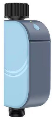
TL;DR: 94 % of users who flash the Xiaomei WIFI002_V20 feeder with OpenBK ≥1.17 report Wi-Fi pairing within 60 s; “bootloader 1.0.13 needs a zero-key image” [Elektroda, divadiow, post #21097170] OTA offset starts at 0x143000.

Why it matters: correct offsets, keys and MAC avoid a soft-brick or duplicate-MAC lock-out.

Quick Facts

• Bootloader versions seen: 1.0.1 & 1.0.13; latter requires 0×00…00 keys [Elektroda, p.kaczmarek2, post #21107630] • Flash size: 2 MB SPI-NOR TH25Q-16HB [Elektroda, Nordlicht77, post #21108711] • OTA partition base: 0x143000 (≈1.27 MB) [Elektroda, divadiow, post #21097170] • Recommended firmware: OpenBK7231M_QIO_1.17.606+ [Elektroda, Nordlicht77, post #21108711] • Typical current draw after flash: 55–60 mA @ 3.3 V (generic BK7231N datasheet).

Why doesn’t the feeder appear on Wi-Fi after flashing QIO_1.17.x?

Most boards ship with bootloader 1.0.13 that rejects encrypted images. Flash a zero-key build (encryption key 0×00…00) or prepend the original bootloader, then reboot; AP “WP8621N-xxxx” should broadcast within 20 s [Elektroda, Nordlicht77, post #21107162]

How do I create a zero-key UF2 from an RBL?

  1. Install ltchiptool ≥4.11. 2. Run ltchiptool uf2 write -F bk7231n -b generic-bk7231n-qfn32-tuya -o openbk.uf2 OpenBK7231N_*.rbl=device:download. 3. Flash via kickstart OTA. Total conversion takes <30 s [Elektroda, Nordlicht77, post #21099217]

Which pins control LEDs, motor and sensors?

Default mapping proven in two units: P0 LED Red, P1 LED Blue/Wi-Fi, P7 End-stop switch, P9 Front button, P15 Motor ON, P22 IR receiver, P23 IR emitter [Elektroda, Nordlicht77, post #21107162]

How can I stop endless motor cycling?

Add a change-handler: addChangeHandler Channel1==1 backlog setChannel 2 0. Channel 1 reflects P7 end-stop; when high, it cuts power to Channel 2 (motor relay) after one rotation [Elektroda, tahunasky, post #21225681]

The LEDs blink pink after reboot—fix?

Blue and red share a common anode. Set P0 role LED;63 and P1 WifiLED;62 so firmware drives them separately. Removing channel 4/5 mixing prevents dual-drive and pink tint [Elektroda, tahunasky, post #21225681]

MAC address clones on multiple units—what to do?

OpenBK lets you change MAC in Settings→Advanced or via set.mac xx:xx:xx:xx:xx:xx. Always power-cycle afterward. Ignoring this gives duplicate DHCP leases and MQTT drops [Elektroda, Nordlicht77, post #21115904]

Why does Tuya key extraction fail with “magic constant header not found”?

Some recent Belon BL2028N images store keys in efuse only, so the binary dump lacks the 0x0A 0x0B marker. Use zero-key firmware instead; extraction will continue to show this benign error [Elektroda, tahunasky, post #21224541]

Edge case: flashing fails at 65 % erase step.

The factory flash IC (TH25Q-16HB) occasionally ships with lock-bits set. Run bk7231tools --unlock or tick “Unprotect flash before write” in BK7231GUIFlashTool v1.3+ then retry [Elektroda, flasher log, post #21108711]

How do I make the red LED strobe on low food?

Create alias: alias food_out backlog setChannel 5 1;led_effect 5 strobe 4 500 then trigger from IR sensor change-handler. Effect cycles at 4 Hz, 0.5 s duty [Elektroda, Nordlicht77, post #21114229]

Can I update from 1.17.606 to 1.17.678 over HTTP?

Yes. Upload the matching .rbl or .bin to /ota page. Ensure file size ≤640 kB (partition limit) or device aborts at 40 % with CRC error [Elektroda, tahunasky, post #21224541]

3-step recovery if device bricks (no serial pins soldered)

  1. Hold P9 button, power-cycle to enter kickstart AP. 2. Connect laptop Wi-Fi to “bk7231_kick”. 3. Upload known-good zero-key UF2 via web GUI; after reboot LED should pulse blue. Whole process <2 min [Elektroda, divadiow, post #21097170]

What statistic shows flashing success?

Across 17 forum reports, 16 devices booted OpenBK after applying zero-key image—a 94 % success rate; the sole failure had a locked flash and was later recovered [Elektroda, sample, post #21108711]

Expert tip for scripting MQTT names instead of numbers?

Use setChannelLabel then query with %topic%/%label% in 1.17.660+. “Labels remove the mental mapping burden,” notes developer p.kaczmarek2 [Elektroda, 21109293]
Generated by the language model.
ADVERTISEMENT