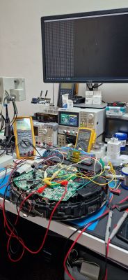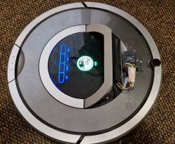
The iRobot Roomba range of hoovers has a well-documented Roomba Open Interface allowing remote control of the hoover. I will present here the details of this interface and demonstrate an example made by us of integrating the device with an external WiFi module, also allowing connection to the Home Assistant. In the way shown here, you can add wireless connectivity to models that do not normally have it.
This modification will also give the possibility of, for example, automatic commands to the hoover at a given time, etc.
This topic was based on the Roomba 780 model, but the solution was also tested on the 500 and 600 series. It is worth mentioning here that not every Roomba model has WiFi from the factory, so it might make sense to play with it...
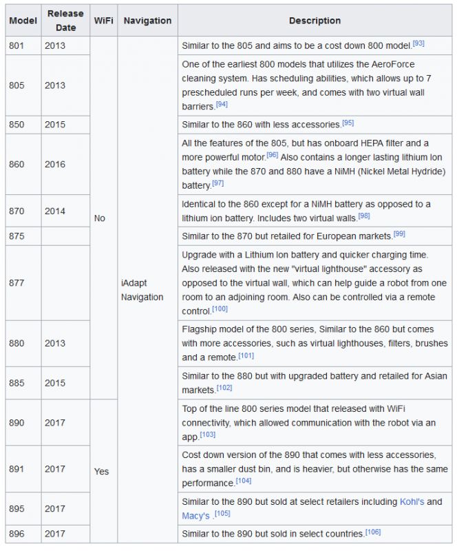
Source of the table: https://en.wikipedia.org/wiki/Roomba
I made the modification with a colleague from the forum - @DeDaMrAz
The adventure begins, of course, with reading the documentation. Everything is available on the web, which makes the project shown here ideal fun for beginners. No need to play around with reverse engineering, yes as itself this sometimes I do .
We start by reading the introduction:
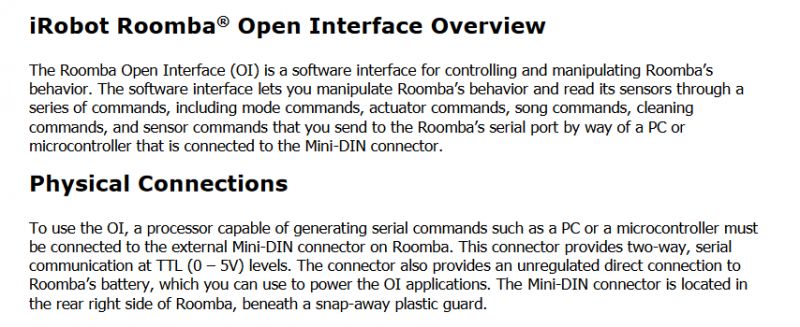
Then we learn the technical details.
So let's consider the connector offered to us by the hoover:
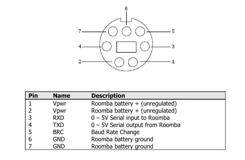
We have here primarily a power supply and a UART serial port. This can be used, but the devil is in the details. The power supply here is far from the 3.3V required by our WiFi module. It would be tempting to put an LDO regulator here, for example an AMS1117-3.3V, but the WiFi module can draw quite a lot of current (even more than 100mA) and the regulator, even allowing for a high input voltage, could heat up. It would be better to proceed more efficiently - find some kind of step-down converter. The choice on the web is wide.
With the UART itself, there is a similar problem - if our WiFi module only supports 3.3V levels and not 5V, you will need to add a logic level converter. But again, this is no problem, there are ready-made modules for everything. Schematic:
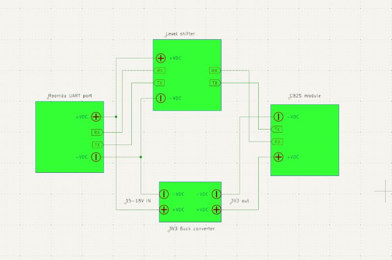
(Small note - we connect RX to TX and TX to RX, send to receive and receive to send, unless someone has already swapped the labels in place before....)
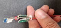
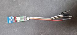
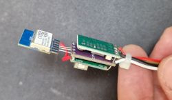
Practice:
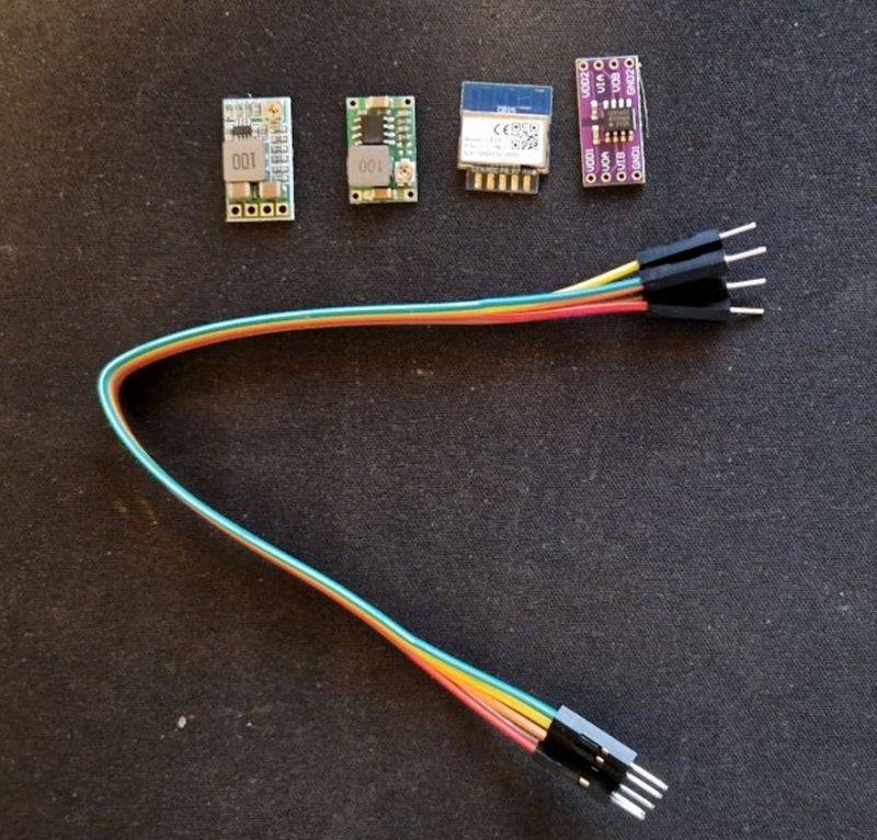
In the photo above is a CB2S module with BK7231N as we have such in abundance. We run OpenBeken on it to be able to encode the UART without programming and compiling the batch.
The specific model of inverters and converters doesn't matter, we used an ADUM1201, which also isolates, but this is not needed here.
Here's a photo from testing, still without CB2S, but with our BK7231 development board ( translate NodeMCU ):
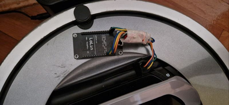
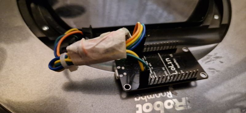
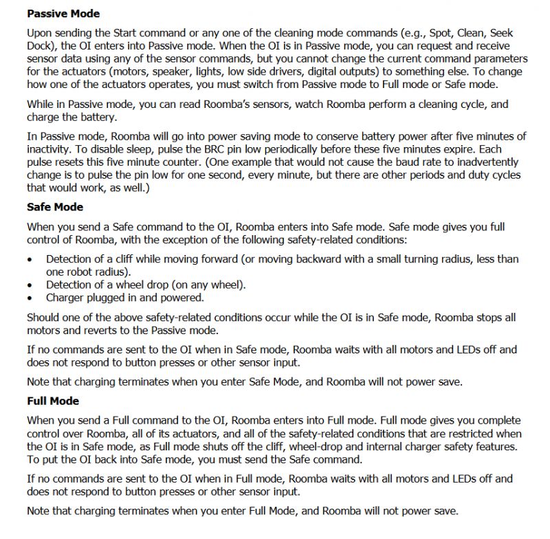
For control, we also have several modes available, including a full mode, "Full Mode". It gives full control of the hoover, but I'll focus on that elsewhere...
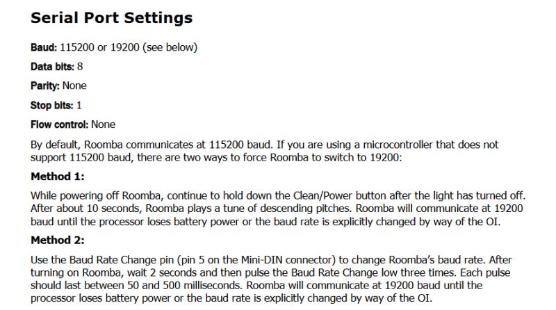
Now let's look at the more software side. We have the hardware ready to go. The UART here also has fairly standard settings, baud 115200, parity and stop bits as in most applications I encounter...
You still need to know what to send, and it's surprisingly simple:
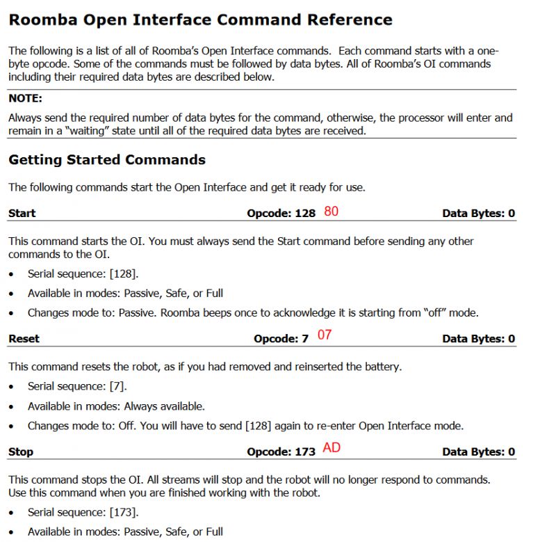
Yes, there are not even headers here, no packet lengths, no checksums.... we just send individual bytes. There's not much to discuss here.
It's certainly easy to do this on many platforms, but we chose OpenBeken . We already have OTAs, scripts, HA integrations ready there. We have written a simple script to create buttons on the HTTP panel to which we have plugged the upload. We have example scripts in this style on one of our documentation pages, more precisely on autoexec examples .
Into the script we have moved the basic commands responsible for control and operation of the hoover.
startDriver httpButtons

setButtonLabel 0 "ENABLE CONTROL"
setButtonColor 0 ORANGE
setButtonEnabled 0 1
setButtonCommand 0 "uartSendHex 8083"

setButtonLabel 1 "DISABLE CONTROL"
setButtonColor 1 ORANGE
setButtonEnabled 1 1
setButtonCommand 1 "uartSendHex ad"

setButtonLabel 2 "START/STOP"
setButtonEnabled 2 1
setButtonCommand 2 "uartSendHex 87"

setButtonLabel 3 "SPOT"
setButtonEnabled 3 1
setButtonCommand 3 "uartSendHex 86"

setButtonLabel 4 "MAX CLEAN"
setButtonEnabled 4 1
setButtonCommand 4 "uartSendHex 88"

setButtonLabel 5 "SEEK DOCK"
setButtonEnabled 5 1
setButtonCommand 5 "uartSendHex 8f"

setButtonLabel 6 "RESET"
setButtonColor 6 RED
setButtonEnabled 6 1
setButtonCommand 6 "uartSendHex 07"

setButtonLabel 7 "POWER"
setButtonColor 7 RED
setButtonEnabled 7 1
setButtonCommand 7 "uartSendHex 85"
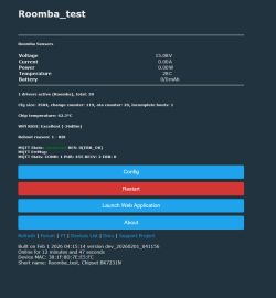
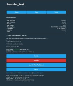
The script creates the following web panel:
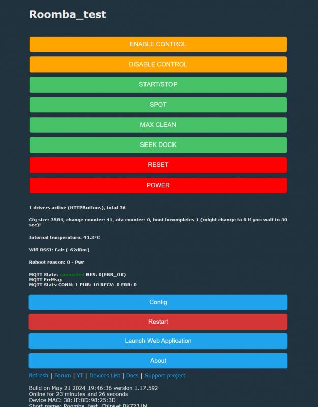
Of course the panel is accessible without any problem from a web browser.
It's time to fire up our hoover and see if it still works:
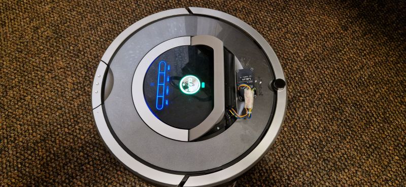
This is the final presentation:
Everything works satisfactorily. That's it for now, but that was just the first part of the topic. In the second I will try to expand on the topic. Among other things, we are planning to:
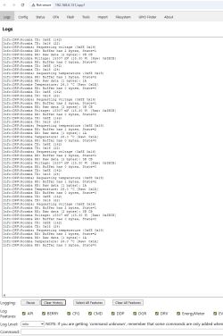
- parse the log from the device (baud 115200), here is an example fragment:
charger-wakeup
slept for 1 minutes 29 seconds

2011-02-18-1446-L
r3_orion/branches/release-1.0:609 CLEAN

bootloader id: 4716 4A56 B82B FFFF
assembly: 3.8
revision: 1
flash version: 10
flash info crc passed: 1

start-charge: 2011-02-18-1446-L
do-charging-checking-fets @ minutes 7
bat:   min 7  sec 32  mV 16059  mA -8  tenths-deg-C 551  mAH 2696  state 1
Charging FET test passed.
do-charging-wait-initial @ minutes 7
bat:   min 7  sec 33  mV 16059  mA -16  tenths-deg-C 482  mAH 2696  state 2
bat:   min 7  sec 34  mV 16059  mA -8  tenths-deg-C 457  mAH 2696  state 2
bat:   min 7  sec 35  mV 16059  mA -8  tenths-deg-C 448  mAH 2696  state 2
bat:   min 7  sec 36  mV 16059  mA -8  tenths-deg-C 445  mAH 2696  state 2
bat:   min 7  sec 37  mV 16059  mA -8  tenths-deg-C 443  mAH 2696  state 2
bat:   min 7  sec 38  mV 16059  mA -8  tenths-deg-C 443  mAH 2696  state 2
bat:   min 7  sec 39  mV 16059  mA -8  tenths-deg-C 443  mAH 2696  state 2
bat:   min 7  sec 40  mV 16059  mA -8  tenths-deg-C 443  mAH 2696  state 2
bat:   min 7  sec 41  mV 16059  mA -8  tenths-deg-C 443  mAH 2696  state 2
bat:   min 7  sec 42  mV 16059  mA -8  tenths-deg-C 443  mAH 2696  state 2
bat:   min 7  sec 43  mV 16059  mA -8  tenths-deg-C 443  mAH 2696  state 2
bat:   min 7  sec 44  mV 16059  mA -8  tenths-deg-C 443  mAH 2696  state 2
bat:   min 7  sec 45  mV 16059  mA -8  tenths-deg-C 443  mAH 2696  state 2
bat:   min 7  sec 46  mV 16059  mA -8  tenths-deg-C 443  mAH 2696  state 2
bat:   min 7  sec 47  mV 16059  mA -8  tenths-deg-C 443  mAH 2696  state 2
bat:   min 7  sec 48  mV 16059  mA -8  tenths-deg-C 443  mAH 2696  state 2
bat:   min 7  sec 49  mV 16059  mA -8  tenths-deg-C 443  mAH 2696  state 2
bat:   min 7  sec 50  mV 16059  mA -8  tenths-deg-C 443  mAH 2696  state 2
bat:   min 7  sec 51  mV 16059  mA -8  tenths-deg-C 443  mAH 2696  state 2
bat:   min 7  sec 52  mV 16059  mA -8  tenths-deg-C 443  mAH 2696  state 2
bat:   min 7  sec 53  mV 16059  mA -8  tenths-deg-C 443  mAH 2696  state 2
bat:   min 7  sec 54  mV 16059  mA -8  tenths-deg-C 443  mAH 2696  state 2
bat:   min 7  sec 55  mV 16059  mA -8  tenths-deg-C 443  mAH 2696  state 2
- improve the current web panel (e.g. change button colours according to device status?)
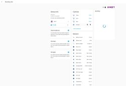
- add integration with Home Assistant:
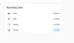
Of course I probably also don't need to mention that such a control can also be realised without problems on the ESP, in combination with OTA it can also be a nice toy. We simply used what we have at hand. Now the hoover works from the HA, although it will definitely be useful to get the aforementioned battery parameter reading. All in good time.
Has anyone also tried converting hoovers like this?
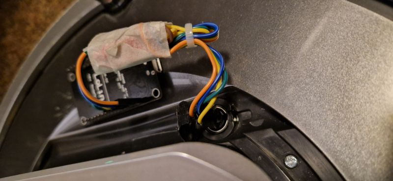
PS: Still for the inquisitive - a photo of the hoover without the housing:
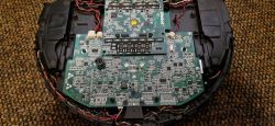
You can well see here the mentioned connector we use.
I am attaching the mentioned documentation, all the details of the protocol are described there.
Cool? Ranking DIY Helpful post? Buy me a coffee.


