The project I present below shows LED lighting ( but can also be classic ) switched on by a PIR sensor.
In my case, the inspiration was the notorious spilling of a sweet drink when I reached for it at night.
You're sleepy, it's a dark night, you want a drink, but it's hard to hit the glass in the dark, so it happened that all or part of the contents of the glass landed on the carpet instead of giving the thirsty person a drink.
Then, of course, the cleaning of such stains is both cumbersome and laborious.
The system presented here can also be used to light the way to the fountain or any other way to be travelled at night or in the dark (e.g. the cellar).
I should add that the device is very energy-efficient, as the power supply is switched on only briefly to maintain voltage on the supercapacitor and, of course, when lighting is activated via the PIR. For 99% of the time, the system draws practically no energy from the 230V mains.
To begin with, of course, the schematic diagram:
 .
.
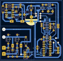
and the circuit board, as usual made by myself:
 .
.
It's worth saying a few words about the electronics themselves.
I don't have a problem with using processors where it makes sense, but in this case I preferred to use "more discrete" circuits, as using a processor in such a circuit wouldn't simplify anything circuit-wise, and you'd have to write some nonsense control software in addition.
So how does the circuit work?
Let's start with the fact that the circuit remains in standby for 100% of the time while being powered by the supercapacitor. When the voltage on the supercapacitor is sufficient, the circuit blocks the mains voltage through a circuit consisting of an optocoupler, an NMOS transistor and a bridge rectifier.
When the voltage on the supercapacitor drops below a designated level, the mains voltage is switched on and goes to a DC/DC converter or, more precisely, an AC/DC converter working as a DC/DC in this circuit. The inverter is an ordinary power supply from some mobile charger giving 12V and about 400mA at its output.
This voltage is used to power our LED strip and, when reduced to a value of about 2.7, charges our supercapacitor.
When the voltage on the supercapacitor reaches the required value, the mains voltage is disconnected from the circuit. The charging time of the supercapacitor is two to three minutes, and then the system operates for about six hours on the supercapacitor alone.
When movement activates the PIR detector, the mains voltage is switched on to power the lighting connected via the NMOS transistor, while the supercapacitor is charged.
Sensitivity and duration of illumination are adjusted by Pr-controls in the PIR detector (obviously of Chinese manufacture).
The mains voltage switching circuit is made on LM393 comparators and a CD4001 chip.
It is strikingly similar to the NE555 circuit, which gave me the idea to replace the LM393 and CD4001 tandem with some NE555 type circuit.
Unfortunately, the standard NE555 has improperly set switching thresholds and also draws considerable current, which is undesirable in such a device.
So I found Texas TLC555 circuits in my stash and reworked the circuit diagram for these. They have negligible resting current, small dimensions (SMD) and replace (after minor modification) a pair of LM393 and CD4001, saving space and standby current consumption.
Below is a diagram of the device with the TLC555 chip:
 .
.
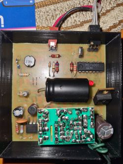
The finished circuit in the box looks like this:
 .
.
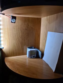
And then there's the same arrangement mounted on a bedside cabinet:
 .
.
I hope the layout is useful to someone and saves someone's carpet
I encourage esteemed colleagues to enrich the topic with their thoughts and/or ideas.
In my case, the inspiration was the notorious spilling of a sweet drink when I reached for it at night.
You're sleepy, it's a dark night, you want a drink, but it's hard to hit the glass in the dark, so it happened that all or part of the contents of the glass landed on the carpet instead of giving the thirsty person a drink.
Then, of course, the cleaning of such stains is both cumbersome and laborious.
The system presented here can also be used to light the way to the fountain or any other way to be travelled at night or in the dark (e.g. the cellar).
I should add that the device is very energy-efficient, as the power supply is switched on only briefly to maintain voltage on the supercapacitor and, of course, when lighting is activated via the PIR. For 99% of the time, the system draws practically no energy from the 230V mains.
To begin with, of course, the schematic diagram:
 .
.
and the circuit board, as usual made by myself:
 .
.
It's worth saying a few words about the electronics themselves.
I don't have a problem with using processors where it makes sense, but in this case I preferred to use "more discrete" circuits, as using a processor in such a circuit wouldn't simplify anything circuit-wise, and you'd have to write some nonsense control software in addition.
So how does the circuit work?
Let's start with the fact that the circuit remains in standby for 100% of the time while being powered by the supercapacitor. When the voltage on the supercapacitor is sufficient, the circuit blocks the mains voltage through a circuit consisting of an optocoupler, an NMOS transistor and a bridge rectifier.
When the voltage on the supercapacitor drops below a designated level, the mains voltage is switched on and goes to a DC/DC converter or, more precisely, an AC/DC converter working as a DC/DC in this circuit. The inverter is an ordinary power supply from some mobile charger giving 12V and about 400mA at its output.
This voltage is used to power our LED strip and, when reduced to a value of about 2.7, charges our supercapacitor.
When the voltage on the supercapacitor reaches the required value, the mains voltage is disconnected from the circuit. The charging time of the supercapacitor is two to three minutes, and then the system operates for about six hours on the supercapacitor alone.
When movement activates the PIR detector, the mains voltage is switched on to power the lighting connected via the NMOS transistor, while the supercapacitor is charged.
Sensitivity and duration of illumination are adjusted by Pr-controls in the PIR detector (obviously of Chinese manufacture).
The mains voltage switching circuit is made on LM393 comparators and a CD4001 chip.
It is strikingly similar to the NE555 circuit, which gave me the idea to replace the LM393 and CD4001 tandem with some NE555 type circuit.
Unfortunately, the standard NE555 has improperly set switching thresholds and also draws considerable current, which is undesirable in such a device.
So I found Texas TLC555 circuits in my stash and reworked the circuit diagram for these. They have negligible resting current, small dimensions (SMD) and replace (after minor modification) a pair of LM393 and CD4001, saving space and standby current consumption.
Below is a diagram of the device with the TLC555 chip:
 .
.
The finished circuit in the box looks like this:
 .
.
And then there's the same arrangement mounted on a bedside cabinet:
 .
.
I hope the layout is useful to someone and saves someone's carpet
I encourage esteemed colleagues to enrich the topic with their thoughts and/or ideas.
Moderated By Felini:.3.1.13. Publish posts that violate the spelling rules of the Polish language, are careless and incomprehensible.
The word "supercapacitor" does not exist in the Polish language.
Cool? Ranking DIY


