logo elektroda
logo elektroda
X
logo elektroda

Flashing OpenBL on Wi-Fi Smart Plug RMC021 (SM-028_V1.3, BL602)

C4ve 1635 20
ADVERTISEMENT
  • Helpful post
    #1 21224333
    C4ve
    Level 1  
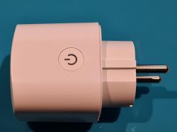
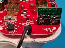
    Here a short look at the "Wi-Fi smart Plug Model: RMC021"

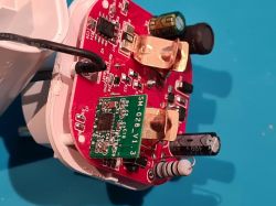
    It uses the SM-028V1.3 Module based on a Bouffalo Labs BL602.


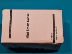
    External Pictures
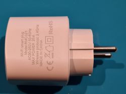
    White Wi-Fi smart plug Model: RMC021 with visible technical markings on a blue surface. White Wi-Fi smart plug with power button on a blue background. Box with the label Mini Smart Socket on a blue background.

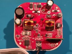
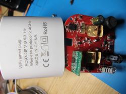
    Internal Pictures
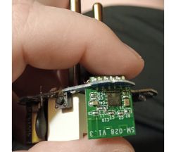
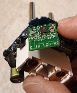
    Internal view of the SM-028_V1.3 module in a Wi-Fi plug. Interior of a red PCB of the Wi-Fi smart plug model RMC021. Close-up of the interior of a Wi-Fi smart plug model RMC021 showing electronic components.

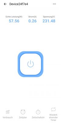
    Connected to eWeLink App
    Screenshot of an app interface displaying electricity consumption data of a device.
    Firmware Backup: See Attachments

    Now flashed with OpenBL
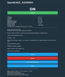
    OpenBL602 smart plug configuration screen with technical data.

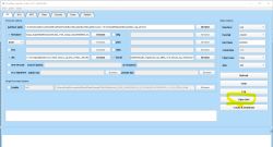
    It was flashed with Bouffalo Lab Dev Cube via a serial/Uart connection using a CH340 based USB to TTL converter with cables soldered to the 5 pins on the SM-028_v1.3 module. (3,3V, GND, RX, TX, BT)
    Sorry I took no pictures or screenshots while flashing.


    The device seems to be more or less similar to the Devices already documented:

    Brazil eWelink Smart Plug - divadiow
    Yet another Smart Socket 20A (but 16A) - flobuljeedom

    The only difference I have recognized so far is the Button connected to IO22 on this device.

    My Current Template:
    {
      "vendor": "Generic",
      "bDetailed": "0",
      "name": "Wi-Fi smart plug RMC021",
      "model": "RMC021",
      "chip": "BL602",
      "board": "TODO",
      "flags": "1024",
      "keywords": [
        "RMC021",
        "SM-028_V1.3",
        "BL602"
      ],
      "pins": {
        "2": "Rel;0",
        "3": "BL0937CF1;0",
        "14": "BL0937CF;0",
        "20": "LED_n;0",
        "21": "BL0937SEL;0",
        "22": "Btn;0"
      },
      "command": "backlog",
      "image": "https://obrazki.elektroda.pl/9547341300_1726165924.jpg",
      "wiki": "https://www.elektroda.com/rtvforum/topic4075409.html"
    }
  • ADVERTISEMENT
  • #2 21228756
    divadiow
    Level 35  
    cool. it seems there are a few RCM021 variants. These two are linked in the device list.

    https://www.elektroda.com/rtvforum/topic4044107.html#21014244
    https://www.elektroda.com/rtvforum/topic4040624.html

    Yours, with a red PCB, seems to be the same as https://www.elektroda.com/rtvforum/topic4065268.html but that has not found its way into the list.

    PR: https://github.com/OpenBekenIOT/webapp/commit/68a2cf393c65013b7cb8fbfce8fb37ec8bf32ef3
  • #3 21440109
    divadiow
    Level 35  
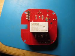
    I have this device too now though mine does not have the RMC021 print on the case.

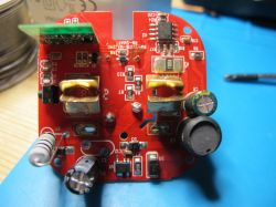
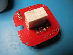
    Internal view of a WiFi smart plug with visible casing and PCB. Red electronic module with CNHZ HZ32-1A3S-LH1 relay.Close-up of a circuit board with various electronic components. Printed circuit board with CNHZ relay on red laminate.

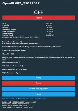
    User interface displaying energy values and settings of the OpenBL602 device.

    Boot log is
    Code: Text
    Log in, to see the code


    Added after 11 [minutes]:

    my device has the same firmware as yours <FWSWES-BLSWP1-SWP1-BL602L_v1.1.1>
  • ADVERTISEMENT
  • #4 21440150
    miegapele
    Level 15  
    3V relay and BP2525 in 3V configuration. Saves 3.3V regulator. I wonder why Chinese are not doing this more often.
  • #5 21602978
    blacksun2
    Level 8  
    divadiow wrote:

    Boot log is
    Code: Text
    Log in, to see the code


    How do you get this readable boot log output when the eWelink software is on the chip?
    I connected 3.3V, GND, RX1, and TX1 to my CP-2102. RX and TX are, of course, crossed.
    The 5V from the CP2101 is converted to 3.3V via a step-down converter.
    With RealTerm, for example, there is no readable output, regardless of whether it is ANSII or hex. And I've tried all baud rates.

    Thanks for your help
  • ADVERTISEMENT
  • #6 21602985
    divadiow
    Level 35  
    2000000 baud from same tx as flashing.
  • #7 21603137
    blacksun2
    Level 8  
    divadiow wrote:
    2000000 baud from same tx as flashing.


    Where is my mistake?


    Flashing OpenBL on Wi-Fi Smart Plug RMC021 (SM-028_V1.3, BL602)
  • #8 21603147
    divadiow
    Level 35  
    hmm. and you're able to read/write flash with OK with the same setup?

    I see you're powering from USB-TTL power which is almost certainly not enough for BL602, though I would have expected plain-text boot output until the point it initialises wifi, when it draws more power.
  • #9 21603162
    blacksun2
    Level 8  
    divadiow wrote:
    hmm. and you're able to read/write flash with OK with the same setup?

    yes
    divadiow wrote:

    I see you're powering from USB-TTL power which is almost certainly not enough for BL602, though I would have expected plain-text boot output until the point it initialises wifi, when it draws more power.

    But I do not use 3,3v from USB-TTL, I use 5V and use a stepdown-converter to 3,3v. I think 5V has much more power.
    And it is enough for WiFi coming up. I get back a ping within network. The blue led is shining.
  • ADVERTISEMENT
  • #10 21603166
    divadiow
    Level 35  
    hmm ok. same garbled output with putty and BLDC's own terminal?
  • #11 21603170
    blacksun2
    Level 8  
    divadiow wrote:
    hmm ok. same garbled output with putty and BLDC's own terminal?

    I tested putty and HTerm too.
    ASCII is correct?
    Which tool is Bouffalo's own terminal?
  • #13 21603181
    blacksun2
    Level 8  
    >>21603171
    the selections above are not necessary, right?
    you think there have to be an output at the white bottom field?
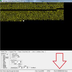
    there is only a message that port8 has opened, nothing else.
  • #14 21603190
    divadiow
    Level 35  
    selections don't matter. just open port. to be honest the other terminals shoud work ok. puzzling that you can flash OK but not see legible log

    blacksun2 wrote:
    you think there have to be an output at the white bottom field?

    yes

    Added after 1 [minutes]:

    you don't have boot pin pulled high still?

    Added after 2 [minutes]:

    have you tried swapping rx/tx anyway so it's RX->RX, TX->TX?
  • #15 21603237
    blacksun2
    Level 8  
    divadiow wrote:

    you don't have boot pin pulled high still?
    have you tried swapping rx/tx anyway so it's RX->RX, TX->TX?


    yes, I just made a backup of the flash, see attached file.
    my hardware is working definitely and the RX-TX-Combination is working.
    and yes, after making the backup, I unattached RT
  • #16 21603240
    divadiow
    Level 35  
    I'm not really sure what the issue is to be honest.

    Your device is a BL602L10 with 1mb flash?

    Added after 7 [minutes]:

    how come you dumped with blflash?
  • #17 21603441
    blacksun2
    Level 8  
    divadiow wrote:

    Your device is a BL602L10 with 1mb flash?
    how come you dumped with blflash?


    why not using blflash? It has done it's job.

    It's difficult to take a photo.
    I'd say the end result isn't L10, but L20.


    Flashing OpenBL on Wi-Fi Smart Plug RMC021 (SM-028_V1.3, BL602)
    Flashing OpenBL on Wi-Fi Smart Plug RMC021 (SM-028_V1.3, BL602)

    Since recording the boot process didn't work, I now have a problem with the PINs.
    Do you think you could help me with that?

    I've tried all 9 socket variants listed in the device overview in the filter on the BL602. None of them make the button work.
  • #18 21603525
    divadiow
    Level 35  
    blacksun2 wrote:
    why not using blflash? It has done it's job.

    yeh, maybe it's OK. I just seem to remember it being flaky, but that was when I first started my adventures. L20 is a 2mb chip so your backup only seems to be half the flash.

    Flashing OpenBL on Wi-Fi Smart Plug RMC021 (SM-028_V1.3, BL602)

    If none of the existing device templates work then it'll be a case of trial/error, visually tracing from contacts on module and continuity checking with a multimeter to determine the corrects pins.

    GPIO Dr can help greatly https://www.elektroda.com/news/news3976371.html
    the limited number of contacts on SM-028_V1.3 module already limit your options for what the assignments can be.


    Flashing OpenBL on Wi-Fi Smart Plug RMC021 (SM-028_V1.3, BL602)
  • #19 21603784
    blacksun2
    Level 8  
    [postid:034158fc92][/postid:034158fc92]
    big thanks for your picture.
    According to this picture, is this correct?

    which one is BL0937CF1, which is BL0937CF, which is BL0937SEL

    Where do you think the button leads?

    Flashing OpenBL on Wi-Fi Smart Plug RMC021 (SM-028_V1.3, BL602)
    Flashing OpenBL on Wi-Fi Smart Plug RMC021 (SM-028_V1.3, BL602)

    Now that OBK is flashed, can it actually display the actual memory size? I'm wondering whether the chip has 1MB or 2MB of memory.
  • #20 21604272
    divadiow
    Level 35  
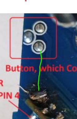
    maybe this trace to that module pad?

    Flashing OpenBL on Wi-Fi Smart Plug RMC021 (SM-028_V1.3, BL602)

    you can also set btn for unknown gpios remaining on module then push button to see which registers in the web app log console. If you get several button/long push button entries for different gpios then that will be something else - possibly one of the 3 BL0937 legs.
  • #21 21604683
    blacksun2
    Level 8  
    I think I'm too dumb for the "GPIO Doctor" in the web app. I still don't understand how it works, with the different buttons and when I should press which one.
    I also don't understand whether you have to fill in something in the dropdown when searching, or in the Channel field.

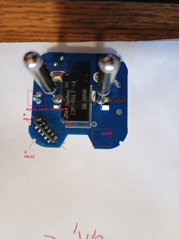
    I've now figured it out under "Config" by simply trying it out. The button is P4. That's very unusual, since I haven't found a single socket in the device overview that uses P4.

    Can you explain two more things to me?
    a) The BL0937 always uses three GPIOs. How do I find out if BL0937CF, BL0937CF1, and BL0937SEL are assigned to the correct Pxx in OBK?
    I'm asking because with buttons, LEDs, and relays, you can see or hear it. There's only on or off.

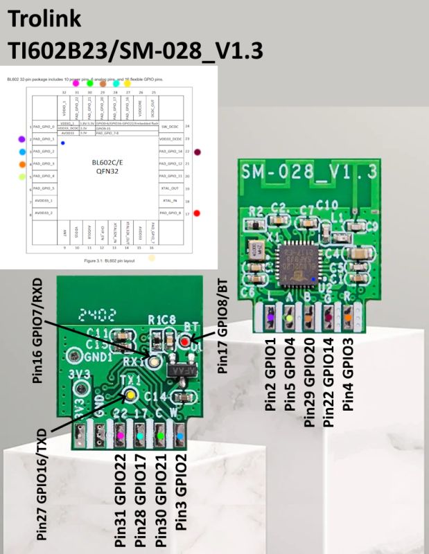
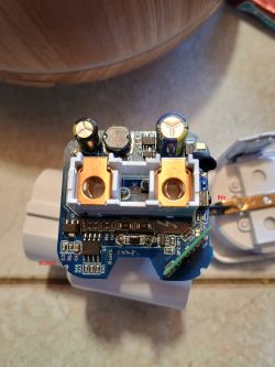
    b) If you look at your pinout diagram and then my two photos, you can see the three tracks and which connections on the SM-028_V1.3 they lead to.
    Would you also say that they lead to the letters G, R, and C?
    In your diagram for the SM-028-V1.3, are the pins described there the Pxx in OBK?
    In OBK for the BL602 chip, there are only P0 to P23. How is it possible that there is a pin 27 to pin 31 on your diagram? That's not possible.

Topic summary

The Wi-Fi Smart Plug Model RMC021 utilizes the SM-028V1.3 module based on the Bouffalo Labs BL602 chip. The device was successfully flashed with OpenBL firmware using the Bouffalo Lab Dev Cube via a serial UART connection, employing a CH340 USB to TTL converter connected to the module's 3.3V, GND, RX, TX, and BT pins. Multiple variants of the RMC021 exist, including versions with different PCB colors and markings. Boot logs confirm the BL602 chip running a RISC-V core with the release_bl_iot_sdk_1.6.34 firmware. The device features a 3V relay and a BP2525 power management IC configured for 3V operation, eliminating the need for a 3.3V regulator. Community references include device lists and firmware pull requests related to OpenBekenIOT support for these smart plugs.
Summary generated by the language model.
ADVERTISEMENT