FAQ
TL;DR: 16 kHz factory PWM was logged; "2 kHz + 8/4‑bit is the only usable output" on custom WLED, per builder. This ESP32‑C3 SP530E needs efuse‑aware flashing, custom WLED for GPIO19, and OpenESP lacks SPI today. [Elektroda, divadiow, post #21230102]
Why it matters: This FAQ helps makers fix flashing, PWM, and SPI issues on the SP530E when using OpenESP/OpenBeken or WLED, fast.
Quick facts
- MCU: ESP32‑C3 (rev v0.3), 4 MB embedded flash, 40 MHz crystal, Wi‑Fi + BLE. [Elektroda, divadiow, post #21230102]
- Power stage: 74HC245D level shifts MCU A→B into MOSFET gates; five PWM channels plus a separate SPI data path. [Elektroda, divadiow, post #21230102]
- Security state seen: Flash Encryption enabled → disabled after burning efuses; SPI_BOOT_CRYPT_CNT moved 0x1 → 0x3. [Elektroda, divadiow, post #21230102]
- PWM notes: Factory 16 kHz; a custom WLED build ran 2 kHz with 8/4‑bit for usable analog output. [Elektroda, divadiow, post #21230102]
- WLED tip: GPIO12–19 require a custom build with USB_CDC disabled; GPIO19 then works for WS2812. [Elektroda, divadiow, post #21230102]
Quick Facts
- MCU: ESP32‑C3 (rev v0.3), 4 MB embedded flash, 40 MHz crystal, Wi‑Fi + BLE. [Elektroda, divadiow, post #21230102]
- Power stage: 74HC245D level shifts MCU A→B into MOSFET gates; five PWM channels plus a separate SPI data path. [Elektroda, divadiow, post #21230102]
- Security state seen: Flash Encryption enabled → disabled after burning efuses; SPI_BOOT_CRYPT_CNT moved 0x1 → 0x3. [Elektroda, divadiow, post #21230102]
- PWM notes: Factory 16 kHz; a custom WLED build ran 2 kHz with 8/4‑bit for usable analog output. [Elektroda, divadiow, post #21230102]
- WLED tip: GPIO12–19 require a custom build with USB_CDC disabled; GPIO19 then works for WS2812. [Elektroda, divadiow, post #21230102]
What is the SP530E 5CH PWM+SPI LED controller, in short?
It is a BTF Lighting–sold board using an ESP32‑C3 with five PWM MOSFET channels and an SPI pixel output. The MCU drives a 74HC245D level shifter configured A→B, then gate resistors into MOSFETs. It exposes on‑board status LEDs and UART for debugging. Factory firmware ran PWM at 16 kHz, and the board level‑shifts the digital data line to 5 V. [Elektroda, divadiow, post #21230102]
Can the five PWM channels and the SPI output be controlled independently?
The attached manual and user review indicate no restriction on independent control. "I don't think I see anything that says they can't be controlled independently." Treat PWM (e.g., RGBCW) and SPI strips as separate outputs in the app when available. Hardware uses separate paths: five MOSFET PWM channels and one SPI data path through the 74HC245D. [Elektroda, divadiow, post #21231424]
How do I enter bootloader mode on SP530E and run esptool?
Use this 3‑step:
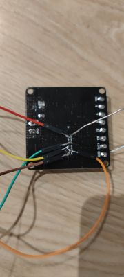
- Solder the rear pads and pull IO9 low to enter download mode.
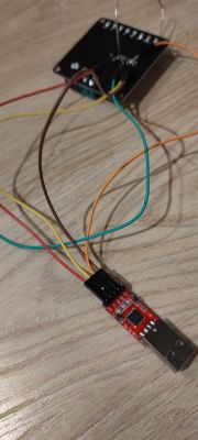
- Connect UART to GPIO20/21 (RX/TX) and power the board.
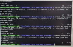
- Run esptool to query or flash (e.g., get_security_info, flash_id, write_flash).
This board identified as ESP32‑C3 with 4 MB embedded flash and 40 MHz crystal in logs. [Elektroda, divadiow, post #21230102]
How do I check and change Flash Encryption/Secure Boot status on this board?
Check with: esptool get_security_info. The sample unit showed Flash Encryption enabled and SPI_BOOT_CRYPT_CNT 0x1. The user then burned efuses DIS_DOWNLOAD_MANUAL_ENCRYPT and SPI_BOOT_CRYPT_CNT, after which Flash Encryption read disabled and the counter was 0x3. Treat efuse changes as permanent and plan backups first. [Elektroda, divadiow, post #21230102]
Can I restore the factory firmware after burning those efuses?
The user warned that returning to factory may not be possible after burning DIS_DOWNLOAD_MANUAL_ENCRYPT and SPI_BOOT_CRYPT_CNT. Always check current security with get_security_info and keep full backups. Without original encrypted images matching the original security state, the vendor firmware may not boot. [Elektroda, divadiow, post #21332044]
What esptool write_flash command and offsets worked for WLED on ESP32‑C3 4 MB?
Example used: esptool.py -b 115200 write_flash 0x0 C3_bootloader.bin 0x8000 C3_partitions_4M.bin 0x10000 WLED_0.15.0-b7_ESP32C3_4MB.bin. This targeted bootloader at 0x0, partitions at 0x8000, and app at 0x10000. The session identified an ESP32‑C3 revision v0.4 with 4 MB embedded flash, and verified hashes after flashing. [Elektroda, vo1xabrad, post #21331970]
How do I know WLED actually booted on the SP530E?
You should see the WLED setup AP broadcasting. If nothing appears, open a serial terminal on UART TX and capture boot logs. The author expects the AP to show if the firmware booted correctly, so logs help confirm or diagnose. [Elektroda, divadiow, post #21333651]
Why does the WS2812 data line stay high or not drive my strip?
On SP530E, the 74HC245D level‑shifts MCU outputs, and not all pins reach the driver. GPIO12–19 are restricted in stock WLED builds on C3. Use a custom build that disables USB_CDC, then drive data on GPIO19. The author saw digital animations work after unlocking IO19; without it, the data output idled high. [Elektroda, divadiow, post #21230102]
What GPIO mapping works for PWM and on‑board parts?
Observed map: 0 BlueLED, 1 GreenLED, 3 Button, 4 WW, 5 CW, 6 G, 7 B, 10 R, 19 Data (WS2812). UART is GPIO20/21 (RX/TX). GPIO0/1 also drive board LEDs. The MCU connects to 74HC245D for PWM channels through gate resistors to MOSFETs. [Elektroda, divadiow, post #21230102]
Can OpenESP/OpenBeken change PWM frequency on ESP32‑C3 right now?
OpenESP uses ESP‑IDF’s LEDC for PWM, which supports frequency control. However, the current HAL did not call ledc_set_freq in the referenced code, so the user’s pwmfrequency command had no effect yet. "LEDC is used for PWM." [Elektroda, p.kaczmarek2, post #21231588]
Is SPI LED output supported in OpenESP on this device yet?
Not yet. The user confirmed no OpenESP support for SPI on this SP530E at the time of testing. PWM also showed issues pending LEDC implementation updates in the ESP HAL. [Elektroda, divadiow, post #21230102]
What PWM frequencies actually worked on this board?
Factory firmware drove PWM at 16 kHz and looked clean. A WLED contributor hardcoded 2 kHz with 8/4‑bit to get usable analog output on this SP530E. Without that, their analog LEDs were dim or unstable. This board behaves unusually under default WLED settings. [Elektroda, divadiow, post #21230102]
I see Wi‑Fi PHY calibration warnings after flashing—normal?
Logs showed: "failed to load RF calibration data (0x1102), falling back to full calibration," followed by saving new calibration and AP start at 192.168.4.1. This appeared during first Wi‑Fi bring‑up after flashing. It did not prevent AP mode. [Elektroda, divadiow, post #21230102]
How do I unlock GPIO12–19 for WLED on ESP32‑C3?
Use a custom WLED build that disables USB_CDC for ESP32‑C3. The thread links a community compiler. After that, IO19 produced working WS2812 animations on the SP530E. Default builds do not expose those pins. [Elektroda, divadiow, post #21230102]
Any quick checks to confirm OpenESP/OpenBeken is alive on SP530E?
Check on‑board LEDs on IO0/1, which light under OpenESP. Watch the serial boot log for AP startup and DHCP server at 192.168.4.1. The log also prints the device MAC and memory stats during boot. [Elektroda, divadiow, post #21230102]