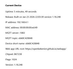
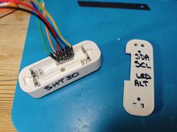
I have a few TH01 generic Tuya battery-powered temperature/hygrometer sensors lying in a box and although they were fun to analyse and flash to OBK, I don't have a real use for them.
Two of them have CHT8310 temperature/humidity sensors, as opposed to the AHT20 and AHT30s in some of the others. I thought it'd be much more useful to have a CHT8310 sensor on its own for testing with other OpenBeken platforms - OpenBL, OpenESP, OpenW800, OpenLN etc. I have separate AHTs, but all the CHT8310s are in Beken devices.
This TH01 is the same as this thread with CBU module https://www.elektroda.com/rtvforum/topic4019974.html. No TuyaMCU in the way.
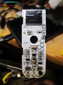
I started by removing the CBU (to be kept of course) with a load of flux and my 858D hot air gun.
Now that the RX, TX and CEN test pads are of no use, could I use them for SDA, SCL and the Alert pins of the sensor? The test holes would also give me something solid to solder wires into.
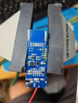
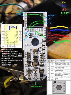
There was continuity from the SCL and SDA pins of the sensor straight through to the CBU pads. Only the alert pin was indirect via resistor R7, which was going to stay in place. It seemed like I could link pads directly as follows:
SCL P20 -> CEN
SDA P22 -> RX1
ALERT P7 -> TX1
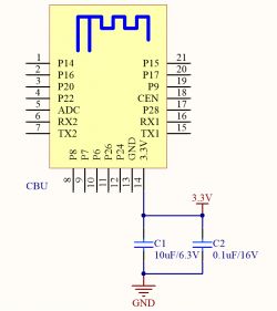
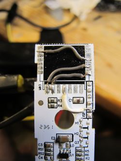
To illustrate, I made this:
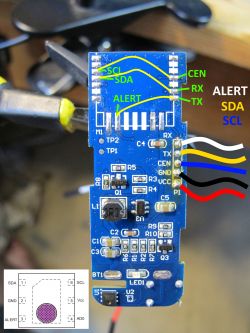
Then realised that with solder and wires:
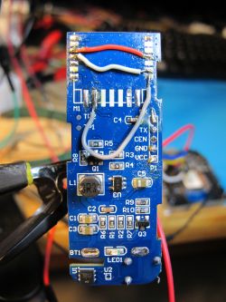
I don't know why I made the grey so long.
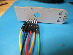
There was continuity right through from the legs of the CHT, and R7 for alert pin, to the ends of the jumper wires.
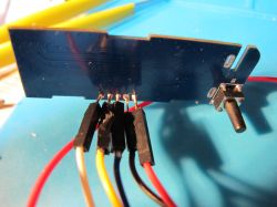
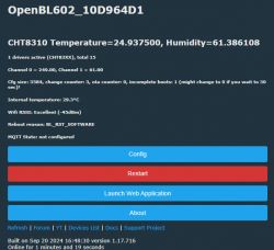
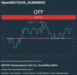
The moment of truth with a test on a CB3S/BK7231N
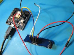
P7-> SDA
P8 -> SCL

😁
And with SoftSCL/SoftSDA assigned P7/P8 and these commands
we get the i2c address for this Sensylink sensor
Time to make some wonky holes in the casing and clean up the flux with IPA.
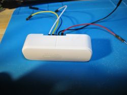
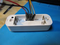
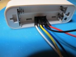
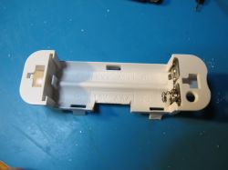
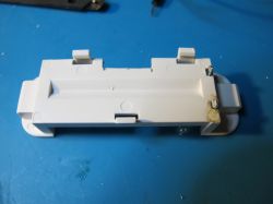
and some ugly pen markings because I don't have a fine-point permanent marker or a label printer
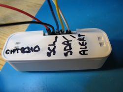
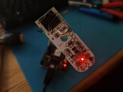
Maybe I could have made use of the LED and button, but I'm OK with it being what it is right now.
To do:
-tidy grey wire and soldering
-test alert pin function
-test CHT driver on other platforms
Two of them have CHT8310 temperature/humidity sensors, as opposed to the AHT20 and AHT30s in some of the others. I thought it'd be much more useful to have a CHT8310 sensor on its own for testing with other OpenBeken platforms - OpenBL, OpenESP, OpenW800, OpenLN etc. I have separate AHTs, but all the CHT8310s are in Beken devices.
This TH01 is the same as this thread with CBU module https://www.elektroda.com/rtvforum/topic4019974.html. No TuyaMCU in the way.
I started by removing the CBU (to be kept of course) with a load of flux and my 858D hot air gun.
Now that the RX, TX and CEN test pads are of no use, could I use them for SDA, SCL and the Alert pins of the sensor? The test holes would also give me something solid to solder wires into.

There was continuity from the SCL and SDA pins of the sensor straight through to the CBU pads. Only the alert pin was indirect via resistor R7, which was going to stay in place. It seemed like I could link pads directly as follows:
SCL P20 -> CEN
SDA P22 -> RX1
ALERT P7 -> TX1

To illustrate, I made this:

Then realised that with solder and wires:

I don't know why I made the grey so long.
There was continuity right through from the legs of the CHT, and R7 for alert pin, to the ends of the jumper wires.

The moment of truth with a test on a CB3S/BK7231N

P7-> SDA
P8 -> SCL

😁
And with SoftSCL/SoftSDA assigned P7/P8 and these commands
Code: Text
we get the i2c address for this Sensylink sensor
Code: Text
Time to make some wonky holes in the casing and clean up the flux with IPA.


and some ugly pen markings because I don't have a fine-point permanent marker or a label printer

Maybe I could have made use of the LED and button, but I'm OK with it being what it is right now.
To do:
-tidy grey wire and soldering
-test alert pin function
-test CHT driver on other platforms


