logo elektroda
logo elektroda
X
logo elektroda

PC321-W-TY 3 Phase Power Meter: OpenBeken Compatibility with BK7231N MCU?

hojnikb 1953 23
ADVERTISEMENT
  • #1 21264396
    hojnikb
    Level 11  
    So I got this 3 phase energy meter.

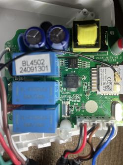
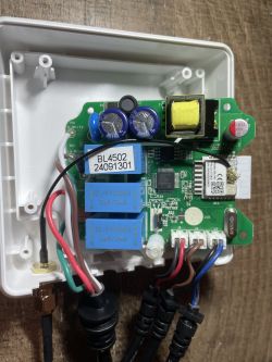
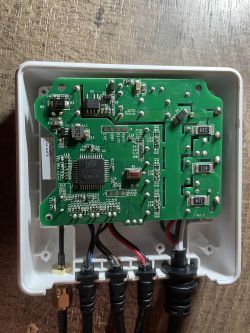
    It appears to be based around CBU-IPEX, so BK7231N MCU. Energy monitoring chip is ATT7022EU and GD32E230, some sort of STM32 clone (doing what exactly??) and 25VQ32BSIG 4MB SPI memory chip (for BK7231N maybe?).

    Strange little device. Any ideas if this could be made compatible with OpenBeken?

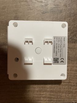
    Interior view of a 3-phase energy meter showing electronic components. Interior view of a 3-phase energy meter with visible electronic components. View of the interior of a 3-phase energy meter with visible electronic components. Close-up of the internal circuit board of a 3-phase energy meter with visible electronic components. Back of a 3-phase energy meter with manufacturer label.
  • ADVERTISEMENT
  • #2 21264823
    p.kaczmarek2
    Moderator Smart Home
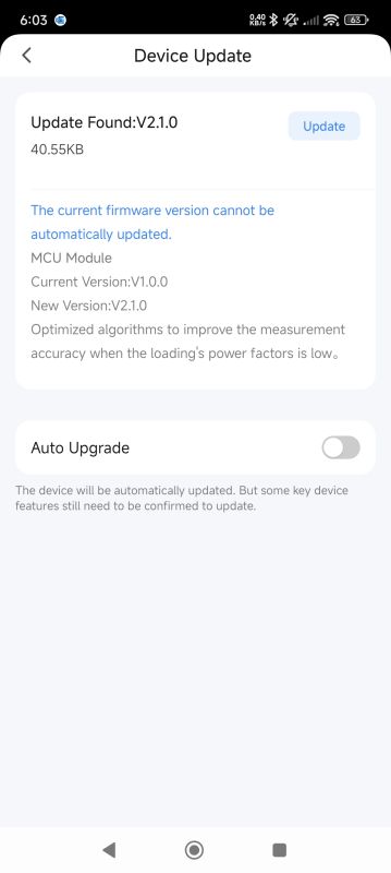
    Well, isn't it a TuyaMCU device? TuyaMCU is more or less compatible with OBK, once you know the meaning of dpIDs...
    https://www.elektroda.com/rtvforum/topic4038151.html
    Helpful post? Buy me a coffee.
  • #3 21265112
    hojnikb
    Level 11  
    p.kaczmarek2 wrote:
    Well, isn't it a TuyaMCU device? TuyaMCU is more or less compatible with OBK, once you know the meaning of dpIDs...
    https://www.elektroda.com/rtvforum/topic4038151.html


    I figured that mcu itself should be compatible, but I'm not too sure about the actual functionality of power measurement. as I haven't seen any profiles for this specific device.

    I will check this thread, if I can figure it out.
  • ADVERTISEMENT
  • #5 21265237
    hojnikb
    Level 11  
    p.kaczmarek2 wrote:
    Can you share 2MB flash backup?

    Absolutely, I will hook up the device to serial and try to backup.
  • #6 21266852
    hojnikb
    Level 11  
    p.kaczmarek2 wrote:
    Can you share 2MB flash backup?


    I'm trying to backup the device using easy uart flasher, but with no success. I've directly soldered TX1 and RX1 to my usb-serial and did CEN pin short to ground, but unfortunately, it does not get detected by utility.

    Am I missing something?

    Added after 44 [minutes]:

    Perhaps there is something connected to the TX1/RX1 pins? I will attempt to desolder the module.

    Interestingly, there are two sets of rx/tx pin headers on the motherboard.

    Added after 20 [minutes]:

    Yep, this was exactly the culprit. After desoldering the module, reading was easy.

    Attached is dump of the flash. PC321-W-TY... DUMP .bin Download (2 MB)
  • Helpful post
    #7 21267501
    divadiow
    Level 34  
    some extra info.
    boot log (from dev board flash of dump - ie MCU of original device missing)

    Code: Text
    Log in, to see the code


    and the extracted info from storage area in binary

    Code: JSON
    Log in, to see the code
  • #8 21269556
    hojnikb
    Level 11  
    I played around with the device a bit more.

    JSON @divadiow provided was very helpful for mapping at least some of the IDs

    This is what I was able to map:

    //Voltage L1
    setChannelType 1 Voltage_div10
    linkTuyaMCUOutputToChannel 101 val 1
    
    //Voltage L2
    setChannelType 2 Voltage_div10
    linkTuyaMCUOutputToChannel 111 val 2
    
    //Voltage L3
    setChannelType 3 Voltage_div10
    linkTuyaMCUOutputToChannel 121 val 3
    
    //Current L1
    setChannelType 7 Current_div1000
    linkTuyaMCUOutputToChannel 102 val 7
    
    //Current L2
    setChannelType 8 Current_div1000
    linkTuyaMCUOutputToChannel 112 val 8
    
    //Current L3
    setChannelType 9 Current_div1000
    linkTuyaMCUOutputToChannel 122 val 9
    
    //Power L1
    setChannelType 10 Power
    linkTuyaMCUOutputToChannel 103 val 10
    
    //Power L2
    setChannelType 11 Power
    linkTuyaMCUOutputToChannel 113 val 11
    
    //Power L3
    setChannelType 12 Power
    linkTuyaMCUOutputToChannel 123 val 12
    
    //Power factor L1
    setChannelType 4 PowerFactor_div100
    linkTuyaMCUOutputToChannel 104 val 4
    
    //Power factor L2
    setChannelType 5 PowerFactor_div100
    linkTuyaMCUOutputToChannel 114 val 5
    
    //Power factor L3
    setChannelType 6 PowerFactor_div100
    linkTuyaMCUOutputToChannel 124 val 6
    
    //Combined power
    setChannelType 13 Power
    linkTuyaMCUOutputToChannel 133 val 13


    The values that get spit out make some sort of sense (if my kill-o-watt was to be believed). Not too sure what values represent active or reactive power (would need a power meter capable of displaying these). I was also not able to find frequency value either for each phase or at least all of them.


    And to my understanding IDs 101-107 (and 111-117, 121-127) represent each phase and everything 131 and after must either be combined values or single values for the whole system, but I was not quite able to map all of them as of yet.
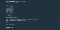
    Display of OpenBK7231N data showing voltages, power factors, currents, and powers for different phases.

    Added after 24 [minutes]:

    dpID 135 might represent frequency, but channelTypes doesn't seem to have a frequency without a divider (just divider 10 or 100).

    Added after 1 [hours] 37 [minutes]:

    Played around a bit more;

    dpID 132 could be combined reactive power. dpID 136 seems to be a value around 400 (jumping up and down a few points) and is not affected by removing current clamp. Not to sure about this one.

    All other values i exposed are sitting at zero currently. Might be my testing methodology, as i'm using a single phase and combining the voltages and putting current clamp on only one phase (so all phases should have equal power/current etc).
  • #9 21273326
    hojnikb
    Level 11  
    Here's my final config i was able to come up with;

    There's still some missing data like reactive power, but for now it should do as a basic power meter.

    // Start TuyaMCu driver
    startDriver TuyaMCU
    // set TuyaMCU baud rate
    tuyaMcu_setBaudRate 115200
    // set TuyaMCU default wifi state 0x04, which means "paired",
    // because some TuyaMCU MCUs will not report all data
    // unless they think they are connected to cloud
    tuyaMcu_defWiFiState 4
    
    //Voltage L1
    setChannelType 1 Voltage_div10
    linkTuyaMCUOutputToChannel 101 val 1
    
    //Voltage L2
    setChannelType 2 Voltage_div10
    linkTuyaMCUOutputToChannel 111 val 2
    
    //Voltage L3
    setChannelType 3 Voltage_div10
    linkTuyaMCUOutputToChannel 121 val 3
    
    //Current L1
    setChannelType 7 Current_div1000
    linkTuyaMCUOutputToChannel 102 val 7
    
    //Current L2
    setChannelType 8 Current_div1000
    linkTuyaMCUOutputToChannel 112 val 8
    
    //Current L3
    setChannelType 9 Current_div1000
    linkTuyaMCUOutputToChannel 122 val 9
    
    //Power L1
    setChannelType 10 Power
    linkTuyaMCUOutputToChannel 103 val 10
    
    //Power L2
    setChannelType 11 Power
    linkTuyaMCUOutputToChannel 113 val 11
    
    //Power L3
    setChannelType 12 Power
    linkTuyaMCUOutputToChannel 123 val 12
    
    //Power factor L1
    setChannelType 4 PowerFactor_div100
    linkTuyaMCUOutputToChannel 104 val 4
    
    //Power factor L2
    setChannelType 5 PowerFactor_div100
    linkTuyaMCUOutputToChannel 114 val 5
    
    //Power factor L3
    setChannelType 6 PowerFactor_div100
    linkTuyaMCUOutputToChannel 124 val 6
    
    //Combined power
    setChannelType 13 Power
    linkTuyaMCUOutputToChannel 133 val 13
    
    //Frequency
    setChannelType 14 ReadOnly
    linkTuyaMCUOutputToChannel 135 val 14
    
    
    //kWh Total
    setChannelType 18 EnergyTotal_kWh_div100	
    linkTuyaMCUOutputToChannel 131 val 18
    
    
  • #10 21305696
    ipasitt
    Level 2  
    >>21269556
    Hi, I also have this similar unit. Would you please advise how I can flash the CBU-IPEX chip? I tried BK7321flasher but failed, and tuya-cloudcutter was unsuccessful too.
  • #11 21305803
    p.kaczmarek2
    Moderator Smart Home
    You need to disconnect UART connection between WiFi module and the MCU in order to flash TuyaMCU device. It's been mentioned in our TuyaMCU guide here:
    TuyaMCU flashing, setup and configuration guide - configure dpIDs for Home Assistant
    Helpful post? Buy me a coffee.
  • ADVERTISEMENT
  • #12 21308059
    hojnikb
    Level 11  
    p.kaczmarek2 wrote:
    You need to disconnect UART connection between WiFi module and the MCU in order to flash TuyaMCU device. It's been mentioned in our TuyaMCU guide here:
    TuyaMCU flashing, setup and configuration guide - configure dpIDs for Home Assistant


    Hi!

    Would you know why the device is rebooting itself a few times a day? That itself wouldn't be a problem, but the totalKWh goes to zero for that time and messes up daily calculation.
  • #13 21312184
    hojnikb
    Level 11  
    it appears that the reason is watchdog reset --- why would a device like this be freezing multiple times a day?
  • #14 21312204
    p.kaczmarek2
    Moderator Smart Home
    Wait, do you mean OBK or TuyaMCU totalKWh ? It's not kept between restarts?
    Helpful post? Buy me a coffee.
  • ADVERTISEMENT
  • #15 21312214
    hojnikb
    Level 11  
    p.kaczmarek2 wrote:
    Wait, do you mean OBK or TuyaMCU totalKWh ? It's not kept between restarts?


    I'm assuming tuyaMCU, as this is a tuya based device. The value from the channel, that monitors totalKWh goes to zero after a reboot and comes back to real value after 5-10 seconds after boot.
  • #16 21416764
    crg1darkspr1te
    Level 8  
    I recently got one of these units for testing and I was able to dump the GD32E230 chip, I have provided that dump along with data sheets and SVD file for the same.
    Anyone wishing to restore one of these units to full factory or replacing the GD32E230 chip can use the files enclosed.
    I will start reverse engineering over the weekend I think. Already started
    Some info:
    Bootloader 0x08000000 - 0x08003fff
    App program 0x08004000 - 0x0800dfff

    command checking 0x08008390
    app strings 0x0800d774


    darkspr1te
  • #17 21417409
    crg1darkspr1te
    Level 8  
    So I have identified a lot of the routines so far, bootloader for app start, updating app area, controlling boot order/failure modes.
    The SPI flash is used by the App program to store the updates for the benken chip as well as a copy of the App program and crc checks
    MCU updates can be done in two ways, storing on SPI flash and reboot checks flash for update (crc checks involved) or via direct wifi connection (data is saved in sram and flash, MCU is rebooted and benken sends the update to bootloader which stores it in flash, checks crc and then flashes APP section.

    in app mode the spi flash is used to store logs etc, updates for mcu and benken can be sent via the update command 0x10 (spi then update via mcu bootloader ) & 0xb (mcu bootloader ) either mode 0x1 (spi mcu app area benken) - 0x2 (direct - mcu app area only )
    full command list support for v2.0.2
    
    00 heartbeat
    01 query product info 
    02 query working mode 
    03 wifi status 
    04 reset config
    05 reset config wifi 
    06 send command list
    08 query DP status 
    10 (0xa) set OTA type ( APP mcu to spi, reboot and flash, APP mcu to spi and flash BENKEN, APP mcu to spi for app benken then reboot and bootloader flash both ) 
    0xb update transfer data 
    0xe wifi scan parameters
    0x34 get/set  system time/date/weather


    also find attached the manual for the ADC
    sample arduino code for adc

    Transformer monitor arduino

    attached files,
    1 x ghidra v11 reversed file
    1 x manual on power adc

    darkspr1te
  • #18 21420340
    divadiow
    Level 34  
    >>21416764

    thanks, I have assimilated your full GD32E230 dump into my collection here, I hope that's OK

    https://github.com/divadiow/TuyaMCUBins/tree/main

    Tuya_PC321-W-TY_GD32E230_2.0.2.bin

    this compliments the OTA v2.0.1 update binary here https://github.com/divadiow/TuyaMCUBins/tree/main/OTA

    Added after 24 [minutes]:

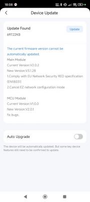
    also interesting that the BK7231N firmware now gets an update to v3.1.28 which uses the latest SDK version I've seen

    Code: Text
    Log in, to see the code


    Device software update screen indicating new versions for the main module and MCU module.

    Added after 2 [minutes]:

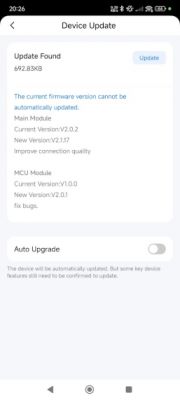
    only in November was it offering an update to v2.1.17


    Device update screen showing information about a new software version.
  • #19 21420879
    crg1darkspr1te
    Level 8  
    That's a neat collection you have there, I own an AT4P (dozen actually) and was wondering if you knew what the MCU instruction set was? Does not look like ARM so

    Having an update file to compare to the actual written bin is handy as it allows me to confirm the update mech in my own code.

    Keep up the good work, if I come across any more I shall share as it's a very handy resource for repair and learning.

    darkspr1te
  • #20 21420915
    divadiow
    Level 34  
    crg1darkspr1te wrote:
    was wondering if you knew what the MCU instruction set was? Does not look like ARM so

    hmm, unsure, but isn't the GD32E23x Series:

    Quote:
    Based on the Arm® Cortex® -M23 core with main frequency of up to 72MHz.


    so must be ARM?

    Added after 1 [minutes]:

    crg1darkspr1te wrote:
    if I come across any more I shall share as it's a very handy resource for repair and learning.

    yes, please do. I do like collecting things :D
  • #21 21420917
    crg1darkspr1te
    Level 8  
    Never mind, I noticed it used the same code style as the atorch gr2p and after checking photos I see it's a ch573 on riscv core, more specifically RV32IMAC which is supported in ghidra
    so if you see a lot of 0x6f and 3 bytes after that seems to be risc-V
    after dragging the AT4P file into ghidra and setting the right cpu it is decompiling nicely.


    darkspr1te
  • #22 21529481
    pheyi36hayo
    Level 1  
    I have one of this gadget. Recently, the device is not powering on completely.

    The green or blue light isn't coming on at all. And, when I press down the reset button, the red light just blinks 3 times.

    I have traced the fault to some capacitor and diode.
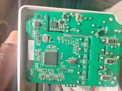
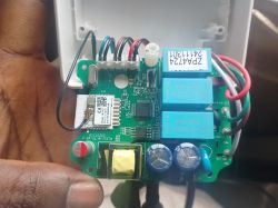
    CD3, C1, C4 and Diode (D3). They are all short. (Although, I still don't understand what could I have caused the issue. The problem probably started from CD3.

    What I need now is, can anyone help identify the rating of this component so I can replace with the appropriate parts.
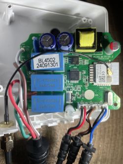
    Printed circuit board (PCB) with electronic components inside a casing.
    Close-up view of a circuit board inside an electronic device with visible relays, components, and wires.
  • #23 21530121
    crg1darkspr1te
    Level 8  
    The marking on that component CD3 are F45Z 680 10,
    I am guessing that's 680uF at 10V and it's a polymer type capacitor, as those parts are on the SMPS side I would say a surge may have caused it or a failed cap from heat could have also taken out D1 but that's just a guess.
    The fine folks on EEVBLOG would know,

    darkspr1te

Topic summary

The discussion revolves around the compatibility of the PC321-W-TY 3-phase energy meter, which utilizes the BK7231N MCU and ATT7022EU energy monitoring chip, with the OpenBeken firmware. Users confirm that the device is likely a TuyaMCU device, which is generally compatible with OpenBeken once the dpIDs are understood. Several users share their experiences with backing up the device's firmware and configuring it for power measurement, including mapping voltage and current channels. Issues such as device reboots and totalKWh resets are also addressed, with suggestions pointing to watchdog resets as a potential cause. Additionally, users discuss the flashing process and provide insights into the firmware structure and updates for the BK7231N and GD32E230 chips.
Summary generated by the language model.
ADVERTISEMENT