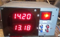
Test of eurorack power supplies (and not only, because plug-in ones too!) .
 .
.
Need, as they say, is the mother of invention.
As I am working with a modular eurorack system, and wanted to build myself an efficient power supply for the modular system in the box of a broken ATX power supply, and due to the problems arising during the construction of this power supply, about which there will probably be a separate article, the need arose to develop something that will comprehensively show the parameters of the obtained voltages at the same time. A multimeter can only measure one voltage at a time, and besides, by fiddling with the multimeter terminals while the unit is running, one can inadvertently short-circuit oneself. Industrial eurorack modules can cost over thousands of zloty.
This is how a simple but useful power supply tester was developed.
Just to clarify: the eurorack system is one of the standardised systems for modular synthesiser components (modules). It is, as some say, a hardware DAW. That is, a device used to create music. It is characterised by a module height of 3U - with reference to the 19" rack system - and a defined symmetrical supply voltage of +/-12V. In addition, a +5V voltage is provided for the digital modules, but this is not mandatory. The power supply is connected via an IDC10 connector for +-12V according to the standard imposed by Doepfer, and IDC16 for +-12V, 5V and two more control signals (CV and Gate). Most strictly analogue modules use the former, with most Eurorack enclosures providing the +5V extended power standard.
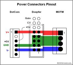
This is nicely shown in the illustration taken from the fonitronik website:
 .
.
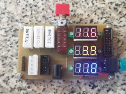
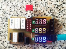
The tester was developed to be able to monitor all supply voltages on the power rail simultaneously, both at idle and under some load on the power supply. Three standard digital voltmeter modules were used, which provide sufficient measurement accuracy for the issue at hand. With the exception that the voltmeter for 5V is three-wire, where the power was routed from the +12V rail, due to the brightness of the displays being too low at the 5V supply voltage.
An Isostat-type bistable switch (I once salvaged a whole box of such switches from a telecoms lab dump) switches the load on all three lines of the power supply, in the form of 5W ceramic resistors. Their values have been chosen so as to achieve a current of about 250mA and not exceed the nominal power of the resistors. In addition, each voltage has one 1W resistor permanently switched on, which forces a current flow of about 20mA (which can be important for switching power supplies that sometimes don't like no-load operation). The panel voltmeter draws a maximum of 18mA with all segments lit, which may not have been enough, hence the added resistor. As you can see, the power supply under test does not make it to 5V when loaded.
 .
.
To increase the versatility of the tester, in addition to the two Eurorack sockets, I added other sockets I use in my designs, namely PWL5, a single row goldpin 6 socket with a key in position 2 (the standard marked DotCom in the illustration above), and a mini-DIN 6 socket which, because of the The mass availability of PS2 mouse and keyboard cables and KVM cables is sufficient to carry the three power supply voltages and ground. A typical 5.5/2.1 power supply socket is also available for the +12V voltage.
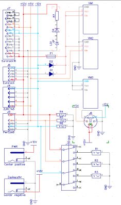
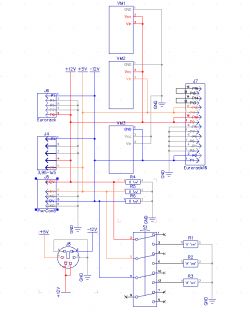
The schematic is simple and I only include it for the sake of completeness of the article.
 .
.
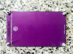
I sized the board to match the back panels I once ordered for the mini mixer and effects.
 .
.
To be completed is smoked plexiglass over the displays to improve the legibility of the displayed digits.
 .
.
Need, as they say, is the mother of invention.
As I am working with a modular eurorack system, and wanted to build myself an efficient power supply for the modular system in the box of a broken ATX power supply, and due to the problems arising during the construction of this power supply, about which there will probably be a separate article, the need arose to develop something that will comprehensively show the parameters of the obtained voltages at the same time. A multimeter can only measure one voltage at a time, and besides, by fiddling with the multimeter terminals while the unit is running, one can inadvertently short-circuit oneself. Industrial eurorack modules can cost over thousands of zloty.
This is how a simple but useful power supply tester was developed.
Just to clarify: the eurorack system is one of the standardised systems for modular synthesiser components (modules). It is, as some say, a hardware DAW. That is, a device used to create music. It is characterised by a module height of 3U - with reference to the 19" rack system - and a defined symmetrical supply voltage of +/-12V. In addition, a +5V voltage is provided for the digital modules, but this is not mandatory. The power supply is connected via an IDC10 connector for +-12V according to the standard imposed by Doepfer, and IDC16 for +-12V, 5V and two more control signals (CV and Gate). Most strictly analogue modules use the former, with most Eurorack enclosures providing the +5V extended power standard.
This is nicely shown in the illustration taken from the fonitronik website:
 .
.
The tester was developed to be able to monitor all supply voltages on the power rail simultaneously, both at idle and under some load on the power supply. Three standard digital voltmeter modules were used, which provide sufficient measurement accuracy for the issue at hand. With the exception that the voltmeter for 5V is three-wire, where the power was routed from the +12V rail, due to the brightness of the displays being too low at the 5V supply voltage.
An Isostat-type bistable switch (I once salvaged a whole box of such switches from a telecoms lab dump) switches the load on all three lines of the power supply, in the form of 5W ceramic resistors. Their values have been chosen so as to achieve a current of about 250mA and not exceed the nominal power of the resistors. In addition, each voltage has one 1W resistor permanently switched on, which forces a current flow of about 20mA (which can be important for switching power supplies that sometimes don't like no-load operation). The panel voltmeter draws a maximum of 18mA with all segments lit, which may not have been enough, hence the added resistor. As you can see, the power supply under test does not make it to 5V when loaded.

 .
.
To increase the versatility of the tester, in addition to the two Eurorack sockets, I added other sockets I use in my designs, namely PWL5, a single row goldpin 6 socket with a key in position 2 (the standard marked DotCom in the illustration above), and a mini-DIN 6 socket which, because of the The mass availability of PS2 mouse and keyboard cables and KVM cables is sufficient to carry the three power supply voltages and ground. A typical 5.5/2.1 power supply socket is also available for the +12V voltage.
The schematic is simple and I only include it for the sake of completeness of the article.
 .
.
I sized the board to match the back panels I once ordered for the mini mixer and effects.
 .
.
To be completed is smoked plexiglass over the displays to improve the legibility of the displayed digits.
Cool? Ranking DIY


