logo elektroda
logo elektroda
X
logo elektroda

OpenBeken Compatibility with CKW04 Chip in Woolley Smart Touch Switch?

ferbulous 1161 24
ADVERTISEMENT
  • #1 21300912
    ferbulous
    Level 18  
    Openbeken for CKW04 chip?

    I’ve recently replaced the pcb with esp for this switch

    https://www.reddit.com/r/esp8266/comments/gzh...ying_light_switches_from_aliexpress_ckw04_to/

    But I was wondering if there was any work done to add openbeken support if possible?

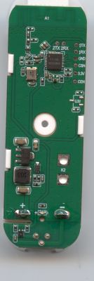
    Woolley Smart Touch Switch WiFi Push Button Light Switch No Neutral Wire Required RF Remote Control Smart Home Automation Module
    https://a.aliexpress.com/_mOjBhGi

    https://github.com/CoolKit-Technologies/DevDo...%BA%94%E7%94%A8%E6%8C%87%E5%AF%BC%E4%B9%A6.md

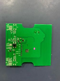
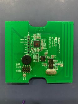
    PCB with ESP chipset and pin labels. CKW04 circuit board with electronic components.
  • ADVERTISEMENT
  • #2 21300967
    divadiow
    Level 34  
    I see a few mentions of this around the web, but at initial glance I don't see much mention of a full datasheet or SDK. Did you ever capture the UART boot log?
  • #3 21301167
    ferbulous
    Level 18  
    I tried getting the logs from rx/tx/uart0_tx/uart0_rx pins but nothing with 115200 baudrate.
    Maybe different baudrate?
    There's a LOG pad there but I'm not sure how to connect it to the uart
  • #4 21301206
    divadiow
    Level 34  
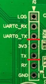
    I think I'd start by trying both of these to see which gives any output then try different bauds depending on how legible any of it is.

    Close-up of a circuit board with labeled UART pins and connectors.

    Added after 5 [minutes]:

    unless of course it's like some other devices where the RXs are to where they're to go TO not where they're FROM, in which case I'd try all 4 UARTs
  • #5 21301606
    ferbulous
    Level 18  
    >>21301206

    What are the usual baudrates that i could try?
  • #6 21301615
    divadiow
    Level 34  
    115200 feels the most common. 921600 perhaps. 74880 on some ESPs. I had 120000 on the ELM327 device the other day.
  • ADVERTISEMENT
  • #7 21301860
    p.kaczmarek2
    Moderator Smart Home
    Try to get boot log, maybe it will have some mentions of used SDK/toolset.
    Helpful post? Buy me a coffee.
  • #8 21302089
    divadiow
    Level 34  
    ferbulous wrote:
    There's a LOG pad there but I'm not sure how to connect it to the uart

    I didn't clock this whole post, or you added more info. anyway, I don't bother connecting the RX for log capture, only TX, so it doesn't need to be in pairs. Treat LOG as a TX and connect only that, common ground and 3V3 power as normal. Before that though, worth seeing if there's continuity from LOG to GND? Could LOG be some acronym for another ground? dunno
  • ADVERTISEMENT
  • #10 21302831
    p.kaczmarek2
    Moderator Smart Home
    That's not good news, but still, a bootlog could give us some more basic information. Maybe this chip is like T34 and is compatible with some "other" platform?
    Helpful post? Buy me a coffee.
  • ADVERTISEMENT
  • #11 21303798
    ferbulous
    Level 18  
    Ok, i'm getting something from LOG pad (as TX) with 115200. No continuity with GND

    bootloader start
    
    can not find ota_info.bin
    can not find ota.bin, plz use xmodem
    press 'm' to enter boot menu , remain 1 second
    fs addr ='0xfe000'
    heap size 142096
    invalid psram heap base
    ===================
    RT Config:        5  5  5  5  5  5  5 130 130  7  9 10  7  7  7  7  7  1
    HT Config:        5  5  5  5  5  5  5 170 170  7  9 10  7  7  7  7  7  1
    LT Config:        5  5  5  5  5  5  5 125 125  7  9 10  7  7  7  7  7  1
    ===================
    RF Gain:         4
    B Rate Gain:      7
    G Rate Gain:     13, 11,  9,  7
    20N Rate Gain:   13, 11,  9,  7
    40N Rate Gain:   13, 11,  9,  7
    Temperature Boundary:    35, 80
    ===================
    5G RT Config:    13 13 10  8 0x9264924a 0x96dbb6cc
    5G HT Config:    13 13 10  8 0x9264924a 0x96dbb6cc
    5G LT Config:    13 13 10  8 0x9264924a 0x96dbb6cc
    5G Band Threshold:       5150 5500 5700
    ===================
    rf config ch = -1, current ch = 7
    rf config tempe state = -1, current tempe state = 2
    page index byte len:         256
    object lookup pages:         1
    page pages per block:        16
    page header length:          5
    object header index entries: 105
    object index entries:        124
    available file descriptors:  4
    free blocks:                 257
    remove ota.bin rlt = -10002
    remove ota_info.bin rlt = -10002
    task Radio_Receive_T created
    radio init s
    radio init e
    if0 44:5D:5E:42:9B:82
    if1  44:5D:5E:42:9B:83
    MAC[44:5d:5e:42:9b:82]
    MAC[44:5d:5e:42:9b:83]
    task tcpip_task created
    task mode_task created
    [BUILD TIME]: Sep  6 2019 17:22:21
    task IDLE created
    task Tmr Svc created
    [fileInit] <2.dat> open failed, fd: -10002
    [fileInit] file not found
    task event_handle_ta created
    task pair_task created
    sniffer_mac:6
    start_sniffer_mode
    reset key tbl
    tx flow: 735
    rx flow: 4
  • #13 21311332
    divadiow
    Level 34  
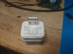
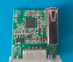
    I've found nothing else, but for the hell of it I ordered a Sonoff Micro-CFH and they do still come with a CKW04 chip

    Sonoff Micro-CFH USB adapter Close-up of a circuit board featuring a chip labeled CKW04.

    LOG:
    Code: Text
    Log in, to see the code


    Added after 16 [minutes]:

    quite a few of those "ffs..." strings get results in Github. eg:

    https://github.com/search?q=ffsInitializeConfigurationMapEntryStream&type=code
    https://github.com/search?q=ffsInitializeUserContext&type=code

    Maybe it's a MicrochipTech chip at heart.

    Added after 31 [minutes]:

    divadiow wrote:
    Icomm-Semi use start_sniffer_mode

    oh maybe it is Icomm Semi - https://www.cnx-software.com/2019/12/12/icomm...-andes-risc-soc-for-iot-and-embedded-systems/

    Added after 1 [hours] 45 [minutes]:

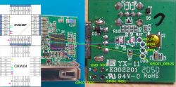
    Assuming it's an Icomm Semi SV6166F, here's where the pads on the Sonoff trace to. CKW04 and SV6166F and the function of pads appear to line up.

    Diagram of SV6166F chip and comparison with Sonoff board.

    and from the CKW info pages for those traced:
    Table showing GPIO pins and their functions.

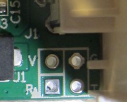
    These 4 test holes are clearly for programming

    Close-up of a circuit board with four test holes labeled as V, R, C, and T.

    The only thing I'm not sure about is why GPIOs 3 and 4 need test pads.
  • #14 21312063
    ferbulous
    Level 18  
    Thanks @divadiow for your extra work on this
    How were you able to get more log output? Mine just stops after tx/rx line and I’m not too sure about wiring to the main line with the uart tx/rx/gnd still connected to it
  • #15 21312117
    divadiow
    Level 34  
    ferbulous wrote:
    How were you able to get more log output?

    I assume it's because I have a different device and it was coded to output more.

    ferbulous wrote:
    I’m not too sure about wiring to the main line with the uart tx/rx/gnd

    definitely don't do this. I guess there's a possibility yours is dying from lack of power around the time wifi initialises, but I would think it would boot loop and you'd see the same output repeated. Does the log repeat over and over or does it show once and the device remains steady in pairing mode?
  • #16 21312199
    p.kaczmarek2
    Moderator Smart Home
    If GPIO roles match up with existing known chip, then it may be it.

    The UART log output can say more when it's being paired to the cloud or when you control it via Tuya app.
    Helpful post? Buy me a coffee.
  • #18 21478212
    insmod
    Level 22  
    >>21312234 A partial sdk can be found for ssv6006 target on hi-flying ftp you posted earlier.
    Download LPD100 and look inside, perhaps it contains something for 6166.
    target_def.mk mentions ANDES_N10 arch, same as in 6166.
  • #19 21478292
    divadiow
    Level 34  
    plenty of 6006, like you say
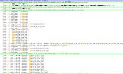
    Screenshot showing search results of text in files with highlighted found fragments.

    and actually some 6166 and ICOMM, presumably the ICOMM Semi mentioned months ago
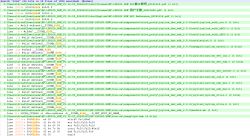
    Screenshot of code search results in SDK files.

    Added after 2 [minutes]:

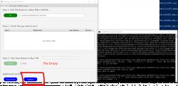
    interesting
    Screenshot showing the Flash Burn Tool with a BIN file open.

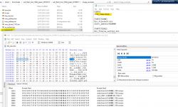
    Added after 21 [minutes]:

    Screenshot showing the contents of a hex editor and an open configuration file.

    Added after 24 [minutes]:

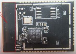
    HF-LPD100 = SV6266F
    Electronic module with visible SV6266F chip
  • #20 21478385
    insmod
    Level 22  
    >>21478292 From what i understood the only difference between them is that 6266 supports 5ghz wifi.
    Did you try to take a backup yet?
  • Helpful post
    #21 21478393
    divadiow
    Level 34  
    not yet. will try shortly.

    Added after 52 [minutes]:

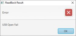
    hmm. I think this tool might be actual USB programming? there's no mention of UART and:
    Dialog window with error message USB Open Fail.

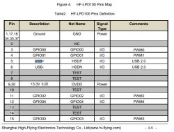
    and there is USB interface
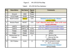
    Table showing HF-LPD100 pin definition with various signals and comments.

    Added after 5 [minutes]:

    relevant docs
  • Helpful post
    #22 21478503
    divadiow
    Level 34  
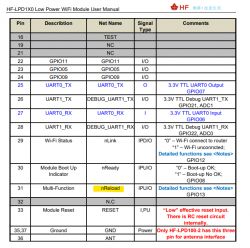
    seems GPIO13 - nReset - needs to be low on reset for download mode
    Pin table of HF-LPD1X0 WiFi module with signal descriptions.

    or maybe GPIO4?
    Table of HF-LPD130 pin definitions with descriptions and comments.

    3 and 4 seems exposed on Sonoff, not 13. pulling 3 and 4 low doesn't seem to do anything but boot device normally
  • #24 21479961
    divadiow
    Level 34  
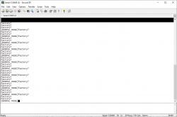
    Screenshot of SecureCRT program showing serial console output.

    Code: Text
    Log in, to see the code


    on every boot from TXD1/GPIO7 @9600 baud
  • #25 21520722
    p.kaczmarek2
    Moderator Smart Home
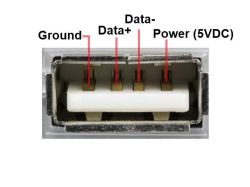
    I've actually seen HSDP and HSDM, which suggests D+ and D- in a related topic:
    https://www.elektroda.com/rtvforum/topic4117636.html#21520720
    So it's an USB, after all?
    divadiow wrote:

    hmm. I think this tool might be actual USB programming? there's no mention of UART and:
    Dialog window with error message USB Open Fail.

    and there is USB interface
    Table showing HF-LPD100 pin definition with various signals and comments.


    USB Type A connector with labeled pins: Ground, Data+, Data-, Power (5VDC).
    Helpful post? Buy me a coffee.

Topic summary

The discussion revolves around the compatibility of OpenBeken firmware with the CKW04 chip used in the Woolley Smart Touch Switch. The user has replaced the original PCB with an ESP module and is seeking information on OpenBeken support for the CKW04. Participants suggest capturing UART boot logs to gather more information about the chip's SDK and configuration. Various baud rates are discussed for UART communication, with 115200 being the most common. The user successfully retrieves boot logs indicating the chip's operational status, but continuity issues with the ground are noted. Further exploration of the chip's compatibility with existing platforms and potential connections to other devices is suggested.
Summary generated by the language model.
ADVERTISEMENT