logo elektroda
logo elektroda
X
logo elektroda

[RTL8710CF] How to Reflash Firmware on Kasa HS200 WiFi Smart Switch (US)

Jerther 1506 40
ADVERTISEMENT
  • Helpful post
    #1 21384347
    Jerther
    Level 4  
    Kasa Smart Single Pole Light Switch by TP-Link (HS200)

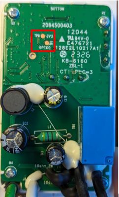
    The case is a bit difficult to crack open, but it's possible by using only a flat head screwdriver and by prying the sides. Here's the PCB on both sides:
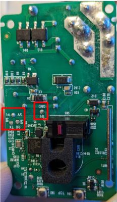
    PCB of TP-Link Kasa HS200 light switch with marked pads.

    View of the backside of the TP-Link Kasa HS200 smart light switch PCB with marked GPIO0 and 3V3 pads.

    I connected the 5V pad on the PCB to the 5V rail of the USB Serial Converter. The rest of the pads are clearly labeled in the pictures. It's like it was meant to be reflashed ;)

    Short the GPIO0 pad to the 3V3 pad next to it to enable bootloader mode. Use the "Restart" tact switch to restart the MCU. The "Reset" tact switch is just another input.

    The rest is easy! Follow this guide to flash the firmware: https://www.elektroda.com/rtvforum/topic4097185.html

    Here's a partial template I've come up with. It allows control of the relay and the main LED by the main switch. The "Reset" switch and the tri-color "wifi" LED are mapped but I'm not sure what to do with them. I'd like to use them for their original intended purpose but I don't know how. I hope that helps :)

    Code: JSON
    Log in, to see the code
  • ADVERTISEMENT
  • #2 21385105
    divadiow
    Level 35  
    thank you for the template and the firmware backup you sent. I've not been able to get it into a pairable state to determine much from it at this point.
  • #3 21385142
    max4elektroda
    Level 20  
    Jerther wrote:
    the tri-color "wifi" LED are mapped but I'm not sure what to do with them. I'd like to use them for their original intended purpose but I don't know how.

    There are "LED_WIFI" and "LED_WIFI_n" to use the WiFi LED. Will they do what you want?
  • #4 21385370
    Jerther
    Level 4  
    max4elektroda wrote:
    Jerther wrote:
    the tri-color "wifi" LED is mapped but I'm not sure what to do with them. I'd like to use them for their original intended purpose but I don't know how.

    There are "LED_WIFI" and "LED_WIFI_n" to use the WiFi LED. Will they do what you want?

    I just found the documentation for pin roles. I'll do some tests.

    https://github.com/openshwprojects/OpenBK7231T_App/blob/main/docs/ioRoles.md

    Added after 7 [hours] 1 [minutes]:

    I have fiddled a bit with the LED_WIFI roles and the best I could come up with is to use the green led, and it follows the behavior described in the documentation but that's quite a bit far from the original:

    Blinking Amber and Green: App-Config mode initiated.
    Green: Lit up for about 30 seconds when successfully connected to the Wi-Fi network, then turns off.
    Blinking Amber: Resetting.
    Red: No Wi-Fi connection.

    Now it's ok if the behaviors are different, but the led staying lit is a bit annoying, and I'd like to make use of the red and amber colors too if that's possible.

    The led works by combining P7 and P9:
    P7 only = green
    P9 only = red
    P7+P9 = amber

    Any ideas?
  • #5 21424140
    divadiow
    Level 35  
    did you get any further since you last posted? I forgot about this thread and have not yet posted added your template

    Added after 20 [minutes]:

    info from dump

    Code: Text
    Log in, to see the code
  • #6 21424326
    Jerther
    Level 4  
    I haven't. My last post is as far as I went.
  • ADVERTISEMENT
  • #7 21424343
    divadiow
    Level 35  
    how would you like the LEDs to behave?

    Flashing amber for wifi connecting? (not even sure you can assign two wifi_led roles and they function together without some autoexec script)
    then green for socket on and red for socket off?

    Added after 11 [minutes]:

    I've assigned a two-LED plug I have both WifiLed and they behave as one - purple wifi connecting indicator in my case - red/blue
  • #8 21424498
    Jerther
    Level 4  
    It would be nice if the wifi LEDs behaved like the original and used the full three colors. If it is not possible, then at least have the green led turn off after some time when wifi is connected. Right now it is always lit and it's a bit annoying because of the way the switch was designed.
  • #9 21425991
    Jerther
    Level 4  
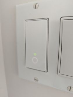
    Here's what the switch looks like when it's on with my current template. The white circle is on when the switch is on, and it is off when the switch is off. The green wifi LED is always lit.

    Wall switch turned on with green wifi LED and glowing white circle.
  • #10 21426900
    divadiow
    Level 35  
    I guess it'd be something to script, change the role of each pin depending on the state of the wifi (or other state/trigger). Here's a basic example that could be built upon

    https://www.elektroda.com/rtvforum/topic4012418.html#20804036

    Added after 18 [minutes]:

    https://github.com/openshwprojects/OpenBK7231T_App/blob/main/docs/autoexecExamples.md

    https://github.com/openshwprojects/OpenBK7231T_App/blob/main/docs/commands-extended.md

    Added after 1 [minutes]:

    https://youtu.be/kXi8S12tmC8?si=0ni9o9E2WePYspU_
  • #11 21490774
    Jerther
    Level 4  
    I haven't had time to play with scripts yet, but I've had a wifi outage yesterday. Of course the wifi led on the switch started to blink red-green in alternance, which is expected. But once the wifi came back up, the switch did not reconnect automatically. The wifi led kept on blinking for hours, until I hit the small "restart" button on the switch. Then it reconnected fine.

    It's like the microcontroller gives up reconnecting at some point, and I believe it's not intended, because other IoT devices I've reflashed with openbk reconnected without my intervention.
  • #12 21528518
    divadiow
    Level 35  
    ah interesting. That's a bit of a show-stopper for RTL87X0C devices running OpenRTL.

    I think @max4elektroda did some stuff on several platforms regarding wifi reconnection behaviour, but maybe that was (just?) SSID2 support.

    Added after 3 [minutes]:

    and maybe @insmod who ported RTL
  • #13 21528550
    insmod
    Level 25  
    I don't have a RTL87X0C device, but i have RTL8710B and RTL8720D devices running, and they all share wifi code.
    What version are you using? I improved wifi code some, previously it could've crashed the device. Also, in recent update i turned on realtek own auto reconnect feature, in addition to openbeken one.
    I don't have problems with wifi anymore, and my RTL8710B plug uptime is at about a month, with wifi outages.
    This particular plug is pretty unstable with wifi when there's any load. I've had 1.5 hours today of when the plug disconnected and didn't reconnect, but it eventually did.
    You could also try to enable flag 51, but i doubt that it would change anything.
  • #14 21528562
    max4elektroda
    Level 20  
    divadiow wrote:
    I think @max4elektroda did some stuff on several platforms regarding wifi reconnection behaviour, but maybe that was (just?) SSID2 support.

    Yes, some SSID2 stuff and a faster try for reconnect during the first seconds after startup.
    All the WiFi code is usually in a library blob from the manufacturer, I expect the same here.
    If you don't have a serial connection to see logs during this time it will be hard to figure out. Maybe SSID is not found, authentication failed...
  • #15 21528635
    Jerther
    Level 4  
    The version I'm using is the one introducing support for RTL8710C. I understand there's been multiple improvements since, so I'll update the firmware and check if I can make the switch fail to reconnect again.

    Meanwhile, what needs to be done about the template so it makes the official list?
  • #17 21528672
    Jerther
    Level 4  
    No way! :D

    So it looks like I'm golden then! Nice! I will report back if I find anything about the WiFi.
  • ADVERTISEMENT
  • #18 21528674
    divadiow
    Level 35  
    well, that PR's been open a month, I think @p.kaczmarek2 has been busy
  • #19 21528696
    p.kaczmarek2
    Moderator Smart Home
    There are no pending Web App pull requests?
    Helpful post? Buy me a coffee.
  • #20 21528701
    divadiow
    Level 35  
    oh dear. my bad 😳

    would help if I had opened one
  • #21 21528804
    Jerther
    Level 4  
    1.18.12

    "Sorry, OTA update not implemented for OpenRTL87X0C"

    Oh no :( so I have to remove the switch from the wall and reflash the firmware the hard way...

    Is OTA implemented in later versions, so I don't have to do that again?
  • #22 21528805
    insmod
    Level 25  
    >>21528804
    OTA was implemented even before the release, so don't worry.
  • Helpful post
    #23 21528852
    max4elektroda
    Level 20  
    Jerther wrote:
    Sorry, OTA update not implemented for OpenRTL87X0C

    I don't recall if the "new" OTA on the Configure menu was present in that version, maybe it wasn't. If that's the problem you should be able to do OTA from the Web App.

    Added after 20 [minutes]:

    Just checked the code, that should be the case, this new approach for OTA was implemented while @insmod was doing the heavy lifting with OpenRTL so it's not present in 1.18.12 yet.
    But Web Application OTA should work
  • #24 21529248
    Jerther
    Level 4  
    Ok there's an OTA menu in the web app. Phew! šŸ˜…
  • #25 21535393
    Jerther
    Level 4  
    I went ahead and ordered about a dozen of these switches and while the MCU is the same, the board layout is different. Shouldn't be a problem since all test points are still accessible. I'll post pictures and more details when I can.
  • ADVERTISEMENT
  • #27 21550066
    p.kaczmarek2
    Moderator Smart Home
    Thank you, merged. Let me know if you have any futher ideas for improvements.
    Helpful post? Buy me a coffee.
  • #28 21598616
    Jerther
    Level 4  
    Ok so four updates:

    1) I've made a new PR to set the wifi led to actual wifi led in the configuration: https://github.com/OpenBekenIOT/webapp/pull/207

    2) I have no picture of the new PCB revision, but all the test pads are still present, and on the same side of the PCB. You need to remove the little foam pad to access one of them.

    3) We've stopped using devices from Kasa at work after one had a capacitor blow up. A quick search on google revealed that many MANY of these devices suffer the same fate, so we've stopped using them. BUT at home I still use them and I've preventively replaced the suspicious cap (the only 470µF 10V) by a Rubicon 470µF 16V 8000h@105C. Should last a while ;)

    4) I've started using the MQTT feature with home assistant. The switch works fine, but the extra info (build, IP, rssi, ssid, uptime) all become "unknown" after a while. Any clue why this happens?
  • #29 21605761
    Jerther
    Level 4  
    @p.kaczmarek2 can you take a look at the PR I mentioned in my previous comment?
  • #30 21605763
    p.kaczmarek2
    Moderator Smart Home
    Sure, I merged it, however it looks like just a LED role swap, so probably there are two LEDs with different colors?
    Helpful post? Buy me a coffee.

Topic summary

The discussion focuses on reflashing the firmware of the TP-Link Kasa HS200 WiFi Smart Single Pole Light Switch using the RTL8710CF microcontroller. The device's PCB is accessible by prying open the case, revealing clearly labeled pads for serial connection. Bootloader mode is enabled by shorting GPIO0 to 3.3V and restarting the MCU. A partial firmware template was shared, enabling relay and main LED control, with mapping for the reset switch and tri-color WiFi LED. Users explored LED behavior customization, noting the WiFi LED uses pins P7 and P9 to produce green, red, and amber colors, but replicating the original LED patterns proved challenging. Suggestions included scripting pin roles dynamically based on WiFi state. Firmware versions supporting RTL8710C were discussed, highlighting improvements in WiFi reconnection and OTA update capabilities. OTA updates are not implemented in early versions (e.g., 1.18.12) but are available via the Web App in later releases. Issues with WiFi reconnection after outages were reported, with some devices requiring manual restart. Contributions included a pull request to enable the reset button to trigger safe mode. Newer switch batches with different board layouts but the same MCU were mentioned, with test points remaining accessible for reflashing.
Summary generated by the language model.
ADVERTISEMENT