 .
.
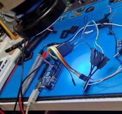
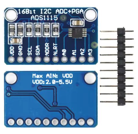
Here I will introduce the ADS1115, which is a 4-channel, 16-bit ADC. The ADS1115 is available to buy in our country for a dozen or so zlotys, and can be imported from abroad for up to half the price. The ADS1115 uses the I2C protocol, so it is possible to connect as many as four separate such modules on a single bus, thus obtaining 16 ADC channels. The ADS1115 also offers differential operation and a programmable gain value, allowing small voltage variations to be measured.
 .
.
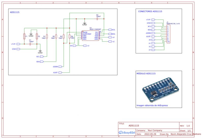
I have included a diagram of the popular commercially available ADS1115 module below:
 .
.
How to connect the ADS1115? .
Connecting the finished module is really very simple, as everything needed is already present on the board. The I2C bus requires resistors pulling up the SDA and SCL lines to supply power, but the finished module has these resistors already present on board. For this reason, connecting the whole thing comes down to using four wires, power (2.0V to 5.5V), ground, SDA and SCL.
If using hardware I2C, check which pins on our MCU board have this role. The Arduino UNO SDA is at A4 and SCL is A5.
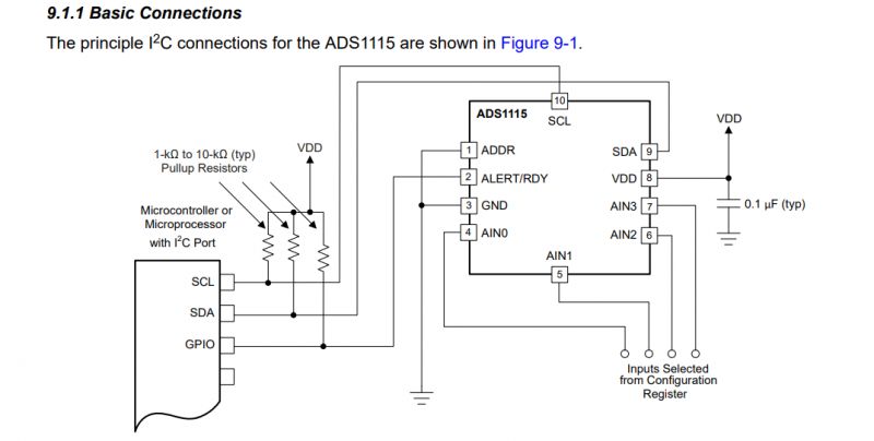
If you are planning to make your own board, then you can base it on the schematic from the datasheet note:
 .
.
This is how several ADS1115s are connected on one bus:
 .
.
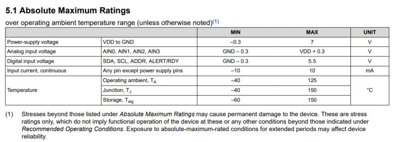
When connecting the inputs, care must also be taken to ensure that the voltage on them does not exceed the supply voltage of the entire module. This is specified in the catalogue note, section "Absolute Maximum Ratings":
 .
.
The commercially available ADS1115 module has no additional protection on the board.
How to test the ADS1115? .
The ADS1115 is an ADC, which means it converts an analogue signal into a digital signal. In simple terms, it performs a voltage measurement. In this case, we only need one potentiometer. Its outermost legs are connected to the power supply (5V or 3.3V), and to GND, while the middle leg is connected to one of the ADS1115 inputs. The potentiometer connected in this way is a voltage divider, and this voltage can be read from the ADS.
How to select the address of the ADS1115? .
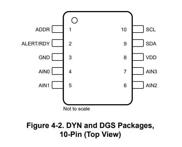
It would seem that one ADR pin would be two address options - because it can be connected to either the high or low state - but no:
 .
.
Here we have 4 options - because you can still connect the ADR to SCL or SDA:
 .
.
The ADS1115 communication protocol .
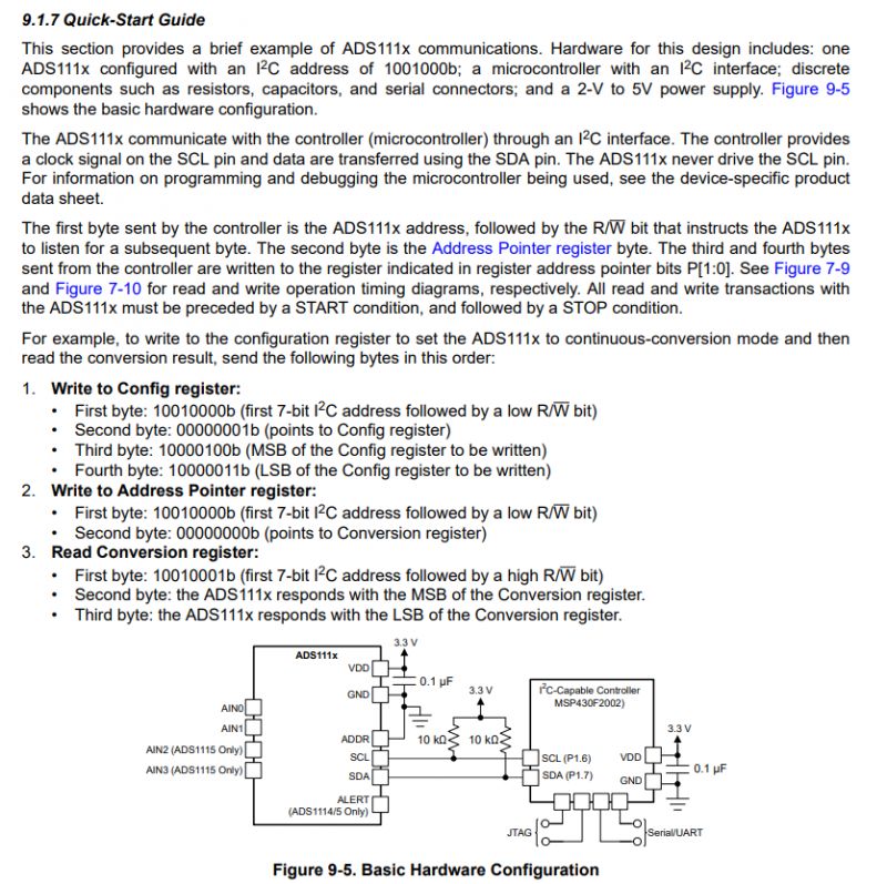
Getting the ADS1115 up and running in terms of communication protocol is best described in the 'Quick-Start Guide' section of the catalogue note:
 .
.
Personally, I would add here that it's a good idea to run some sort of I2C scan first, if only based on the example code from the Arduino, so that you can make sure you've connected everything correctly.
Reading from the ADS1115 is done in two stages:
- we send bytes to the Config register, these define the operating mode and the channel we are reading from (point 1 in the screenshot)
- after now start reading the result from the Conversion register (points 2 and 3)
Config Register
For a detailed description of the bits of the Config Register, I refer you to the data sheet.
How to run ADS1115 with Arduino? .
You can use a ready-made library (to be added via Libraries):
https://docs.arduino.cc/libraries/ads1115_we/
Code: C / C++
You can also do a simple readout yourself. All you need is the Wire library:
Code: C / C++
First step 1 from the documentation is executed, i.e. the writeConfig function. It defines the operating mode and the channel to be read. Then steps 2 and 3 are performed, i.e. reading two bytes from CONVERSION_REGISTER.
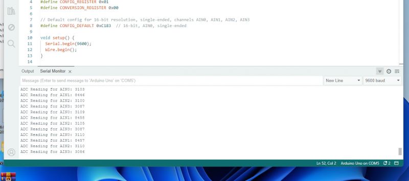
The result:
 .
.
Visualisation of communication with ADS1115 .
The communication can be viewed with the Sigrok analyser:
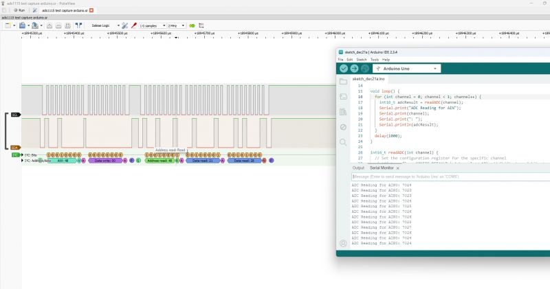 .
.
I presented it in the topic:
Salae 24MHz logic state analyzer for £40 - analysis of unknown LED display protocol .
There is an 8ms interval between stages to allow the module to convert:
 .
.
The first stage is to send data to the configuration register at address 0x01, in this case 0xC183 is sent to it. All contained in a single transaction, preceded by an I2C start condition and ended by a stop:
 .
.
The second stage is the readout. Here, separately after the start we send the register address to be read (this is a write, so the 0x48 device address is with Write - 0 bit), and then separately (after the stop and start) we send the 0x48 device address with Read - 1 bit and read two bytes. After the first byte read there is an ACK, because we want to read further, after the second one there is already a NACK:
 .
.
Running with BK7231 .
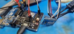
We've also run the ADS1115 with the BK7231, so you can also easily report its measurements to Home Assistant, but I'll put the details in a separate topic.
 .
.
Summary .
This was a brief demonstration of the ADS1115 module. Getting this module up and running is hassle-free, we have ready-made libraries for the Arduino, and if you want to implement its communication yourself there's not much work anyway - basically one "write" and one "read" from a given address. This isn't the BME280 or there BMP280, where I wouldn't be too keen on creating a controller myself.
The ADS1115 is capable of a bit more than I've shown, so it's possible I'll try a separate project on it, maybe some voltage or current measurement there (on a shunt), maybe I'll also separately run that ALERT pin and do a read that isn't blocking (without that delay in my example code). This will all be in the next topic already.
I'm attaching related material, the datasheet note I relied on, there are details of the PGA configuration etc (if you want to implement this yourself), and the captured communication from the ADS1115 in the format for PulseView:
.
.
Have you already used ADS1115 in your projects, and if so, for what? .
Cool? Ranking DIY Helpful post? Buy me a coffee.


