Hello
A short report on the disassembly of the EARU EAEMP3C-100-TY-W.
 .
.
Fig. 1. Device without front casing commissioned without CB3S module
The individual modules of the device can be separated without the use of a soldering iron, they are seated on golpins.
The measuring system of the device is the RENERGY RN8302B, to which the measuring coils are connected, the whole is managed by the CMS32L051 chip, which contains an ARM® Cortex®-M0+ 32bit core, and for the display of the parameters there is an LCD display with colour backlighting/film under part of the screen - it looks quite nice.
There are 2 measurement screens to choose from in the device settings. The nominal unit works with TUYA and you configure it through their app. The whole thing is quite easy to configure and works 'out of the box', BUT A LOT OF SETTINGS ARE ONLY AVAILABLE FROM THE APP.
A measuring coil can be connected to the device to measure leakage. The dimensions of the coil are quite large about 76mm outer diameter, resistance about 90 Ohm, inductance about 76H (measurement of inductance uncertain because with some old meter with a weak battery), described as AC2000:1 on aliex.... .
The unit, when powered (it is powered ONLY from phase L1 and N), draws 1W, when WiFi is configured approx 1.3-1.5W with relays on.
The CB3S WiFi module is easily removable, the photo shows the pinout, except that if you want to flash the device you need to connect directly to the module with 3.3V power supply - the power supply from the goldpin is controlled by a transistor.
The device is quite interesting due to the possibility of protection against too high, too low voltage, lack of one of the phases, it also has the possibility of setting the minimum and maximum current and time operation, the time of triggering the protection can be set, also the time of return to work is configurable. The device is described as 3P+N 1-100A - which is probably correct 100/4=25A or 100/3=33A is rather the max what the relays can withstand;) . The unit is capable of bi-directional energy counting, basically it displays the sum of energy consumed and produced, by clicking the arrow buttons we can see the individual components of the sum.
This much could be ascertained before the device was 'broken', when using the BK7231GUIFlashTool-v5 software there was a problem connecting to rip the software, and during one attempt before the soft landed on the disk I managed to press the Write key instead of Read, and this of course went like this the first time. A strange program by the way, when trying to read it pops up several windows making a simple read difficult. It is not possible to read the memory into the buffer first and then write the file, while write simply fires without any question.
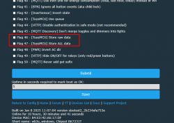
As the OpenBK7231N_QIO_1.18.23 software has been installed I don't have much left.... By trial and error I managed to find a few dpid, unfortunately only a part. Currently most of the dpID is captured and described. the recommended firmware is at least OpenBK723131N_1.18.30.
Below is the autoexec that I managed to put together, however it is definitely up for improvement (it would be nice if someone corrected it), the readout of phase parameters measuring power consumption, power factor, and leakage current, temperatures and a few configuration parameters works.
The code provided, however, manages to crash and not give any other measurement except the last/start measurement. The dpid capture with the "tuyaMcu_sendQueryState" command does not work, at least on this version of OpenBK (or I don't know how to handle it).
The wifi settings reset key does not work properly - although the logs show it is supported - the WiFi reset command appears, it would be nice if it reset the wifi to factory settings as it did in the original softy.
After selecting more than 32 dpid the next one can be saved, but to delete it you have to format the whole device. Currently thanks to the invaluable help of p.kaczmarek2 autoexec is practically finished.
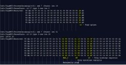
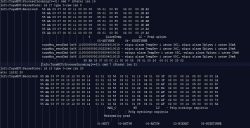
Some of the settings appear in the debug log only after saving the settings on the meter - I wonder if any command can trigger such a report - TAK write dpID18 ? Below is such a message:
.
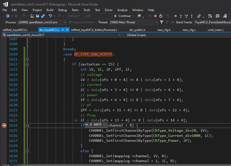
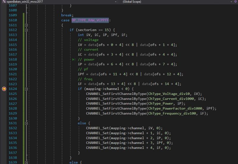
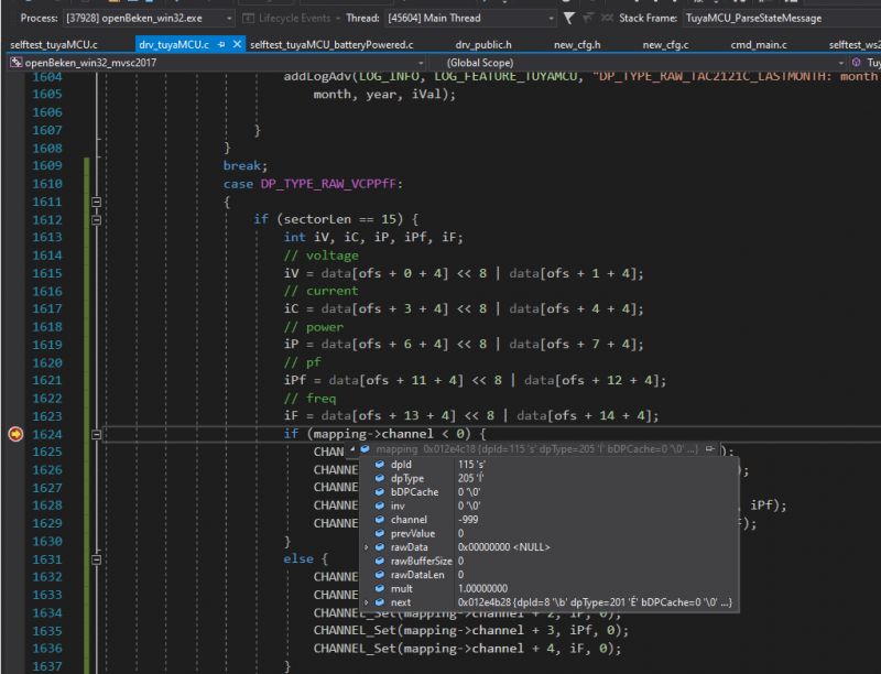
I can't see the grid frequency anywhere - the meter gives it after the decimal point, e.g. 49.9Hz... dpID113-115 contained this information.
Dump of the software will not be done for now, there was an attempt to do a Frankenstein with the soft from EAEMP3-100-TY-W (transferred settings and rf region), but the CB3S module did not start then. If anyone has such a meter let's drop a dump please - it will be easier to refine the boot script.
Greetings!
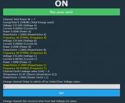
This works: reading voltage,current,power,powerfactor and frequency for all 3 phases. Here note - the frequency measurement is cheated the frequency of the power phase is copied in the MCU to the other phases.
Leakage current reading, energy produced and consumed, device temperature reading, WiFi reset are all operational. The dpID of the alarm settings are known, but they are complex and can only be configured on the command line for now - there are examples in autoexec, error codes are known - they are listed in this topic.
Only the operating schedule is missing - dpID117 is 90% responsible for it.
Below is the view from the interface.
 .
.
.
 .
.
Fig. 2. Relay board, with measurement circuitry visible ReEnergy RN8302B .
 .
.
Fig. 3. Top view of the relays themselves, measuring coils on individual phases visible, neutral track not interrupted.
 .
.
Fig. 4. The other side of the relay board showing the power supply based on the circuit with the description "8231H Q24A1006"
 .
.
Fig. 5. Board with MCU CMS32L051 , display controller TM1622B , and 24C64 eeprom.
 .
.
Fig 6. The same board from a different angle visible circuit markings.
 .
.
Fig 7. The board with the display also visible buttons for operation.
 .
.
Fig. 8. CB3S WiFi communication module based on BK7231N chip (screen not removed).
 .
.
Figure 9: Relay including current leakage measurement coil.
 .
.
 .
.
Figure 10-11: Scan of instructions
 .
.
Fig 12. A snapshot of the auction view.
The goodies have arrived thanks!
 .
.
A short report on the disassembly of the EARU EAEMP3C-100-TY-W.
 .
.
Fig. 1. Device without front casing commissioned without CB3S module
The individual modules of the device can be separated without the use of a soldering iron, they are seated on golpins.
The measuring system of the device is the RENERGY RN8302B, to which the measuring coils are connected, the whole is managed by the CMS32L051 chip, which contains an ARM® Cortex®-M0+ 32bit core, and for the display of the parameters there is an LCD display with colour backlighting/film under part of the screen - it looks quite nice.
There are 2 measurement screens to choose from in the device settings. The nominal unit works with TUYA and you configure it through their app. The whole thing is quite easy to configure and works 'out of the box', BUT A LOT OF SETTINGS ARE ONLY AVAILABLE FROM THE APP.
A measuring coil can be connected to the device to measure leakage. The dimensions of the coil are quite large about 76mm outer diameter, resistance about 90 Ohm, inductance about 76H (measurement of inductance uncertain because with some old meter with a weak battery), described as AC2000:1 on aliex.... .
The unit, when powered (it is powered ONLY from phase L1 and N), draws 1W, when WiFi is configured approx 1.3-1.5W with relays on.
The CB3S WiFi module is easily removable, the photo shows the pinout, except that if you want to flash the device you need to connect directly to the module with 3.3V power supply - the power supply from the goldpin is controlled by a transistor.
The device is quite interesting due to the possibility of protection against too high, too low voltage, lack of one of the phases, it also has the possibility of setting the minimum and maximum current and time operation, the time of triggering the protection can be set, also the time of return to work is configurable. The device is described as 3P+N 1-100A - which is probably correct 100/4=25A or 100/3=33A is rather the max what the relays can withstand;) . The unit is capable of bi-directional energy counting, basically it displays the sum of energy consumed and produced, by clicking the arrow buttons we can see the individual components of the sum.
This much could be ascertained before the device was 'broken', when using the BK7231GUIFlashTool-v5 software there was a problem connecting to rip the software, and during one attempt before the soft landed on the disk I managed to press the Write key instead of Read, and this of course went like this the first time. A strange program by the way, when trying to read it pops up several windows making a simple read difficult. It is not possible to read the memory into the buffer first and then write the file, while write simply fires without any question.
As the OpenBK7231N_QIO_1.18.23 software has been installed I don't have much left....
Below is the autoexec that I managed to put together,
The code provided, however, manages to crash and not give any other measurement except the last/start measurement. The dpid capture with the "tuyaMcu_sendQueryState" command does not work, at least on this version of OpenBK (or I don't know how to handle it).
The wifi settings reset key does not work properly - although the logs show it is supported - the WiFi reset command appears, it would be nice if it reset the wifi to factory settings as it did in the original softy.
After selecting more than 32 dpid the next one can be saved, but to delete it you have to format the whole device.
Some of the settings appear in the debug log only after saving the settings on the meter - I wonder if any command can trigger such a report - TAK write dpID18 ? Below is such a message:
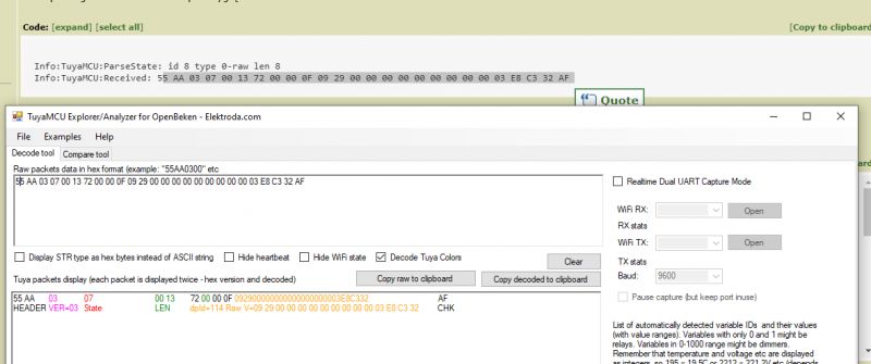
00 18 12 00 00 14  01 01  *03 2A*  03 01 *01 04*  04 01 *00 B2*  0200 00 14 05 00 00 00 51
00 18 12 00 00 14  01 01  *03 2A*  03 01 *01 06*  04 01 *00 B3*  0200 00 14 05 00 00 00 54
			01=ON*MAX_C*	 03=ON*VH VH*	04=ON*VL VL*	02=OFF-3PhaseCurrent inbalance 05=OFF- Lack of 1 Phase disabled
Dump of the software will not be done for now, there was an attempt to do a Frankenstein with the soft from EAEMP3-100-TY-W (transferred settings and rf region), but the CB3S module did not start then. If anyone has such a meter let's drop a dump please - it will be easier to refine the boot script.
Greetings!
This works: reading voltage,current,power,powerfactor and frequency for all 3 phases. Here note - the frequency measurement is cheated the frequency of the power phase is copied in the MCU to the other phases.
Leakage current reading, energy produced and consumed, device temperature reading, WiFi reset are all operational. The dpID of the alarm settings are known, but they are complex and can only be configured on the command line for now - there are examples in autoexec, error codes are known - they are listed in this topic.
Only the operating schedule is missing - dpID117 is 90% responsible for it.
Below is the view from the interface.
 .
.
// EAMP3C-100-TY-W ver.109 autoexec, min.ver. OpenBK7231N_1.18.30 needed!
startDriver TuyaMCU
tuyaMcu_setBaudRate 9600
startDriver NTP
ntp_timeZoneOfs 1 //optional

// This one is better than tuyaMcu_defWiFiState 4;  MQTTState 1 = WiFiState 4
// issuing of tuyaMcu_defWiFiState 4 continues the script,
// but doesnt report to MQTT since there is still no connection.
// if you didn't setup MQTT connection then issue tuyaMcu_defWiFiState 4
// and comment waitFor MQTTState 1

// waitFor MQTTState 1
tuyaMcu_defWiFiState 4

// Main Relay - Dpid 16 "switch" -> Channel 1
linkTuyaMCUOutputToChannel 16 bool 1
setChannelType 1 toggle
setChannelLabel 1 "Main power switch"

// Total energy Used - Dpid 1 "Energy Used" -> channel 2
linkTuyaMCUOutputToChannel 1 val 2
setChannelType 2 EnergyTotal_kWh_div100
setChannelLabel 2 "Total Energy used"

// Dpid 110 "Dpid 110" Energy Produced-> channel 3
linkTuyaMCUOutputToChannel 110 val 3
setChannelType 3 EnergyTotal_kWh_div100
setChannelLabel 3 "Produced Energy kWh"

// Total Power Dpid 111 -> channel 4
linkTuyaMCUOutputToChannel 111 val 4
setChannelType 4 ReadOnly
setChannelLabel 4 "Total Connected Power W"

// Fault - Dpid 9 "fault" -> channel 5
linkTuyaMCUOutputToChannel 9 BITMAP 5
setChannelType 5 ReadOnly
setChannelLabel 5 "Fault (mapa bitów)"

//------------------------------------------------------------
// dpID short Voltage Current Power IDs can be used alternative full VCPPfF IDs 113,114,115
// linkTuyaMCUOutputToChannel 6 RAW_TAC2121C_VCP 7
// setChannelType 7 Voltage_div10
// setChannelLabel 7 "Voltage A"
// setChannelType 8 Current_div1000
// setChannelLabel 8 "Current A"
// setChannelType 9 Power
// setChannelLabel 9 "Power A"
//
// linkTuyaMCUOutputToChannel 7 RAW_TAC2121C_VCP 10
// setChannelType 10 Voltage_div10
// setChannelLabel 10 "Voltage B"
// setChannelType 11 Current_div1000
// setChannelLabel 11 "Current B"
// setChannelType 12 Power
// setChannelLabel 12 "Power B"
//
// linkTuyaMCUOutputToChannel 8 RAW_TAC2121C_VCP 13
// setChannelType 13 Voltage_div10
// setChannelLabel 13 "Voltage C"
// setChannelType 14 Current_div1000
// setChannelLabel 14 "Current C"
// setChannelType 15 Power
// setChannelLabel 15 "Power C"
// -------------------------------------------------------------
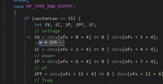
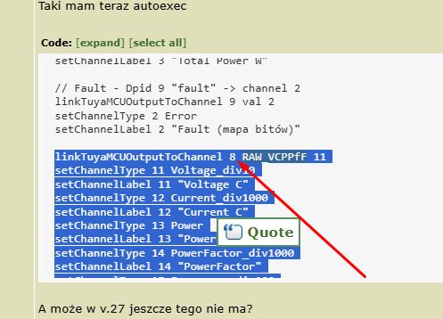
linkTuyaMCUOutputToChannel 113 RAW_VCPPfF 7
setChannelType 7 Voltage_div10
setChannelLabel 7 "Voltage L1"
setChannelType 8 Current_div1000
setChannelLabel 8 "Current L1"
setChannelType 9 Power_div10
setChannelLabel 9 "Power L1"
setChannelType 10 PowerFactor_div1000
setChannelLabel 10 "PowerFactor L1"
setChannelType 11 Frequency_div1000
setChannelLabel 11 "Frequency L1"

linkTuyaMCUOutputToChannel 114 RAW_VCPPfF 12
setChannelType 12 Voltage_div10
setChannelLabel 12 "Voltage L2"
setChannelType 13 Current_div1000
setChannelLabel 13 "Current L2"
setChannelType 14 Power_div10
setChannelLabel 14 "Power L2"
setChannelType 15 PowerFactor_div1000
setChannelLabel 15 "PowerFactor L2"
setChannelType 16 Frequency_div1000
setChannelLabel 16 "Frequency L2"

linkTuyaMCUOutputToChannel 115 RAW_VCPPfF 17
setChannelType 17 Voltage_div10
setChannelLabel 17 "Voltage L3"
setChannelType 18 Current_div1000
setChannelLabel 18 "Current L3"
setChannelType 19 Power_div10
setChannelLabel 19 "Power L3"
setChannelType 20 PowerFactor_div1000
setChannelLabel 20 "PowerFactor L3"
setChannelType 21 Frequency_div1000
setChannelLabel 21 "Frequency L3"

// Device temperature - Dpid 103 "Device temperature" -> channel 23
linkTuyaMCUOutputToChannel 103 val 23
setChannelType 23 Temperature
setChannelLabel 23 "Device temperature [C]"

// Leakage tripping - Dpid 15 "leakage_tripping" -> channel 24
linkTuyaMCUOutputToChannel 15 val 24
setChannelType 24 ReadOnly
setChannelLabel 24 "Earth Leakage value [mA]"

// Dpid 17 "Dpid 17" -> channel 25
linkTuyaMCUOutputToChannel 17 RAW 25
// setChannelType 25 ReadOnly
// setChannelLabel 25 "SETUP TempAlarm/Leakage Current dpID17"
// tuyaMcu_sendCmd 0x06 11000008050000550400001D - TempDevAL=DISABLED=85C, LeakageEarth alarm=DISABLED=29mA
// tuyaMcu_sendCmd 0x06 11000008050100410401001D - EANBLE TempDev=65C, EnableLE=29mA

// Alarm temperature - Dpid 118 "Power Factor L1 - or maby overall PF?" -> channel 26
// linkTuyaMCUOutputToChannel 118 val 26
// setChannelType 26 PowerFactor_div1000
// setChannelLabel 26 "Power Factor L1"

// Dpid 18 "Dpid 18" -> channel 27
linkTuyaMCUOutputToChannel 18 RAW 27
// setChannelType 27 ReadOnly
// setChannelLabel 27 "SETUP Dpid 18 SETUP_MaxP_MaxV_Min_V/UnbalanceC/Lack_of_Phase"
//
// uartSendHex 55AA00060018120000140101026203010109040100A0020000140500000077 - no 3Phase alarms
// uartSendHex 55AA00060018120000140101026203010109040100A0020100140501000078 -
// MaxCurrEN=63A,MaxVolEN=265V,MinVolEn=160V,inbalanced 3Phase current EN=20%,lack of Phase EN

//Delay to switch off by Under/Over Voltage - Dpid 123 "Delay to switch off by Under/Over Voltage" -> channel 31
linkTuyaMCUOutputToChannel 123 val 31
setChannelType 31 TextField
setChannelLabel 31 "SETUP Delay to switch off by Under/Over Voltage"

// Bad Voltage recovery time - Dpid 120 "Bad Voltage Recovery Time" -> channel 32
linkTuyaMCUOutputToChannel 120 val 32
setChannelType 32 TextField
setChannelLabel 32 "SETUP recovery time from bad Voltage [s]"

// Delay to switch off by Under/Over Current- Dpid 124 "Delay to switch off by Under/Over Current" -> channel 33
linkTuyaMCUOutputToChannel 124 val 33
setChannelType 33 TextField
setChannelLabel 33 "SETUP to switch off by Under/Over Current"

// Recovery time from Under/Over current - Dpid 121 "Recovery time from under/over current" -> channel 34
linkTuyaMCUOutputToChannel 121 val 34
setChannelType 34 TextField
setChannelLabel 34 "SETUP recovery time from under/over current"

// Dpid 131 "Dpid 131 - 0" -> channel 35
linkTuyaMCUOutputToChannel 131 val 35
setChannelType 35 ReadOnly
setChannelLabel 35 "How many times OverCurrent has triggered since startup"

// Dpid 127 "Dpid 127 - 0" -> channel 36
// linkTuyaMCUOutputToChannel 127 val 36
// setChannelType 36 ReadOnly
// setChannelLabel 36 "Is Load on L1/A (1=yes/0=no)"

// Dpid 128 "Dpid 128 - 0" -> channel 37
// linkTuyaMCUOutputToChannel 128 val 37
// setChannelType 37 ReadOnly
// setChannelLabel 37 "Is Load on L2/B (1=yes/0=no)"

// Dpid 129 "Dpid 129 - 0" -> channel 38
// linkTuyaMCUOutputToChannel 129 val 38
// setChannelType 38 ReadOnly
// setChannelLabel 38 "Is Load on L3/C (1=yes/0=no)"

// Dpid 136 "Dpid 136 - 1" -> channel 39 - for tests only
// linkTuyaMCUOutputToChannel 136 val 39
// setChannelType 39 TextField
// setChannelLabel 39 "SETUP Voltage multiplier RW Dpid 136=1"

// Dpid 137 "Dpid 137 - 1" -> channel 40 - for tests only
// linkTuyaMCUOutputToChannel 137 val 40
// setChannelType 40 TextField
// setChannelLabel 40 "SETUP Current multiplier RW Dpid 137=1"

// ______________________________________________ACCEPTED_________TILL_____THIS___LINE
//  Dpid 12 "Dpid 12 - 1" -> channel 43 Not quite if no load, 0 clear something
// linkTuyaMCUOutputToChannel 12 val 43
// setChannelType 43 ReadOnly
// setChannelLabel 43 "RO Dpid 12=1"

// Dpid 13 "Dpid 13 - 1" -> channel 44
// linkTuyaMCUOutputToChannel 13 val 44
// setChannelType 44 ReadOnly
// setChannelLabel 44 "RO Dpid 13=1"

// Dpid 102 "Dpid 102 - 30" -> channel 45
// linkTuyaMCUOutputToChannel 102 val 45
// setChannelType 45 TextField
// setChannelLabel 45 "RW Dpid 102=30"

// Dpid 104 "Dpid 104 - 1" -> channel 46
// linkTuyaMCUOutputToChannel 104 val 46
// setChannelType 46 ReadOnly
// setChannelLabel 46 "RO Dpid 104=1"

// Dpid 112 "Dpid 112 - 0" -> channel 47
// linkTuyaMCUOutputToChannel 112 val 47
// setChannelType 47 ReadOnly
// setChannelLabel 47 "RO Dpid 112=0"

// Dpid 122 "Dpid 122 - 20" -> channel 48
// Probably Lost Current Recovery Delay Time:1-9999s (Adjustable) (Default:20s) what it is???
// linkTuyaMCUOutputToChannel 122 val 48
// setChannelType 48 TextField
// setChannelLabel 48 "RW Dpid 122=20"

// "Dpid 125-10" -> channel 49
// Probably Time Threshold of Lost Flow Event:1-999s (Adjustable)(Default:10s) what it is???
// linkTuyaMCUOutputToChannel 125 val 49
// setChannelType 49 TextField
// setChannelLabel 49 "RW Dpid 125=10"

// Dpid 132 "Dpid 132 - 0" -> channel 50
// linkTuyaMCUOutputToChannel 132 val 50
// setChannelType 50 ReadOnly
// setChannelLabel 50 "RO Dpid 132=0"

// Dpid 133 "Dpid 133 - 0" -> channel 51
// linkTuyaMCUOutputToChannel 133 val 51
// setChannelType 51 ReadOnly
// setChannelLabel 51 "RO Dpid 133=0"

// Dpid 134 "Dpid 134 - 2" -> channel 52
// linkTuyaMCUOutputToChannel 134 val 52
// setChannelType 52 ReadOnly
// setChannelLabel 52 "RO Dpid 134=2"

// Dpid 135 "Dpid 135 - 0" -> channel 53
// linkTuyaMCUOutputToChannel 135 val 53
// setChannelType 53 TextField
// setChannelLabel 53 "RW Dpid 135=0"

// Dpid 105 "Dpid 105" -> channel 54
// linkTuyaMCUOutputToChannel 105 val 54
// setChannelType 54 ReadOnly
// setChannelLabel 54 "Dpid 105"

// Dpid 106 "Dpid 106" -> channel 55
// linkTuyaMCUOutputToChannel 106 val 55
// setChannelType 55 ReadOnly
// setChannelLabel 55 "Dpid 106 - j....EwAAAAAAAAAAAA=="

// Dpid 109 "Dpid 109" -> channel 56
// linkTuyaMCUOutputToChannel 109 val 56
// setChannelType 56 ReadOnly
// setChannelLabel 56 "Dpid 109 - AAA8"

// Dpid 109 "Dpid 117" -> channel 57
linkTuyaMCUOutputToChannel 117 RAW 57
// setChannelType 57 ReadOnly
// setChannelLabel 57 "Dpid 117-Probably scheduler"

waitFor NTPState 1 // wait for NTPState 1 second
tuyaMcu_sendCurTime //Send time to tuyaMCU

// every 30 seconds, request update from TuyaMCU
addRepeatingEvent 30 -1 tuyaMcu_sendQueryState
//tuyaMcu_sendQueryState
.
.
Fig. 2. Relay board, with measurement circuitry visible ReEnergy RN8302B .
 .
.
Fig. 3. Top view of the relays themselves, measuring coils on individual phases visible, neutral track not interrupted.
 .
.
Fig. 4. The other side of the relay board showing the power supply based on the circuit with the description "8231H Q24A1006"
 .
.
Fig. 5. Board with MCU CMS32L051 , display controller TM1622B , and 24C64 eeprom.
 .
.
Fig 6. The same board from a different angle visible circuit markings.
 .
.
Fig 7. The board with the display also visible buttons for operation.
 .
.
Fig. 8. CB3S WiFi communication module based on BK7231N chip (screen not removed).
 .
.
Figure 9: Relay including current leakage measurement coil.
 .
.
 .
.
Figure 10-11: Scan of instructions
Fig 12. A snapshot of the auction view.
The goodies have arrived thanks!
 .
.
Cool? Ranking DIY


