logo elektroda
logo elektroda
X
logo elektroda

Disassembling Generic US Tuya RMC003 Smart Plug with LN882HKI MCU and CNHZ HZ32-1A3S-LH Relay

divadiow 636 6
ADVERTISEMENT
  • Helpful post
    #1 21419808
    divadiow
    Level 34  
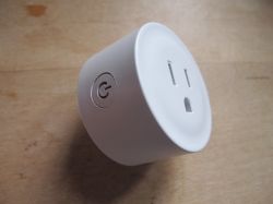
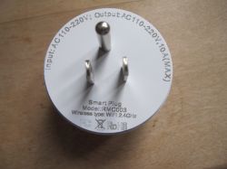
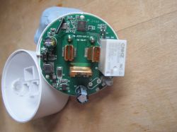
    Basic RMC003 US 110-220V smart plug with 10A CNHZ HZ32-1A3S-LH relay, no power monitoring, 1 blue LED and 1 button.

    Access was relatively easy - crushed the outer casing in a rubber-lined vice, just below the join rim, until there's cracking of the glue and gaps form for a spudger to then be inserted to complete the job.

    Pics:
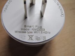
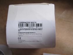
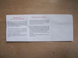
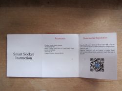
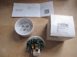
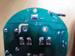
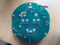
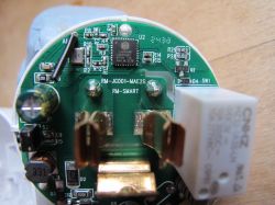
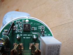
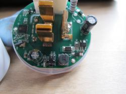
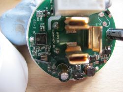
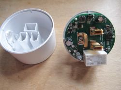
    Close-up of the bottom part of the RMC003 smart plug with model and wireless type inscriptions. White smart plug with a circular button on the side. Front of the RMC003 smart plug with visible prongs and inscriptions. Label with barcode and product information on a white box. Instructions for adding devices in Easy and AP mode Smart socket RMC001 instruction manual. Disassembled smart plug with instruction manual and packaging.PCB board with labeled solder points View of smart plug circuit board. Close-up of an opened smart plug showing a green PCB and electronic components. Close-up of the interior of a smart plug with visible PCB and Lightning Semi LN882HKI component. PCB of the RMC003 smart plug with Lightning Semi LN882HKI chip. Inner view of the RMC003 smart plug with visible components on the PCB. Close-up of a smart plug PCB labeled RM-JG001-MAE2G with electronic components. Interior of a smart plug showing the PCB and housing.

    Plug was from JSPTECH store on Ali Express https://www.aliexpress.com/item/1005007884742225.html
    US standard smart WiFi plug with JSPTEC logo and Alexa and Google Home compatibility.

    PCB print:
    RM-JG001-MAE2G
    RM-SMART

    The main MCU is a Lightning Semi LN882HKI -
    https://www.elektroda.com/rtvforum/topic4027545.html
    https://www.elektroda.com/rtvforum/topic4028087.html
    https://www.elektroda.com/rtvforum/topic4032240.html
    https://www.elektroda.com/rtvforum/topic4045532.html

    Unfortunately the pads to capture UART boot log (B9), get into flash mode (A9 grounded) and then flash/dump (A2, A3) are inaccessible until the main PCB is de-soldered from the power pins. For me this was quite destructive, melting the plastic surrounding the pins. It had to get too hot before the solder would melt. I did mix some 63/37 pb solder in first but I guess not enough.
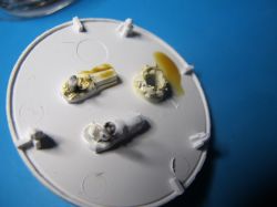
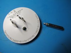
    Bottom view of a white plastic plug base with the casing removed. View of the RMC003 plug with visible back part and removed component.

    boot log @921600 baud from B9
    Code: Text
    Log in, to see the code


    TuyaOS SDK v3.5.4 like every other Tuya LN882H firmware we've captured to date. Version 1.0.0 - no OTA upgrade offered either, like all others.

    Code: Text
    Log in, to see the code


    Device schema e1k73cfg

    I wrote off the power pins and made this so device could be tested on mains
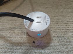
    Smart plug RMC003 with blue LED on a carpet.

    Tuya_3.5.4_RMC003_US_PLUG_(schemaID-e1k73cfg)_ONPCB_LN882H_1.0.0.bin firmware dump: https://github.com/openshwprojects/FlashDumps/tree/main/IoT/LN882H

    OBK template

    Code: JSON
    Log in, to see the code
  • ADVERTISEMENT
  • #2 21419866
    p.kaczmarek2
    Moderator Smart Home
    LN882H on PCB, that's nice, did you know in advance that it will be LN882H-based or was it just a lucky shot?

    It's a shame that Tuya uses non-isolated power supplies for such devices, otherwise it could be a very good candidate for DHT11/BMP280/anything weather sensor/station, but without mains isolation it could be risky... you could get live potential on DHT/DS18B20, etc.
    Helpful post? Buy me a coffee.
  • ADVERTISEMENT
  • #3 21419882
    divadiow
    Level 34  
    p.kaczmarek2 wrote:
    did you know in advance that it will be LN882H-based or was it just a lucky shot?


    Lucky shot. Just see what comes.

    p.kaczmarek2 wrote:
    It's a shame that Tuya uses non-isolated power supplies for such devices,


    :( what would you expect to see to know that there's isolation? How can you tell?
  • ADVERTISEMENT
  • Helpful post
    #4 21419913
    p.kaczmarek2
    Moderator Smart Home
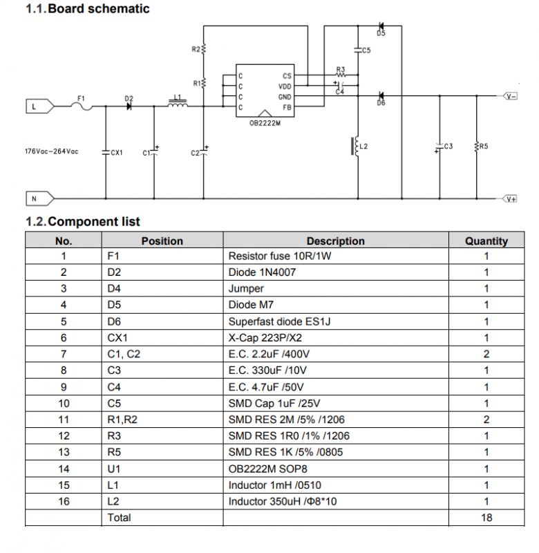
    This is non-isolated power supply, a step down converter:
    OB2222M power supply schematic with component list.
    For example, this one is done with OB2222MCP chip.
    On this schematic, you can see there is a continous line from mains N (or L, if you swap plug...) to the one of power supply output terminals. So, with this setup, you can sometimes get live potential on, let's say DHT11 ground. And then if you touch DHT11 ground with one hand, and, let's say, PC case with second hand, you'll get a serious shock.
    Sample device where it's used: https://www.elektroda.com/rtvforum/topic3828223.html


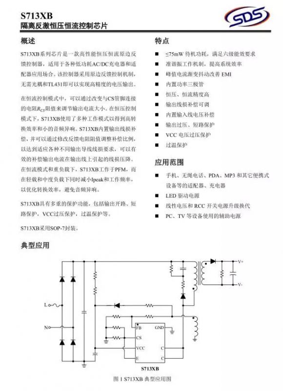
    And this is an isolated power supply, it's a flyback converter as usual. Very common topology, also used for 5V "chargers", etc:
    Flyback converter schematic with S713XB chip and text in Chinese.
    As you can see, there is no continous connection between mains (L or N) and the power supply output - it's isolated by transformer. So, unless a fault occurs, it's more safe than a non-isolated converter, but still caution is recommended.
    Sample device where it's used: https://www.elektroda.pl/rtvforum/topic4098965.html
    Helpful post? Buy me a coffee.
  • #5 21419922
    divadiow
    Level 34  
    very interesting. thank you.

    Added after 11 [minutes]:

    noticed earlier that the plug is marked as 110-220V. Our mains is typically 230-240v (going on the Atorch device reading when used - 241v today). I wonder if the 220 tolerance covers 230-240 or, if used in production, this device can be expected to fail after a short while

    Added after 3 [minutes]:

    relay does say 277vAC, black cap 400v and green cap 10v
  • #6 21419989
    p.kaczmarek2
    Moderator Smart Home
    You should check U1 for that. This is the most crucial element and it most likely tolerates higher voltages than 220V AC.

    Assuming that you still have it open, and if not, don't worry, it will be certainly ok.

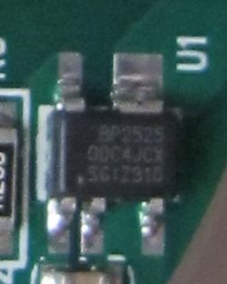
    \Wait, I seem to be able to read the marking on one of the photos - BP2525? https://www.elektroda.com/rtvforum/find.php?q=BP2525
    Helpful post? Buy me a coffee.
  • ADVERTISEMENT
  • #7 21420003
    divadiow
    Level 34  
    yes, BP2525
    Image of BP2525 integrated circuit on a printed circuit board.

    Code: Text
    Log in, to see the code

Topic summary

The discussion revolves around the disassembly of the Tuya RMC003 smart plug, which features a non-isolated power supply using the LN882HKI MCU and a CNHZ HZ32-1A3S-LH relay. The user successfully accessed the internal components by crushing the outer casing. Concerns were raised about the safety of using non-isolated power supplies, particularly regarding the risk of live potential on connected sensors. The power supply was identified as a step-down converter, with discussions on the implications of operating at higher voltages than specified. The BP2525 chip was confirmed to tolerate a voltage range of 85Vac to 265Vac, indicating its suitability for the plug's operational environment.
Summary generated by the language model.
ADVERTISEMENT