No-name AliExpress 3-phase EV charger (EVSE) with WBR3
Differences from:
https://www.elektroda.com/rtvforum/topic4085036.html#21754359 - this one does not have a connection to the electrical meter and is 3-phase
https://www.elektroda.com/rtvforum/topic4159907.html - this one is 3-phase
These are only pictures of the inside, without any software/MCU hacking. If this is not supposed to be here, please feel free to delete it.


what does SW1 seem to do:
1,2 - i do not understand exactly, but seem to switch between 8,10,13,16A and 16,20,24,32A modes for the button
3 - most likely 1/3 phase
4 - switches C and F and also switches the limit up to 40/50A - I guess as USA do not use 3 phases
there is no way to be able to set less then 8A out of box
ARM chip is
GigaDevice
GD32F303
RET6
FX0K596
A02515
https://download.gigadevice.com/Datasheet/GD32F303xx%20Datasheet%20Rev3.2.pdf
Identifies itself as GO-E31-32A in device scan
HEADER seems to be
PB11 Alternate: I2C1_SDA, USART2_RX
VCC
Header seems to be
DIO CLK GND VCC
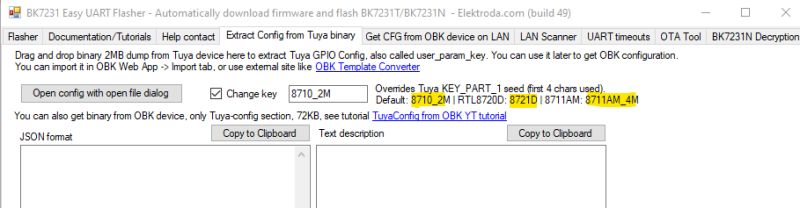
PIDS
Differences from:
https://www.elektroda.com/rtvforum/topic4085036.html#21754359 - this one does not have a connection to the electrical meter and is 3-phase
https://www.elektroda.com/rtvforum/topic4159907.html - this one is 3-phase
These are only pictures of the inside, without any software/MCU hacking. If this is not supposed to be here, please feel free to delete it.


what does SW1 seem to do:
1,2 - i do not understand exactly, but seem to switch between 8,10,13,16A and 16,20,24,32A modes for the button
3 - most likely 1/3 phase
4 - switches C and F and also switches the limit up to 40/50A - I guess as USA do not use 3 phases
there is no way to be able to set less then 8A out of box
ARM chip is
GigaDevice
GD32F303
RET6
FX0K596
A02515
https://download.gigadevice.com/Datasheet/GD32F303xx%20Datasheet%20Rev3.2.pdf
Identifies itself as GO-E31-32A in device scan
HEADER seems to be
PB11 Alternate: I2C1_SDA, USART2_RX
VCC
Header seems to be
DIO CLK GND VCC
PIDS
{"1":"Forward active power","3":"Device State","4":"Set current","6":"Phase A","7":"Cumulative power","8":"Phase C","9":"Device","10":"Fault","13":"Connection State","17":"Energy","18":"Open","19":"Schedule charging","24":"Temperature","25":"Once Charge Energy","28":"延时充电设置","33":"Charging operation","101":"Customize Scene","102":"Current Voltage","103":"Phase A Current","104":"Phase B voltage","105":"Phase C voltage","106":"Phase B Current","107":"Phase C Current","108":"Power","109":"Phase A voltage","110":"Time","111":"Cook Time","112":"SetDefineTime","113":"Timer Sync","114":"Time","115":"Target Time","116":"Charging Operation","117":"SetDelayTime","118":"状态","119":"RFID card enable"}