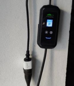
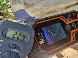
Teardown and OpenBeken drop in for Feyree Dynamic Load Balancing EVSE with Tuya App Function from Aliexpress Store. Decent quality device for the price. I purchased previous models by this vendor that worked well, so I was willing to take the risk with the TuyaMCU. Model F-OBZ2-AC-1P32 - this model isn't visible anywhere when purchasing.
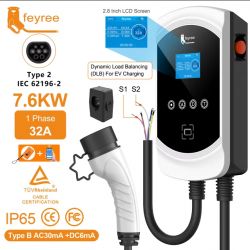
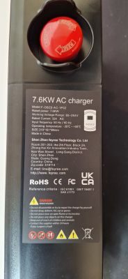
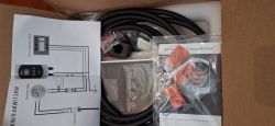
The goal for me was to be able to adjust the amps/power from MQTT or home assistant while EV charging is in progress. This can be done with OpenBeken.
Opening
Easy to open, with 8 screws covered by rubber seals. There was no warranty/security seal.
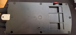
Device Overview
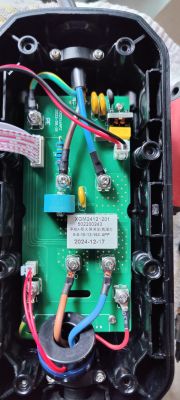
This particular charger is 240v, 32a single phase. It also has a secondary CT clamp on the input wiring end that can be extended to a distribution board.
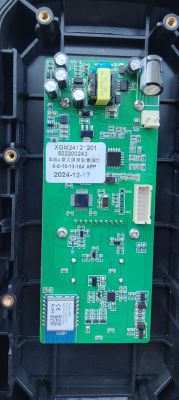
It consists of two main boards, the electrical relays (black), and the logic controller (white). The Logic controller had buttons and TFT screen on the other side. The device is advertised with RCD type B, but if it exists, likely implemented electronically. I have a dedicated RCD type B prior to this charger.
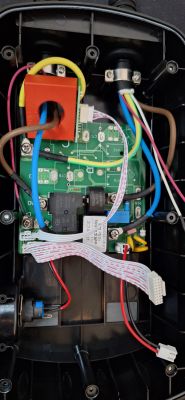
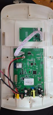
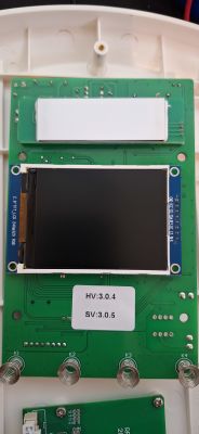
The EV charger is run by a GigaDevice GD32F303RCT6
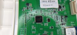
RN7302 metering chip.
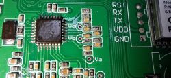
!!! IMPORTANT !!!
Do not attempt to tinker when plugged into mains. I recommend removing the logic board from the mains supply and power it with isolated bench supply with 3.3v or 12v from one of the relevant VDD headers.
Do not attempt to test, flash or capture with mains power applied without all equipment being electrically isolated... isolate all equipment; isolated USB and a disconnected/isolated laptop.
WBR3 Pins
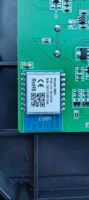
The logic board has a WBR3 Tuya chip, which was not supported by OpenBeken at the time of writing, but mostly pin compatible with others like CB3S. The now supported WBR3 flash process requires lifting the chip anyway, so replacing with a CB3S is probably still quicker if you have one around, otherwise follow the WBR3 flash process.
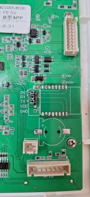
There is a nice looking header for accessing RX,TX, RST and GND of the WBR3, but be wary of the 12v on the VDD - Do NOT use this VDD point.
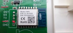
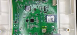
Replacing The WBR3 with CB3S
There are only 6 pins connected to the WBR3; GND, VCC, RX, TX, RST, and EN. EN (Pin3) has 3.3v applied for Enable (for ESP) - make sure you replace it with a chip that can handle 3.3v on PIN3, or cut the trace. I cut the trace for my purposes.
Traces visible with the WBR3 removed:
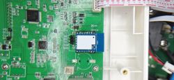
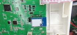
I chose to replace with a CB3S pre-flashed with OpenBeken since it is mostly pin compatible and I had a few spare. Though I destroyed a WB3S in the process - I suspect because of the 3.3v Enable pin. I made a dirty pin header so I could quickly replace chips, Since I was capturing and testing, . If anyone knows of a nice test frame intermediate board that could be soldered on top, let me know!
Tuya App and TuyaMCU Capture and Configuration
!!!IMPORTANT!!!
Do not attempt to flash or connect to RX/TX for capturing while on mains power without isolated power at every level. I used a isolated inverter, isolated USB adapter, and laptop running on battery for capturing.
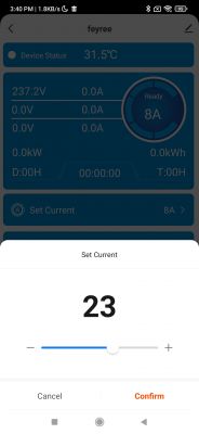
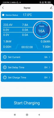
Example of the parameters in in the Tuya App, and adjusting the Charge Amps.
I used the TuyaMCU Analyzer tool for capturing.
Here are some of the capture files:
and the data model JSON collected from the tuya developer:
Table of interesting dpids. Covers the core features:
Observations about the string type dpIDs:
Cases where TuyaMCU send actual strings (not just strings to be cast as int or float) seems to be quite rare, and handling dpIDs of this type will be a challenge.
Observation about the CT Clamp:
The external CT clamp meant for import smoothing does not appear to be integrated with the TuyaMCU communications from the capture, even though the dpId data model makes reference to it. Even so, it's not entirely clear how the CT balancing is meant to work in conjunction with the app. For me this is not a issue, as I want to control the Amps via OpenBeken+MQTT and I'm not using the external CT clamp. Power consumption from EV charging is tracked independently by an internal sensor.
Observations about setting amp limit on dpID 115:
Through the Tuya app and screen, the minimum is 8 amps. However, through TuyaMCU, this can be set as low as 6amps on my EV. However, after a session set to 6 amp and unplugging and plugging back in to start a new charge session, this resets to 20. This value is full integer only, no floats.
OpenBeken Configuration
config json - there are no pins, just basic startup command. The rest is in the autoexec.bat below
autoexec.bat
Below are the autoexec mappings I've settled on. So far I can do what I set out to do, which is turn on the charging with dpID 124=0 and setting the charging amps with dpID 115.
Note about some fields:
* String types from TuyaMCU; There does not appear to be a setChannelType compatible with linkTuyaMCUOutputToChannel [id] str [ch]. i.e. channels can't handle string types. I experimented with linkTuyaMCUOutputToChannel MQTT which does pass the string through to MQTT, but appears to be just for testing. The strings do appear in /cm?cmnd=DP if the TuyaMCU flag 47 is used.
- Updated to use Enum Types with SetChannelEnum from this PR
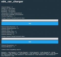
now with SetChannelEnum we can map tuyaMCU enum types all the way to homeassistant via discovery. That makes initialising charging much easier. This is what it looks like:
![[WBR3] Feyree EV Charger teardown with adjustable charging via TuyaMCU [WBR3] Feyree EV Charger teardown with adjustable charging via TuyaMCU](https://obrazki.elektroda.pl/2464589600_1760413364_thumb.jpg)
![[WBR3] Feyree EV Charger teardown with adjustable charging via TuyaMCU [WBR3] Feyree EV Charger teardown with adjustable charging via TuyaMCU](https://obrazki.elektroda.pl/8718418200_1760413366_thumb.jpg)
![[WBR3] Feyree EV Charger teardown with adjustable charging via TuyaMCU [WBR3] Feyree EV Charger teardown with adjustable charging via TuyaMCU](https://obrazki.elektroda.pl/5704213000_1760413368_thumb.jpg)
Note the quirks from the MCU, this is charging at 20A with max capability set to 32A. When set to 32A, the 16a field is not used (but does update between 1-16 if you change the 32A field). Also, the 'Charge Command' always goes back to 'Ready for Command' state after accepting a command. And the 'Switch' seems to not make any difference.


The goal for me was to be able to adjust the amps/power from MQTT or home assistant while EV charging is in progress. This can be done with OpenBeken.
Opening
Easy to open, with 8 screws covered by rubber seals. There was no warranty/security seal.

Device Overview
This particular charger is 240v, 32a single phase. It also has a secondary CT clamp on the input wiring end that can be extended to a distribution board.
It consists of two main boards, the electrical relays (black), and the logic controller (white). The Logic controller had buttons and TFT screen on the other side. The device is advertised with RCD type B, but if it exists, likely implemented electronically. I have a dedicated RCD type B prior to this charger.


The EV charger is run by a GigaDevice GD32F303RCT6

RN7302 metering chip.

!!! IMPORTANT !!!
Do not attempt to tinker when plugged into mains. I recommend removing the logic board from the mains supply and power it with isolated bench supply with 3.3v or 12v from one of the relevant VDD headers.
Do not attempt to test, flash or capture with mains power applied without all equipment being electrically isolated... isolate all equipment; isolated USB and a disconnected/isolated laptop.
WBR3 Pins
The logic board has a WBR3 Tuya chip, which was not supported by OpenBeken at the time of writing, but mostly pin compatible with others like CB3S. The now supported WBR3 flash process requires lifting the chip anyway, so replacing with a CB3S is probably still quicker if you have one around, otherwise follow the WBR3 flash process.
There is a nice looking header for accessing RX,TX, RST and GND of the WBR3, but be wary of the 12v on the VDD - Do NOT use this VDD point.


Replacing The WBR3 with CB3S
There are only 6 pins connected to the WBR3; GND, VCC, RX, TX, RST, and EN. EN (Pin3) has 3.3v applied for Enable (for ESP) - make sure you replace it with a chip that can handle 3.3v on PIN3, or cut the trace. I cut the trace for my purposes.
Traces visible with the WBR3 removed:

I chose to replace with a CB3S pre-flashed with OpenBeken since it is mostly pin compatible and I had a few spare. Though I destroyed a WB3S in the process - I suspect because of the 3.3v Enable pin. I made a dirty pin header so I could quickly replace chips, Since I was capturing and testing, . If anyone knows of a nice test frame intermediate board that could be soldered on top, let me know!


Tuya App and TuyaMCU Capture and Configuration
!!!IMPORTANT!!!
Do not attempt to flash or connect to RX/TX for capturing while on mains power without isolated power at every level. I used a isolated inverter, isolated USB adapter, and laptop running on battery for capturing.
Example of the parameters in in the Tuya App, and adjusting the Charge Amps.


I used the TuyaMCU Analyzer tool for capturing.
Here are some of the capture files:
and the data model JSON collected from the tuya developer:
Code: JSON
Table of interesting dpids. Covers the core features:
| Tuya dpID | type | notes: value | 10 | bitmap | Fault Alarm: [err_leak,err_cp, err_temp, warn_a_uvp, warn_b_uvp,warn_c_uvp,err_a_ovp,err_b_ovp,err_c_ovp,err_ocp,err_10,err_11,err_esb,warn_for_sck,err_leak_sck,err_on] | 14 | enum | RW working mode: [0=charge_now, 1=charge_pct, 2=charge_energy, 3=charge_scheduled] | 18 | bool | RW switch: on/off | 101 | enum | Status: [0=not connected, 1=connected, 2=charging, 3=waiting on rfid, 4=finished, 5=wait for charging, 6=error] | 102-104 | val | voltage /10 - 3 id's, one for each phase, 102 Ph1 | 105-107 | val | amps /10 - 3 id's, one for each phase, 105 Ph1 | 109 | val | Power in kW /10 | 110 | val | Temperature /10 | 112 | val | Session kWh /10 | 113 | enum | Maximum supported current: [0=maximum 16a, 1=maximum 32a] | 120 | str | time counter; delay timer countdown, or charge run time counter - string like: 08:00:00 | 114 | val | RW Set Max Charge Amps when dpid 113 = 16a enum type | 115 | val | RW Set Max Charge Amps when dpid 113 = 32a enum type | 125 | val | RW Set Max Charge Amps when dpid 113 = 60a enum type | 118 | val | RW delay time command | 122 | str | delay time state - string like: D:08H | 119 | val | RW charge time command | 121 | str | charge time state: T:13H | 124 | enum | RW Charge Command: [0=charging,1=charging stopped, 3=waiting for delay] Response: [10=charging stopped,255=?] |
Observations about the string type dpIDs:
Cases where TuyaMCU send actual strings (not just strings to be cast as int or float) seems to be quite rare, and handling dpIDs of this type will be a challenge.
Observation about the CT Clamp:
The external CT clamp meant for import smoothing does not appear to be integrated with the TuyaMCU communications from the capture, even though the dpId data model makes reference to it. Even so, it's not entirely clear how the CT balancing is meant to work in conjunction with the app. For me this is not a issue, as I want to control the Amps via OpenBeken+MQTT and I'm not using the external CT clamp. Power consumption from EV charging is tracked independently by an internal sensor.
Observations about setting amp limit on dpID 115:
Through the Tuya app and screen, the minimum is 8 amps. However, through TuyaMCU, this can be set as low as 6amps on my EV. However, after a session set to 6 amp and unplugging and plugging back in to start a new charge session, this resets to 20. This value is full integer only, no floats.
OpenBeken Configuration

config json - there are no pins, just basic startup command. The rest is in the autoexec.bat below
Code: JSON
autoexec.bat
Below are the autoexec mappings I've settled on. So far I can do what I set out to do, which is turn on the charging with dpID 124=0 and setting the charging amps with dpID 115.
Note about some fields:
* String types from TuyaMCU; There does not appear to be a setChannelType compatible with linkTuyaMCUOutputToChannel [id] str [ch]. i.e. channels can't handle string types. I experimented with linkTuyaMCUOutputToChannel MQTT which does pass the string through to MQTT, but appears to be just for testing. The strings do appear in /cm?cmnd=DP if the TuyaMCU flag 47 is used.
- Updated to use Enum Types with SetChannelEnum from this PR
now with SetChannelEnum we can map tuyaMCU enum types all the way to homeassistant via discovery. That makes initialising charging much easier. This is what it looks like:
![[WBR3] Feyree EV Charger teardown with adjustable charging via TuyaMCU [WBR3] Feyree EV Charger teardown with adjustable charging via TuyaMCU](https://obrazki.elektroda.pl/2464589600_1760413364_thumb.jpg)
![[WBR3] Feyree EV Charger teardown with adjustable charging via TuyaMCU [WBR3] Feyree EV Charger teardown with adjustable charging via TuyaMCU](https://obrazki.elektroda.pl/8718418200_1760413366_thumb.jpg)
![[WBR3] Feyree EV Charger teardown with adjustable charging via TuyaMCU [WBR3] Feyree EV Charger teardown with adjustable charging via TuyaMCU](https://obrazki.elektroda.pl/5704213000_1760413368_thumb.jpg)
Note the quirks from the MCU, this is charging at 20A with max capability set to 32A. When set to 32A, the 16a field is not used (but does update between 1-16 if you change the 32A field). Also, the 'Charge Command' always goes back to 'Ready for Command' state after accepting a command. And the 'Switch' seems to not make any difference.
Code: Text



![[WBR3] Feyree EV Charger teardown with adjustable charging via TuyaMCU [WBR3] Feyree EV Charger teardown with adjustable charging via TuyaMCU](https://obrazki.elektroda.pl/5684694700_1751933125_thumb.jpg)
