logo elektroda
logo elektroda
X
logo elektroda
Dostępna jest polska wersja

Czy wolisz polską wersję strony elektroda?

Nie, dziękuję Przekieruj mnie tam

TL;DR

  • A DIY micro tower combines a radio, spectrum visualizer, and amplifier in two compact desktop enclosures.
  • The radio uses ESP32S3, a 2.8-inch IPS display, MPR121 touch sensing behind 4 mm tinted glass, and encoder-based station browsing.
  • The units measure 200x61x130 mm for the radio and 200x40x130 mm for the spectrum and amplifier sections.
  • The spectrum runs on an ESP32 using both cores, refreshing two 1.9-inch IPS displays at 37 to 41 FPS.
  • The amplifier is not hi-fi, uses a TPA3110 module and AVT kit 2132 tone control, and the station list is stored rigidly in firmware.
Summary generated by AI based on the discussion content.
ADVERTISEMENT
Treść została przetłumaczona polish » english Zobacz oryginalną wersję tematu
📢 Listen (AI):
  • #121 21907033
    erni750906
    Level 8  
    Posts: 10
    heyk after downloading the spectrum file, opening it in an arduino program and releasing it for verification, it gives errors
  • ADVERTISEMENT
  • #122 21907037
    wieh76
    Level 12  
    Posts: 57
    Rate: 23
    I also got an error. It turned out that the TFT_eSPI library is too new for core 1.0.4. After installing version 2.4.79 the verification went positive. Whether it works I don't know because I only verified(waiting for parts) 🙂 Maybe it's the same for you.
  • #123 21907041
    efi222
    Level 22  
    Posts: 773
    Help: 12
    Rate: 1212
    The compilation conditions are given at the beginning of the source file:)
    If there are Tft_espi problems with the core version of ESP32 1.0.4
    I suggest changing the entry in the library directory:
    ... Processors/Tft_espi.h
    Comment out the entry #hal/gpio_11.h
  • #124 21907042
    erni750906
    Level 8  
    Posts: 10
    >>21907037 a tell me through which ardu you upload which version ba I version 2.3.6
  • #125 21907049
    efi222
    Level 22  
    Posts: 773
    Help: 12
    Rate: 1212
    >>21907042
    What error does it throw?
  • Missing hal/gpio_ll.h in TFT_eSPI ESP32 build

    #126 21907051
    wieh76
    Level 12  
    Posts: 57
    Rate: 23
    >>21907042 I have the latest 2.3.8 . efi222 I have seen🙂 but it was giving errors. I was prompted by gpt chat, as I say I haven't checked if it works because I don't currently have anything to use it on, but verification passes. Now for a test I updated to the latest and here is the error:
    Quote:
    In file included from /home/wiesiek/Arduino/libraries/TFT_eSPI/TFT_eSPI.h:101:0,
    from /home/wiek/Desktop/mikro_widmo_A1/mikro_widmo_A1.ino:8:
    /home/wiesiek/Arduino/libraries/TFT_eSPI/Processors/TFT_eSPI_ESP32.h:14:25: fatal error: hal/gpio_ll.h: No such file or directory
    compilation terminated.
    exit status 1

    Compilation error: exit status 1
  • #127 21907056
    efi222
    Level 22  
    Posts: 773
    Help: 12
    Rate: 1212
    efi222 wrote:
    If there are Tft_espi problems with core ESP32 version 1.0.4
    I suggest changing the entry in the library directory:
    ... Processors/Tft_espi.h
    Comment out the entry #hal/gpio_11.h

    Should make things easier
  • ESP32 core API mismatch causing compile errors

    #128 21907060
    erni750906
    Level 8  
    Posts: 10
    Such errors have popped up


    'FS' was not declared in this scope; did you mean 'fs::FS'?
    227 | typedef std::function<String(FS &fs, const String &fName)> ETagFunction;
    | ^~
    | fs::FS


    87 | class FS {
    | ^~
    'FS' was not declared in this scope; did you mean 'fs::FS'?
    227 | typedef std::function<String(FS &fs, const String &fName)> ETagFunction;
    | ^~
    | fs::FS
    C:³³³³AppData³³³ LocalArduino15³³³ Files³³³32³hardware/FS.h:87:7: note: 'fs::FS' declared here
    87 | class FS {
    | ^~

    227 | typedef std::function<String(FS &fs, const String &fName)> ETagFunction;
    | ^
    C:³³³³AppDataLocalArduino15packages32hardware3.3.8³³brariesWebServer/WebServer.h:227:16: error: '<expression error>' in namespace 'std' does not name a type
    227 | typedef std::function<String(FS &fs, const String &fName)> ETagFunction;
    | ^~~~~~~~~~~~~~~~~~~~~~~~~~~~~~~~~~~~~~~~~~~~~
    C:³³³³AppData³³³ocalArduino15packages³³³hardware³³³3.3.8³³braries/WebServer.h:228:32: error: 'ETagFunction' has not been declared
    228 | void enableETag(bool enable, ETagFunction fn = nullptr);
    | ^~~~~~~~~~~~
    C:³³³³AppData³³³ocalArduino15packages³³³hardware³³³3.3.8³³brariesWebServer/WebServer.h:245:3: error: 'ETagFunction' does not name a type; did you mean 'TaskFunction_t'?
    245 | ETagFunction _eTagFunction = nullptr;
    | ^~~~~~~~~~~~
    | TaskFunction_t
    C:³³³³AppData³³³ocalArduino15³³³packages32³³³hardware3.3.8³³braries/WebServer.h:228:50: error: could not convert 'nullptr' from 'std::nullptr_t' to 'int'
    228 | void enableETag(bool enable, ETagFunction fn = nullptr);
    | ^~~~~~~
    | |
    | std::nullptr_t


    56 | My_timer = timerBegin(0, 80, true);
    | ~~~~~~~~~~^~~~~~~~~~~~~


    35 | hw_timer_t *timerBegin(uint32_t frequency);
    | ^~~~~~~~~~

    57 | timerAttachInterrupt(My_timer, &onTimer, true);
    | ~~~~~~~~~~~~~~~~~~~~^~~~~~~~~~~~~~~~~~~~~~~~~~
    C:³³³³AppData³³³ocalArduino15³³³³³ware³³³3.3.8³³³/esp32-hal-timer.h:50:6: note: declared here
    50 | void timerAttachInterrupt(hw_timer_t *timer, void (*userFunc)(void));
    | ^~~~~~~~~~~~~~~~~~~~
    'timerAlarmWrite' was not declared in this scope; did you mean 'timerWrite'?
    58 | timerAlarmWrite(My_timer, timer_div, true ); //32kHz
    | ^~~~~~~~~~~~~~~
    | timerWrite
    C:³³³³³³³³.ino:59:3: error: 'timerAlarmEnable' was not declared in this scope; did you mean 'timerAlarm'?
    59 | timerAlarmEnable(My_timer);
    | ^~~~~~~~~~~~~~~~
    | timerAlarm

    exit status 1

    Compilation error: too many arguments to function 'hw_timer_t* timerBegin(uint32_t)'
  • ADVERTISEMENT
  • #129 21907062
    efi222
    Level 22  
    Posts: 773
    Help: 12
    Rate: 1212
    And have you downgraded the ESP32 core version to version 1.0.4?
    You have core version 3.3.8
  • #130 21907067
    wieh76
    Level 12  
    Posts: 57
    Rate: 23
    efi222 sorry I didn't notice this post. I have another question because I had to comment out one eeprom library (#include "eeprom.h) because I was also getting errors popping up. Does it have the right to work this way? I'm sitting on linux and the chat mentioned wrote to comment this one out because linux is case sensitive in code and hence the errors.
  • ADVERTISEMENT
  • #131 21907073
    erni750906
    Level 8  
    Posts: 10
    How's it going gentlemen, can anyone help how to bite it.

    Added after 1 [minute]:

    No, I haven't changed, but I'm already reinstalling.
  • TFT_eSPI setup file must be copied to root

    #132 21907075
    efi222
    Level 22  
    Posts: 773
    Help: 12
    Rate: 1212
    @wieh76
    I'll try compiling without this "eeprom.h" today and let you know the results.

    There is one more issue.
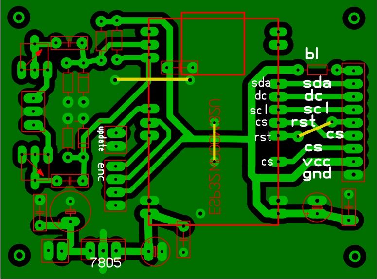
    There is a directory SETUP_TFT_ESPI in the spectrum source directory. Inside it is the file "User_Setup". This is the settings for the display driver and the SPI bus. This file needs to be copied to the root directory of the TFT_espi library and swapped with the original. Just archive the original somewhere before swapping.
    I think I'll do some additional description in the article.
    TFT_espi is not one of the very friendly ones.... :) (But for that, it drives "like a little car" :D ).
  • #133 21907084
    wieh76
    Level 12  
    Posts: 57
    Rate: 23
    >>21907075 I don't know maybe it's linux😀's fault. There are two of these libraries there which is why I ask. As for the description, it would be useful because I didn't know about the swap or didn't read about it. And the analyzer "nice" great thanks for the work and the project.
  • #134 21907090
    erni750906
    Level 8  
    Posts: 10
    Changing the core helped and it even uploaded to the esp only nothing is displayed because the author uploaded directly to the esp and I uploaded to the development board, I connected the pins as in the diagram but nothing is on the display.
  • Encoder pin mismatch in variables.h and schematic

    #135 21907099
    pepepe1
    Level 13  
    Posts: 77
    Rate: 128
    If you don't mind: at my place the combo went. Esp32D in 30 pin module, memory settings standard, Arduino version as recommended, Esp32 Espressif 2.0.17 board definitions and in addition in preferences
    h t t p s ://raw.githubusercontent.com/espressif/arduino-esp32/gh-pages/package_esp32_index.json.
    "From the package" there is still an encoder mismatch: in variables.h gpio 25 and 26, in the schematic 25 and 27. The board a little improved compared to my first version - this encoder + stabilizer, you can assemble or not.

    A revelation, thanks and greetings to the Author.

    DIY micro tower (desktop version)

    DIY micro tower (desktop version)
  • ESP32 core 2.0.17 limits spectrum bandwidth to 10 kHz

    #136 21907102
    efi222
    Level 22  
    Posts: 773
    Help: 12
    Rate: 1212
    @erni750906
    efi222 wrote:
    In the folder with the spectrum source is the folder SETUP_TFT_ESPI. Inside is the file "User_Setup". These are the settings for the display driver and the SPI bus. This file needs to be copied to the root directory of the TFT_espi library and swapped with the original. Just archive the original somewhere before swapping.
    I think I'll do some additional description in the article.
    TFT_espi is not one of the very friendly ones...

    Have you done this?

    Added after 7 [minutes]:

    pepepe1 wrote:
    Springs Esp32 Espressif 2.0.17

    With such a Core the bandwidth processed is 10kHz max
    The bandwidth on the spectrum is only up to 10kHz.
    There should be a version 1.0.4

    Added after 5 [minutes]:

    pepepe1 wrote:
    Springs Esp32 Espressif 2.0.17

    With such a Core the bandwidth processed is 10kHz max
    The bandwidth on the spectrum is only up to 10kHz.
    I don't even know if not less
    There should be a version 1.0.4
  • #137 21907125
    erni750906
    Level 8  
    Posts: 10
    I'm already doing it, I had a little problem with the electricity at home.

    Added after 4 [minutes]:

    And I am to understand that the connection of the ESP vs the displays is to be connected according to the file I am swapping.

    Added after 2 [minutes]:
    It has started up and is working, I still need to connect the encoder.
  • ADVERTISEMENT
  • #138 21907130
    efi222
    Level 22  
    Posts: 773
    Help: 12
    Rate: 1212
    erni750906 wrote:
    and I understand that the esp connection and the displays are to be connected according to the file that I am replacing

    Or with the diagram. Only there is an encoder connection error on the schematic. It should be on IO25 and IO26
  • #139 21907139
    erni750906
    Level 8  
    Posts: 10
    and tell me, because I have an encoder with the designation s1 s2 key and power supply, how in this situation s1 under 25 s2 under26 key under gnd

    Moderated By ArturAVS:

    3.1.13. Publish entries that violate the Polish language spelling rules, are careless and incomprehensible.

  • #140 21907141
    erni750906
    Level 8  
    Posts: 10
    ok the encoder has gone in without connecting the key


    Moderated By ArturAVS:

    3.1.13. Publish posts that violate Polish spelling rules, are careless and incomprehensible.

  • #141 21907147
    efi222
    Level 22  
    Posts: 773
    Help: 12
    Rate: 1212
    pepepe1 wrote:
    Board slightly improved compared to the prototype - this encoder + stabilizer, you can mount or not.

    I don't recall sharing the PCB :)
  • #142 21907149
    erni750906
    Level 8  
    Posts: 10
    efi222
    Thank you very much for the hints I am still taking on the preamplifiers and I will enjoy your awesome project and I will still ask you for the print file as of course you can total all 3 print files but this I will write right away on private

    Moderated By ArturAVS:

    3.1.13. Publish posts that violate the rules of Polish language spelling, careless and incomprehensible.

  • TFT_eSPI user_setup change caused compile error

    #143 21907159
    pepepe1
    Level 13  
    Posts: 77
    Rate: 128
    Something's up - a 1 kHz sine from the generator gave a bar between 6 and 8 kHz :) On core 1.0.4, with TFT_eSPI in the recommended version, changing the user_setup in the library folder and it threw an error:


    No such file or directory
    compilation terminated.

    I'll play around some more.

    Added after 5 [minutes]:

    efi222 wrote:
    pepepe1 wrote:
    Board slightly improved compared to prototype - this encoder + stabilizer, can be mounted or not.

    I don't recall making the PCB available.:)


    A mental abbreviation - obviously did not mean "prototype" (first copy by colleague efi222). Sorry, and already corrected :)
  • #144 21907172
    efi222
    Level 22  
    Posts: 773
    Help: 12
    Rate: 1212
    @pepepe1
    efi222 wrote:
    If there are Tft_espi problems with core ESP32 version 1.0.4
    I suggest changing the entry in the TFT_espi library directory:
    ... Processors/Tft_espi.h
    Comment out the entry #hal/gpio_11.h

    Should make things easier
  • #145 21907195
    pepepe1
    Level 13  
    Posts: 77
    Rate: 128
    This has solved the problem. Thank you very much for your help.
  • #146 21907200
    efi222
    Level 22  
    Posts: 773
    Help: 12
    Rate: 1212
    I have updated the title post. I have included some tips at the bottom to make it easier to run the spectrum.
  • Right speaker polarity error causes phase cancellation

    #147 21907323
    tytka
    Level 23  
    Posts: 763
    Help: 8
    Rate: 1840
    @efi222 And have you corrected this error with the polarity of the right speaker?
    If you leave it as the Chinaman described, then you have the right channel connected in counter-phase. And given that at low frequencies, there are always negligible phase shifts between the channels, they cancel each other out with such a connection, resulting in a heavily muted listening experience.
    If you connect it correctly, as I wrote, you will hear what the difference is.
  • Reversed right speaker polarity improved stereo image

    #148 21907328
    efi222
    Level 22  
    Posts: 773
    Help: 12
    Rate: 1212
    wieh76 wrote:
    I had to comment out one eeprom library (#include "eeprom.h) because errors were also popping up. Does it have the right to work this way?

    I've checked the compilation without this eeprom.h. It compiles correctly and the spectrum works.

    Added after 3 [minutes]:

    tytka wrote:
    Are you correcting this error with the polarity of the right speaker?

    I plugged the speaker in reverse temporarily. I must say that the stereo space and overall sound has improved. Thanks again :)
  • #149 21907390
    tytka
    Level 23  
    Posts: 763
    Help: 8
    Rate: 1840
    efi222 wrote:
    I have to say that the stereo space has improved
    It must have improved because, after all, by having one speaker in counter-phase, the audible space was severely distorted. As is well known, phase differences play a big part in this aspect. :)
  • Wireless firmware update via ESP AP mode

    #150 21908843
    efi222
    Level 22  
    Posts: 773
    Help: 12
    Rate: 1212
    Another previously undescribed feature regarding spectrum:
    Wireless software update (*.bin).
    After holding down the "update" button for about 3 seconds, the display will show that the ESP has "entered" AP mode.
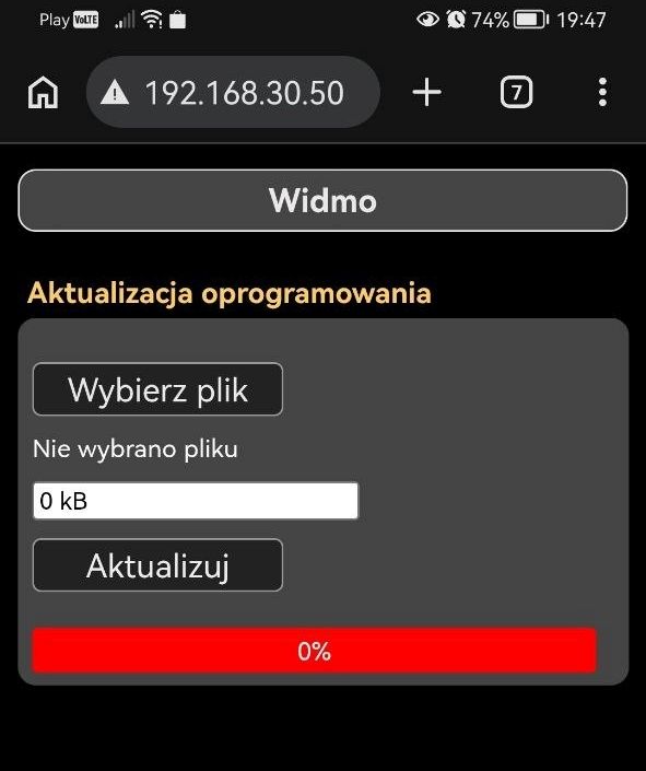
    You need to log in to the specified Wi-Fi access point " micro_widmo " - password: 12345678
    After logging in (ignore the message about no internet if it appears), you need to enter the IP 192.168.30.50 in your web browser
    The web page should launch.
    If AP mode has been running for a long time, I recommend refreshing the page before updating.
    This option is a little test version (working).

    Phone screen showing “Widmo” firmware update page at 192.168.30.50 with file upload and 0% progress bar
📢 Listen (AI):

FAQ

TL;DR: To FAQ dla osób budujących biurkową mikro wieżę DIY: front z 4 mm szkła, trzy moduły i obsługa, która „działa bardzo komfortowo”. Wyjaśnia, jak uruchomić radio i widmo na ESP32, jak zrobić dotyk przez przyciemniane szkło oraz jak uniknąć typowych błędów z TFT_eSPI, pinami i polaryzacją głośników. [#21903418]

Dlaczego to ważne: Ten wątek pokazuje nie tylko efektowną obudowę, ale też praktyczne rozwiązania problemów, które zwykle zatrzymują podobne projekty: dotyk przez szkło, kompilację starego core ESP32, OTA i błędy okablowania.

Obszar Zastosowane rozwiązanie Dlaczego właśnie to
Panel radia MPR121 + szkło 4 mm Obsługa podświetlanych pól dotykowych za szkłem
Przyciski wzmacniacza TTP223 Działały tam, gdzie patent z MPR121 i PLA się nie sprawdził
Końcówka mocy gotowy moduł TPA3110 Mała, prosta i wystarczająca do biurkowej mikro wieży

Najważniejszy wniosek: Najtrudniejsze w tym projekcie nie było samo ESP32, lecz dopracowanie integracji: czułości dotyku, zgodności bibliotek, mapowania GPIO i detali mechanicznych. Gdy te cztery rzeczy są poprawne, reszta składa się przewidywalnie.

Quick Facts

  • Wymiary modułów są typowo biurkowe: radio 200 × 61 × 130 mm, a widmo ze wzmacniaczem 200 × 40 × 130 mm. To pozwoliło utrzymać kompaktową, lekką konstrukcję. [#21899218]
  • Zasilanie jest rozdzielone: wzmacniacz pracuje z zewnętrznego zasilacza 12 V / 2 A, a pozostałe moduły dostają 5 V USB-C z jego wyjścia. [#21899218]
  • Dotyk przez szkło działa na polach o wymiarach 17 × 9 mm z przerwą 2 mm, ale wymaga zwiększonej czułości i dobrego dociśnięcia elektrod do szyby. [#21899490]
  • Widmo odświeża oba wyświetlacze z szybkością około 37–41 Hz, używając obu rdzeni ESP32 do próbkowania ADC i FFT. [#21899218]
  • Cała wieża waży około 1,3 kg, dlatego autor zrezygnował z wciskanego przycisku enkodera; nacisk przesuwałby urządzenie po biurku. [#21903418]

1. Jak wykonano przydymiony front szklany dla radia ESP32 i dlaczego wybrano szkło „anisol black” 4 mm zamiast pleksi?

Front wykonano z przyciemnianego szkła „anisol black” 4 mm, a panel maskujący to wydruk przyklejony samoprzylepną folią do gładkiej powierzchni szkła. Autor wybrał szkło zamiast pleksi, bo pleksi z czasem się rysuje, a szkło zachowuje „połysk szkła” i lepiej wygląda na froncie urządzenia. Krawędzie nie muszą być idealnie szlifowane, bo w tej konstrukcji są ukryte; autor często tylko je tępi papierem ściernym. [#21900849]

2. Jakie modyfikacje były potrzebne w bibliotece Adafruit_MPR121, aby przyciski dotykowe działały niezawodnie przez przyciemniane szkło 4 mm?

Trzeba było zwiększyć czułość biblioteki Adafruit_MPR121 i uruchamiać autokalibrację pól przy starcie programu. Autor udostępnił zmodyfikowaną bibliotekę w katalogu src/Adafruit_MPR121 i zaznaczył, że domyślne ustawienia były zbyt mało czułe dla szkła 4 mm. Dodatkowo pola mają 17 × 9 mm, odstęp 2 mm i muszą ściśle przylegać do szyby, bo luźne ułożenie pogarsza wykrywanie dotyku. [#21899490]

3. Dlaczego autor użył MPR121 w panelu radia i modułów TTP223 do przycisków wzmacniacza zamiast jednego rozwiązania dotykowego wszędzie?

Bo oba miejsca miały inne wymagania mechaniczne i optyczne. MPR121 sprawdził się w radiu za szkłem, gdzie potrzebne były podświetlane pola dotykowe. TTP223 zastosowano w selektorze wejść wzmacniacza i włączaniu modułów, bo patent z MPR121 nie działał poprawnie z przyciskiem z PLA, nawet gdy materiał był cieńszy niż szkło. To dało dwa niezawodne układy zamiast jednego kompromisu. [#21899218]

4. Czym jest tryb AP w tym analizatorze widma ESP32 i jak działa bezprzewodowy WebUpdate z przeglądarki?

Tryb AP to lokalny punkt dostępowy Wi‑Fi uruchamiany przez analizator do bezprzewodowej aktualizacji pliku .bin. „AP mode” jest trybem sieciowym, który tworzy własną sieć Wi‑Fi urządzenia, bez routera, i udostępnia stronę aktualizacji z przeglądarki.
  1. Przytrzymaj przycisk „update” około 3 s.
  2. Połącz się z siecią micro_widmo, hasło 12345678.
  3. Wpisz w przeglądarce 192.168.30.50 i wyślij firmware.
Autor zaznaczył, że to wersja testowa, ale działająca. [#21908843]

5. Jak poprawnie skompilować i uruchomić projekt widma na ESP32 z core 1.0.4 i TFT_eSPI bez błędów bibliotek?

Trzeba użyć starego core ESP32 1.0.4, odpowiedniego User_Setup dla TFT_eSPI i poprawki nagłówka w bibliotece. Najczęstszy błąd wynikał z kompilacji na core 3.3.8, który zmienił API timerów i WebServera.
  1. Zainstaluj core ESP32 1.0.4.
  2. Skopiuj plik User_Setup z katalogu SETUP_TFT_ESPI do głównego katalogu TFT_eSPI.
  3. Gdy trzeba, w Processors/Tft_espi.h zakomentuj wpis #hal/gpio_11.h.
Po tej sekwencji użytkownicy potwierdzili poprawną kompilację i start wyświetlaczy. [#21907200]

6. Dlaczego projekt widma wymaga starszej wersji core ESP32, takiej jak 1.0.4, i co psuje się w nowszych wersjach przy próbkowaniu ADC powyżej 40 kHz?

Bo wersja 1.0.4 była ostatnią, która pozwalała na próbkowanie ADC powyżej 40 kHz w sposób potrzebny temu projektowi. Autor napisał wprost, że każda kolejna wersja była pod tym względem gorsza. Na nowszych core spada przetwarzane pasmo: jeden z użytkowników zauważył, że przy core 2.0.17 widmo obejmowało tylko około 10 kHz. To uderza bezpośrednio w użyteczność analizatora FFT. [#21907102]

7. Co dokładnie trzeba zmienić w TFT_eSPI, łącznie z User_Setup i poprawką nagłówka hal/gpio, aby kod widma się budował?

Trzeba podmienić konfigurację sterownika i usunąć konflikt nagłówka. Konkretnie autor zalecił skopiowanie pliku User_Setup z folderu SETUP_TFT_ESPI do katalogu głównego biblioteki TFT_eSPI, bo trzyma on ustawienia sterownika wyświetlacza, SPI i innych parametrów. Następnie w Processors/Tft_espi.h należy zakomentować wpis #hal/gpio_11.h. Bez tego użytkownicy zgłaszali błędy typu „No such file or directory” oraz problemy z kompatybilnością biblioteki z core 1.0.4. [#21899218]

8. Które płytki ESP32 nadają się do tego projektu i jak etykiety GPIO na płytkach deweloperskich mapują się do oryginalnych nazw ESP32-WROOM-32 i ESP32-S3 ze schematów?

Do widma autor wskazał ESP32-WROOM-32D albo starszy ESP32-WROOM-32, a do radia ESP32-S3 1NR16R8. Płytki deweloperskie też mogą działać, ale schematy pokazują oryginalne nazwy GPIO, nie opisy z płytek. Dlatego trzeba sprawdzić mapowanie wyprowadzeń konkretnego developera na właściwe porty ESP32. To ważne szczególnie przy wyświetlaczach, enkoderze i I2S, bo błędne przeniesienie numerów z nadruku płytki kończy się brakiem obrazu lub błędną obsługą wejść. [#21903157]

9. Dlaczego wyświetlacze LEFT/RIGHT w widmie były zamienione i jak naprawić kolejność kanałów przez zmianę okablowania CS?

Były zamienione, bo autor nie przełożył przewodów linii CS dla dwóch wyświetlaczy przed publikacją projektu. Sam przyznał, że planował to zrobić wcześniej, ale finalnie „poszło na forum” z odwrotną kolejnością kanałów. Naprawa jest prosta: trzeba zamienić przewody CS między lewym i prawym ekranem. Autor później potwierdził, że właśnie tak należy przywrócić poprawne LEFT na lewo i RIGHT na prawo. [#21899772]

10. Jaka jest różnica między ESP32-WROOM-32, ESP32-WROOM-32D i ESP32-S3 1NR16R8 w kontekście tej mikro wieży DIY?

W tym projekcie różnica jest funkcjonalna: WROOM-32 / 32D obsługują analizator widma, a ESP32-S3 1NR16R8 obsługuje radio internetowe z ekranem 2,8 cala i MPR121. Widmo korzysta z dwóch rdzeni ESP32 do ADC i FFT oraz z dwóch wyświetlaczy 1,9 cala. Radio ma inną rolę: listy stacji, audio I2S i aktualizacje przez przeglądarkę. Autor podał też, że do widma pasuje WROOM-32D lub starszy WROOM-32, więc 32D jest tu praktycznym następcą starszej wersji. [#21899218]

11. TPA3110 klasy D kontra LM1876 lub LM3886 — co lepiej pasuje do małej biurkowej mikro wieży DIY i dlaczego?

Do małej, lekkiej mikro wieży lepiej pasuje gotowy TPA3110, jeśli priorytetem są rozmiar i prostota, a nie audiofilski tor. Autor użył modułu TPA3110 świadomie i zaznaczył, że to „nie jest Hi‑Fi”. W dyskusji pojawiły się głosy za LM1876/LM3886 dla lepszej jakości, ale też kontrargument, że dobra aplikacja TPA3116 z tej rodziny potrafi wypaść bardzo dobrze. W praktyce w tym projekcie ważniejsze były małe gabaryty obudowy i szybka integracja niż maksymalna jakość wzmacniacza. [#21899855]

12. Jak zrobić trwałe napisy na panelu czołowym i oznaczenia przycisków z użyciem drukarki laserowej, papieru samoprzylepnego, podgrzewania tonera i matowego lakieru?

Najtrwalsza metoda z wątku to wydruk laserowy na błyszczącym papierze samoprzylepnym, podgrzanie tonera i wykończenie lakierem matowym. Autor drukuje napisy, ogrzewa wydruk gorącym powietrzem aż toner zacznie się błyszczeć, nakleja etykietę, przycina nadmiar, szlifuje krawędź drobnym pilnikiem, retuszuje czarnym markerem białe brzegi papieru i na końcu daje matowy lakier bezbarwny. Na zdjęciu pokazał litery o wysokości około 2 mm. [#21902080]

13. Co powoduje słaby lub zniekształcony obraz stereo, gdy moduł TPA3110 ma jeden kanał głośnikowy podłączony z odwróconą polaryzacją, i jak zweryfikować poprawne wyjścia?

Odwrócona polaryzacja jednego kanału wprowadza przeciwfazę, przez co niskie częstotliwości częściowo się znoszą, a scena stereo robi się słaba i nienaturalna. Użytkownik wskazał, że na tym module błędnie opisano polaryzację wyjścia prawego kanału. Autor po tymczasowym odwróceniu przewodu potwierdził wyraźną poprawę „przestrzeni stereo i ogólnego brzmienia”. Weryfikację najlepiej zrobić według noty katalogowej układu TPA oraz porównując efekt odsłuchowy przed i po zamianie przewodów kanału prawego. [#21907328]

14. Jak zaprojektować system pilota IR dla wielomodułowej wieży z radiem, analizatorem widma, wzmacniaczem i przyszłymi modułami BT/SD?

Najprostszy wariant to osobny odbiornik IR w każdym module i różne przyciski pilota dla różnych funkcji. W dyskusji zaproponowano standard NEC, odbiorniki TSOP31238 i przypisanie oddzielnych klawiszy do radia, widma i wzmacniacza. Autor rozważał też wariant centralny: IR tylko we wzmacniaczu, a dalej komendy po UART do pozostałych modułów. Dla obecnej architektury prostszy i mniej inwazyjny jest jednak pierwszy wariant, bo nie wymaga dodatkowej magistrali między segmentami wieży. [#21900122]

15. Czym jest układ audio TDA7313 i jak wypada na tle TDA7318 oraz TDA8425 do wyboru wejść, głośności, balansu i regulacji barwy w wzmacniaczu DIY?

TDA7313 to procesor audio sterowany przez I2C, który łączy selektor wejść, głośność, balans i regulację barwy w jednym układzie. W wątku podano, że ma 3 wejścia, regulację barwy w 15 krokach po 2 dB i głośność w 63 krokach. TDA7318 jest z tej samej rodziny i ma 4 wejścia. TDA8425 według jednego z uczestników gra nieco lepiej, ale tylko trochę; nadal nie jest to układ wybitny jakościowo. Do małego wzmacniacza DIY wygrywa funkcjonalnością i prostszą integracją. [#21913240]
Summary generated by AI based on the discussion content.
ADVERTISEMENT