logo elektroda
logo elektroda
X
logo elektroda

TL;DR

  • A DIY micro tower combines a radio, spectrum visualizer, and amplifier in two compact desktop enclosures.
  • The radio uses ESP32S3, a 2.8-inch IPS display, MPR121 touch sensing behind 4 mm tinted glass, and encoder-based station browsing.
  • The units measure 200x61x130 mm for the radio and 200x40x130 mm for the spectrum and amplifier sections.
  • The spectrum runs on an ESP32 using both cores, refreshing two 1.9-inch IPS displays at 37 to 41 FPS.
  • The amplifier is not hi-fi, uses a TPA3110 module and AVT kit 2132 tone control, and the station list is stored rigidly in firmware.
Generated by the language model.
ADVERTISEMENT
Treść została przetłumaczona polish » english Zobacz oryginalną wersję tematu
  • #91 21904571
    efi222
    Level 21  
    Posts: 727
    Help: 12
    Rate: 1183
    tytka wrote:
    Here the cutter in aluminium completed with paint:

    And wouldn't it be useful to mask the IR receiver here? Some kind of tinted glass?

  • ADVERTISEMENT
  • #92 21904900
    DJCheester
    Level 28  
    Posts: 2071
    Help: 75
    Rate: 951
    >>21901729

    Welcome.

    Regarding this PCB

    This is not identical to the author's design - i.e. the display board is designed from scratch so it (certainly) will not fit the author's case.

    If one wants to build a clone of the author's tower one should ask him for the PCB so that it fits his case.

    I am preparing a PCB to separately use the analyser for my audio equipment.

    So much for display PCBs

    As for the PCB of the analyser itself - here there will be changes so that (in my opinion) it will be more universal, i.e

    Additionally, it contains an infrared receiver

    I will add an encoder as the author Efi222 has on pins 27 and 25

    Analogue inputs will be as in the diagram, i.e. 36 and 39

    Displays as in the diagram

    5V power supply as I will design an ESP32 module on pins with a stabiliser on board

    From this ESP32 board we will only supply 3V3 to the displays

    Then PWM control via transistor BS170

    The GPT chat is written like this

    Code: Text
    Log in, to see the code


    Please verify for those who have already controlled such displays with PWM


    Greetings ...
  • #93 21904932
    tytka
    Level 23  
    Posts: 753
    Help: 8
    Rate: 1831
    efi222 wrote:
    Unfortunately, I own neither

    And I don't own a 3D printer for that.:) However, I did acquire a small CNC because I found it more useful for me.:)

    For the time being, I haven't done any trials of the laser with foil, because I just haven't had the need or the idea.
    The laser I have is also no gimmick. It's a solid-state laser with a power of 2.5W. But, as you can see, it works well with an engraving laminate. I just don't know what the thickness of the top layer of such a laminate is and how it relates to the thickness of such a foil.
    You can certainly use the engraving laminate to make a front for your own device. It comes in various colours and several thicknesses.

    I have also used my laser to engrave lettering and graphics on wood with positive results.
  • #94 21904946
    efi222
    Level 21  
    Posts: 727
    Help: 12
    Rate: 1183
    tytka wrote:
    The laser I own is also no gimmick. It's a 2.5W solid state laser

    I have no idea if that's high power or low power as far as lasers go.
    Maybe I'll get myself one someday :)

    DJCheester wrote:
    PWM control via BS170 transistor

    No transistor is needed for this display. There is already one on board the TFT. You can control the PWM brightness directly from the MCU pin.
  • #95 21904954
    DJCheester
    Level 28  
    Posts: 2071
    Help: 75
    Rate: 951
    efi222 wrote:
    No transistor is needed for this display. There is already one on board the TFT. You can control the PWM brightness directly from the MCU pin.


    And I haven't looked it would simplify things.

    Thanks...
  • #96 21904993
    efi222
    Level 21  
    Posts: 727
    Help: 12
    Rate: 1183
    One user noted a discrepancy in the designation of the ESP32S3 pins connected to the PCM5201 between the schematic and the source code. The pins on the radio's schematic diagram were incorrectly described. I have included the corrected schematic in the article.

    Please replace the schematic of the radio in the downloaded package.
  • #97 21905298
    James596
    Level 29  
    Posts: 1817
    Help: 139
    Rate: 521
    I praise you for your implementation of the spectrum analyser. It works just as it did in the old towers with VFD displays - smoothly and elegantly, rather than the modern blinkers that tend to work chaotically and indulgently.
  • #98 21905351
    robgold
    Level 23  
    Posts: 722
    Help: 10
    Rate: 289
    >>21904932 This as you own both a CNC and a 3D printer, I would answer yes:

    CNC is nice when you need to make something in aluminium. However, it requires a precisely prepared design, a lot of knowledge and skill from the operator. Even when we think we have everything super prepared, there is always the risk that the cutter will break, that the table surface is not perfectly flat with respect to the cutter (important with engraving).

    3D printing is much easier, more forgiving, possible mistakes are not costly. You won't get quality like you would in aluminium (unless you play tricks with cladding like in the above project), but the price makes up for it.

    The final CNC at my place stands and dusts, I do less and less things in aluminium. The 3D printer is working a lot more often. It's easier to create a part on the printer than to mill it properly. Almost always after printing, milling the first prototype comes the reflection, this I could improve, this I could do differently. While on the CNC the material is expensive (e.g. an expensive brushed aluminium front panel) and you have to turn a blind eye to imperfections, on the printer you make a correction and let the print go again without a moment's thought about the cost in the case of cheap materials like PLA, PETG, ABS, ASA.
  • ADVERTISEMENT
  • #99 21905418
    tytka
    Level 23  
    Posts: 753
    Help: 8
    Rate: 1831
    robgold wrote:
    Finally the CNC at my place stands and dusts, I do less and less things in aluminium.

    Because a lot depends on our individual tastes.

    For some, ease is an asset (and there are some for whom it is a prerequisite), and I rather prefer challenges.

    For me, a print, even if well wrapped, is still just a print and cannot replace either the look or feel of aluminium.
    And the costs? Aluminium is indeed much more expensive. But on the other hand, when I am making a device that is to stand in a prominent place, I much prefer it to visually please me and I am able to bear the costs :)

    Also, with prints I have not had the best experience. Often after some time, printed parts working under a certain load most simply break, delaminate.


    James596 wrote:
    It works just like in the old towers with VFD displays
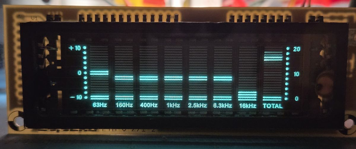
    The VFD is a different look though, in my opinion it has a bit more charm.

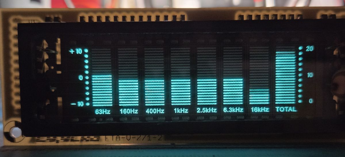
    Below is my retro fun with the VFD analyser:

    Turquoise-lit VFD display showing an audio spectrum analyzer with side level scales Turquoise-glowing VFD display with spectrum analyzer bars and frequency band labels
  • #100 21905423
    James596
    Level 29  
    Posts: 1817
    Help: 139
    Rate: 521
    tytka wrote:
    VFD it looks different though, in my opinion it has a bit more charm.


    There is no denying it. However, I think the pace and fluidity of the presented analyser mimics this well. :)
  • ADVERTISEMENT
  • #101 21905489
    efi222
    Level 21  
    Posts: 727
    Help: 12
    Rate: 1183
    More and more DIYers are sourcing a 3D printer. This project is a budget device that can be built by anyone with a printer and... an iron :) And as someone wrote here earlier, there's no space technology here. Admittedly, I once encountered a statement on Elektroda that 3D printing is not DIY.... I reply: if this person thinks that such an enclosure will be taken off the printer's table then good luck:)

    VFDs have their charm undeniably. However, there is often a sentimental feel reminiscent of a bygone era. Although these displays seem to be used in current hardware productions too.

    As for the movement of the bar in the spectrum, @398216 Usunięty presented the mathematical dependencies of this movement in some of his articles.
    I set it "by eye" :)

    VFD , TFT and then there is LED. I really like designs with LED. This optoelectronic element is very fast compared to the rather slow TFT. A different approach to animation.
    As an example, I attach a video of a full-size (436mm wide) spectrum on addressable SK6812 mini-E LEDs - for Denon equipment. Yes - I am a post geek :D
    The video is from a later stage of construction. Sorry for the background :)
    And in this case, without a 3D printer, no go. The pole displays need to be (manufactured).
    I don't know why the sound jitters a bit on Chrome PC. On android devices it is ok.


  • #102 21905543
    ArturAVS
    Moderator
    Posts: 26136
    Help: 2295
    Rate: 7745
    @efi222 Try making a "lamp" a'la VFD/Nixie on addressable diodes in some sort of test tube. There would probably be some interest. :D
    efi222 wrote:
    Yes - I'm a post geek

    :D I'll find a moment, then I'll get my old analyser up and running and record a video. Completely analogue with a VFD.
  • #103 21905664
    efi222
    Level 21  
    Posts: 727
    Help: 12
    Rate: 1183
    ArturAVS wrote:
    old analyser and record film. Completely analogue with VFD.

    This could be an interesting experience. I wonder if anyone would still undertake spectrum on analogue filters these days. Lots of work to do.

    And I'll come back to the 'lamps' again :)
  • #104 21905668
    ArturAVS
    Moderator
    Posts: 26136
    Help: 2295
    Rate: 7745
    I have had this analyser for over 20 years. Mainly because of the equalizer, the analyser itself is a secondary function. The sentiment remains, and it sits waiting to be rechambered. A Sony MD/CD, it blended nicely with the other components of the set. The only thing I did after getting it was to remove the plastic filters from the display. Last year, just before BN Christmas, I was visited by a friend from whom I had 'acquired' it. -And you still have it! -How much do you want for it! When I get it up and running, (I don't know if it works, it's been a long time since it was switched on) I'll make a video of it working especially for you @efi222.
  • #105 21905673
    efi222
    Level 21  
    Posts: 727
    Help: 12
    Rate: 1183
    ArturAVS wrote:
    specially for you @efi222 , I will record a video of his work

    Super thanks :)
  • ADVERTISEMENT
  • #106 21905679
    ArturAVS
    Moderator
    Posts: 26136
    Help: 2295
    Rate: 7745
    You will have a comparison of how the "bars" for the VFD work. The Audio track, is completely analogue, bandpass filters on LM324, + some "digital" to control the display itself (multiplexing etc).
    I haven't modified anything in it (apart from these filters). On the electronic side, factory.
  • #107 21905781
    robgold
    Level 23  
    Posts: 722
    Help: 10
    Rate: 289
    tytka wrote:
    Other than that, I have not had the best experiences with prints. Often after some time, printed components working under a certain load most simply break, delaminate.
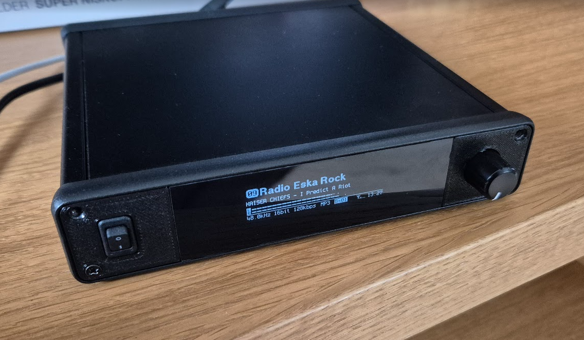
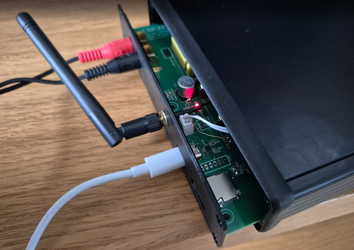
    I don't have this experience but with me the minimum is PETG. PLA material has precisely the problems you write about.
    Radio Evo has a housing just printed from PETG and nothing has happened to it to this day and it's been well over a year. I have "caps" on my fence made of PETG and ABS for comparison and those made of PETG are still intact, yet it's frost and sun.


    A rather cool combination is the alu profile enclosure plus its own printed panel front. This combines a certain amount of elegance and at the same time the ease with which the holes for the display or buttons can be made


    DIY micro tower (desktop version) DIY micro tower (desktop version)

    Added after 2 [minutes]:

    >>21905664 Not that much. I have somewhere an old kit for assembling just such an analyser from the TODAKS company. A few amplifiers at a time. Simple design, I will find it to run :)
  • #108 21905784
    tytka
    Level 23  
    Posts: 753
    Help: 8
    Rate: 1831
    efi222 wrote:
    And in this case, without a 3D printer, no go. You have to (manufacture) the pole displays.

    Not a move? Are they really?
    Sorry, but as far as I'm concerned, that's a 3D printer user's opinion though.
    With a bit of ingenuity it is possible to do something similar without printouts.
    I don't want to negate your work here at all, on the contrary; I am full of admiration for what you do. Because what you do, you do very well indeed. However, with this opinion, I simply cannot agree.
    If you had stated here that it is much easier, then yes, then I would agree with such an opinion.

    ArturAVS wrote:
    "posts" for VFD. The Audio track, is completely analogue, bandpass filters on the LM324, + a bit of "digital" to control the display itself (multiplexing etc).
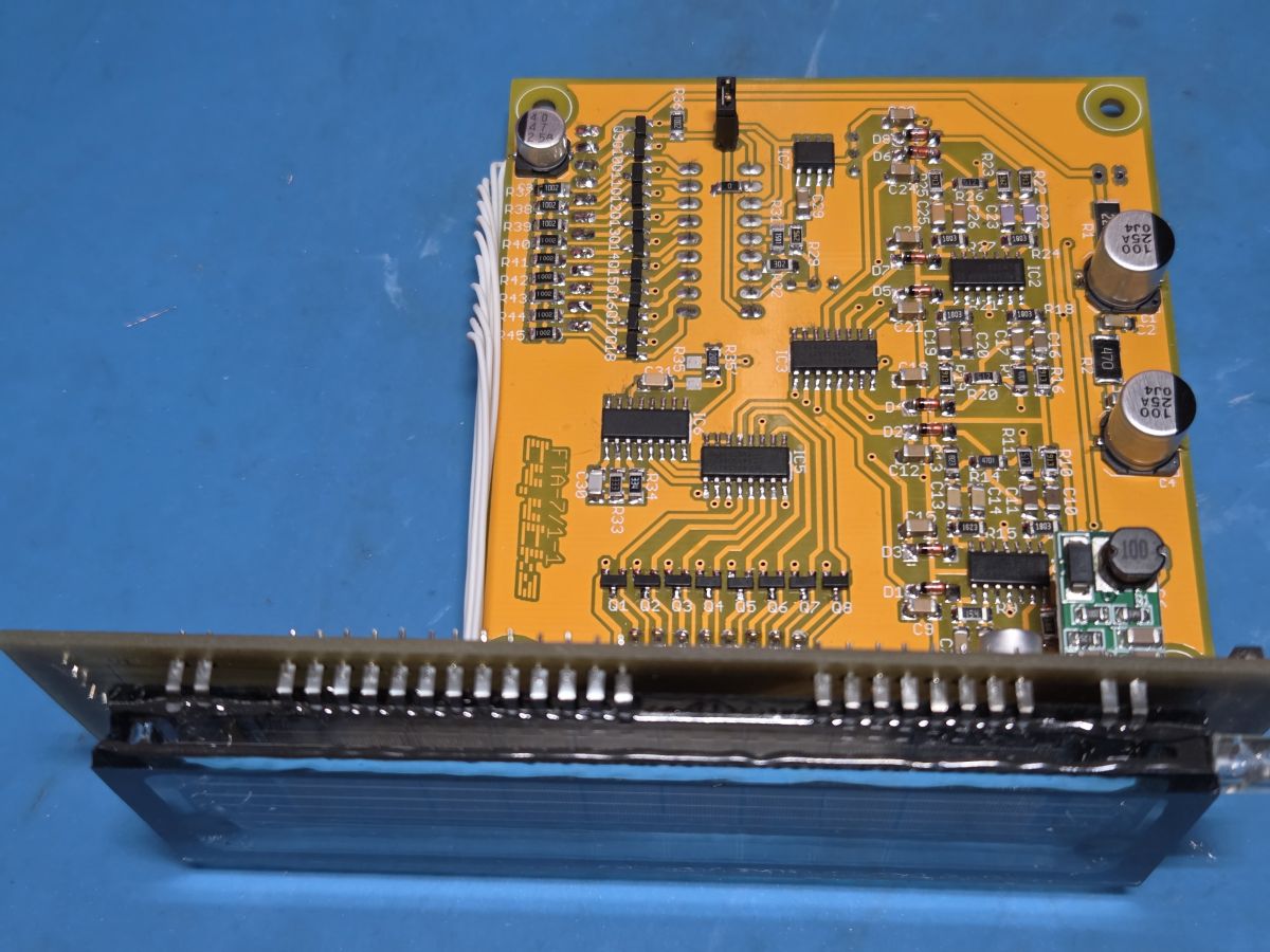

    Hmm... :) :)
    DIY micro tower (desktop version)


    robgold wrote:
    A rather cool combination is the alu profile enclosure plus its own printed panel front. It is such a combination of a certain amount of elegance and at the same time the ease of making holes for the display or buttons
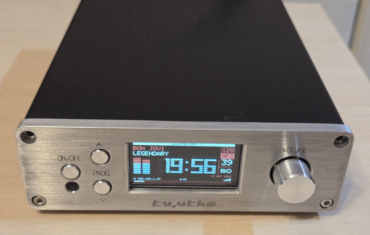

    It worked out quite nicely for you,
    I, however, would still stay with the combination of aluminium and aluminium. It is more difficult to make, but it is doable.
    Below is a working photo of my design.
    Brushed aluminum device front with 19:56 display, three buttons, and a volume knob

    And let me assure you that my experience with the prints is unfortunately not off the mark.
  • #109 21905827
    robgold
    Level 23  
    Posts: 722
    Help: 10
    Rate: 289
    >>21905784 I'm not saying that alu is bad, because I did exactly the same as you, well maybe only the front would not have gone through with me. It had to be anodised on the spot or it had to be milled in such a way as to preserve the original. But time, playing around with the G-code, then setting up the milling machine. I guess as I got older I realised that you can live with print quality. I used to be very annoyed by layer marks. Nowadays, proper textured plates mask a lot and printers with closed heated chambers allow a lot more.

    I need to dust off that CNC and maybe do at least one Evo version in full Alu. You have encouraged me ;)
    Unquestionably being made in 100% aluminium gives a greater sense of prestige to the machine and quality. There is not even anything to discuss here.

    One more option that the 3D printer has given is the ability to print all the technical mounts in these aluminium housings. You make yourself a mount for an encoder or for a display out of PETG and with a good glue you attach it to the alu front. I think most professional equipment just combines such techniques. Only the simple front is made of brushed aluminium and behind it is a plastic support.

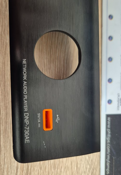
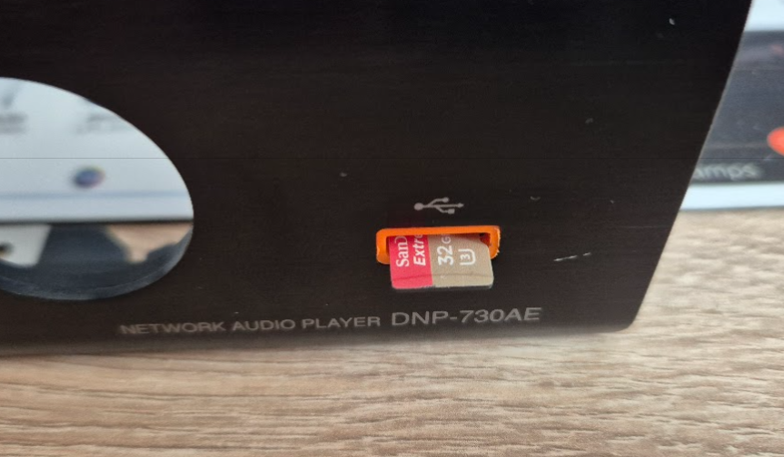
    I have, for example: such a Denon DNP to convert into an Evo. The printer allows you to make the entire SD card slot in a few minutes. The colour is specially designed for prototypes so that any flaws or shortcomings can be seen.

    DIY micro tower (desktop version) DIY micro tower (desktop version) DIY micro tower (desktop version)


    The OLED display has also been whisked away by someone and since it sits there at 3.55 inches and not 3.12 the printer is invaluable for making a proper conversion.
    DIY micro tower (desktop version)

    I'm throwing this in as inspiration, combining multiple processing techniques and materials always gives interesting results.
  • #110 21905850
    efi222
    Level 21  
    Posts: 727
    Help: 12
    Rate: 1183
    tytka wrote:
    Any move? Are you sure?
    Sorry, but as far as I'm concerned, that's a 3D printer user's opinion though.
    With a bit of ingenuity it is possible to do something similar without printouts.

    Well perhaps I have expressed myself badly. I had already thought about building such a spectrum before I acquired the printer. I am not afraid of various manual works. But unfortunately I had no idea how to make something like this homemade.


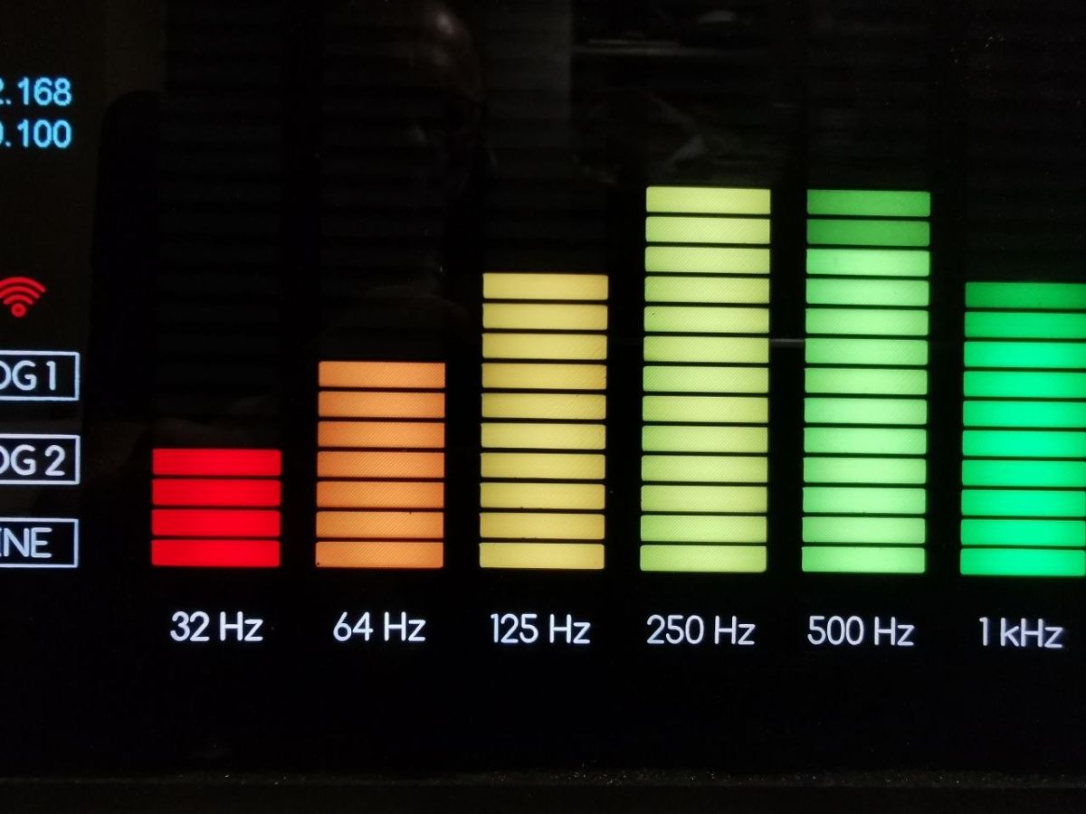
    Or else, to achieve this LED masking effect. Pixel size 2.6x14mm
    Colorful graphic equalizer bars labeled 32 Hz to 1 kHz on a black display

    The printer got the job done. This is the effect of the printed LED mask. A fragment of the spectrum presented it above.


    And regarding the PLA prints. I haven't noticed anything happening to them. I also have sensors from a weather station from four years outdoors in cold and hot weather. One even hangs in a printed openwork basket. Everything looks like it did in the beginning. Fact, with black prints you have to be careful in the sun. There are also a lot of different printed enclosures at home. And if there are greater requirements there is always PET-G.
    PLA is unlikely to break, it will only deform if some force acts on it for a long time. Well, unless someone wants to destroy something by force :)

    tytka wrote:
    I, however, will still stay with the combination of aluminium and aluminium. It is more difficult to make, but it is doable.
    Below is a working photo of my design.

    Beautiful work. In my opinion it would be even more beautiful with a larger window for the display. A larger margin around the display.

    robgold wrote:
    A rather cool combination is the alu profile type enclosure plus its own printed panel front. It is such a combination of a certain amount of elegance and at the same time the ease of making holes for the display or buttons
    Very cool form.

    Added at 11 [hours] 9 [minutes]:

    ArturAVS wrote:
    @efi222 Try making a "lamp" a'la VFD/Nixie on addressable diodes in some kind of test tube.
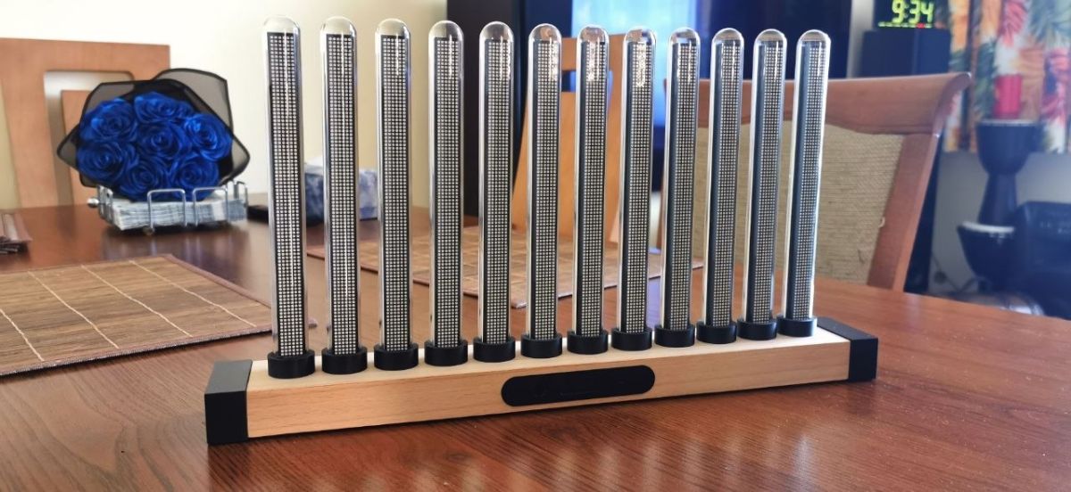

    As far as the spectrum is concerned, this is the kind of test I was doing (for a colleague):
    DIY micro tower (desktop version)

    Finishing the base with natural veneer:
    DIY micro tower (desktop version)

    And in movement:


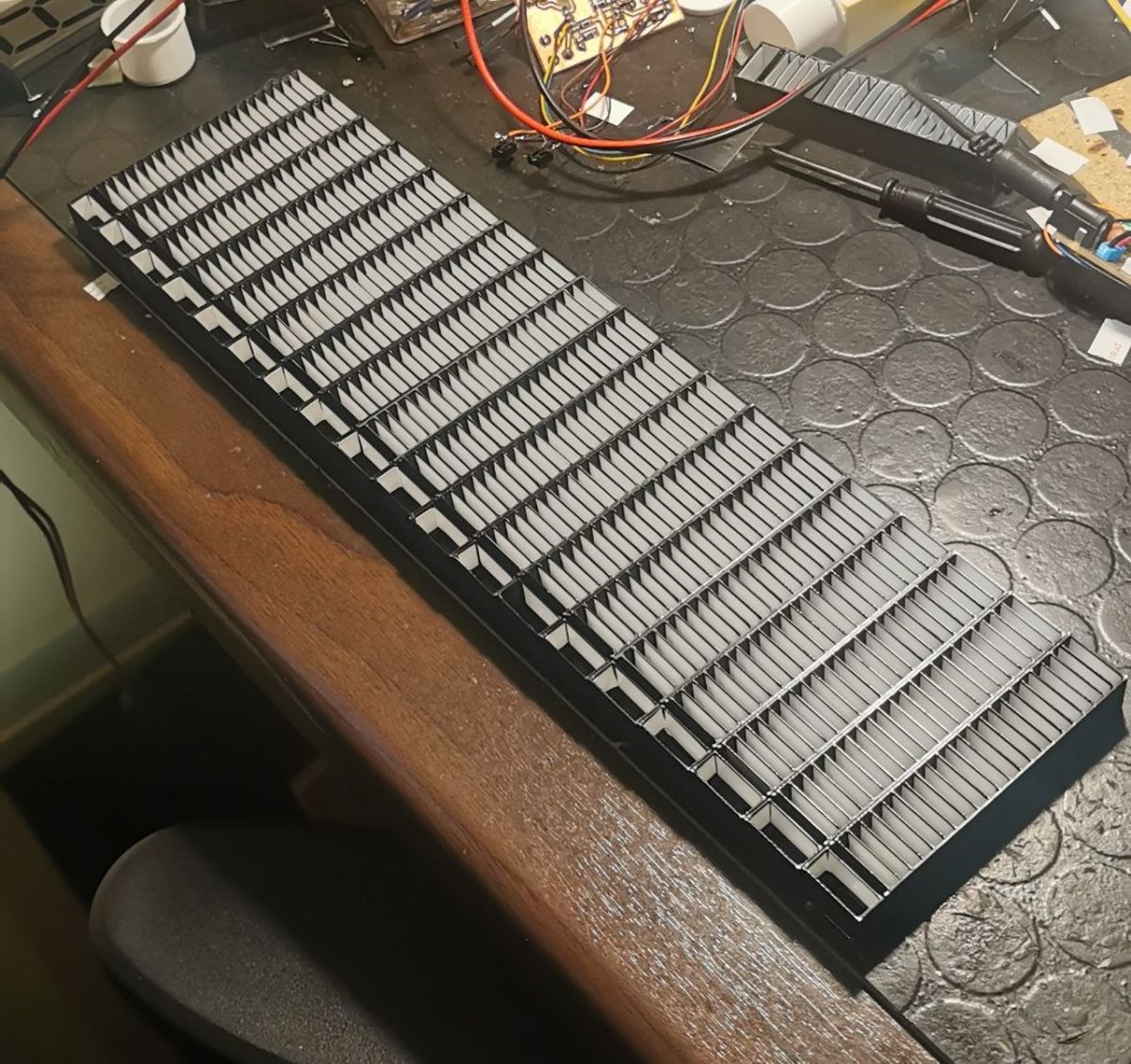
    Still, I found a photo of the shut-offs for the LED Spectrum on LED. The compartments had to be lined with white veneer to diffuse the light. Anyone have any idea how to do something like this without 3D printing technology?
    DIY micro tower (desktop version)
  • #111 21906023
    ArturAVS
    Moderator
    Posts: 26136
    Help: 2295
    Rate: 7745
    Simply beautiful.
  • #112 21906063
    robgold
    Level 23  
    Posts: 722
    Help: 10
    Rate: 289
    >>21905850 All in all, a lot of work with this decking. Haven't you thought about printing it white and only the fronts possibly painted black or printing the overlays black?
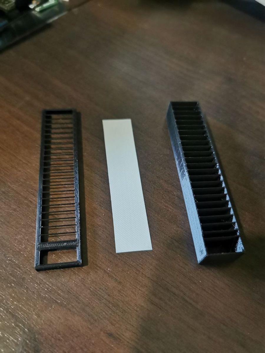
    And how to do it without 3D printing...matchboxes. Such a first thought :D
    Probably some of us have such parts drawers ;)
  • #113 21906104
    efi222
    Level 21  
    Posts: 727
    Help: 12
    Rate: 1183
    robgold wrote:
    Have you not thought to print it white and only the fronts possibly painted black
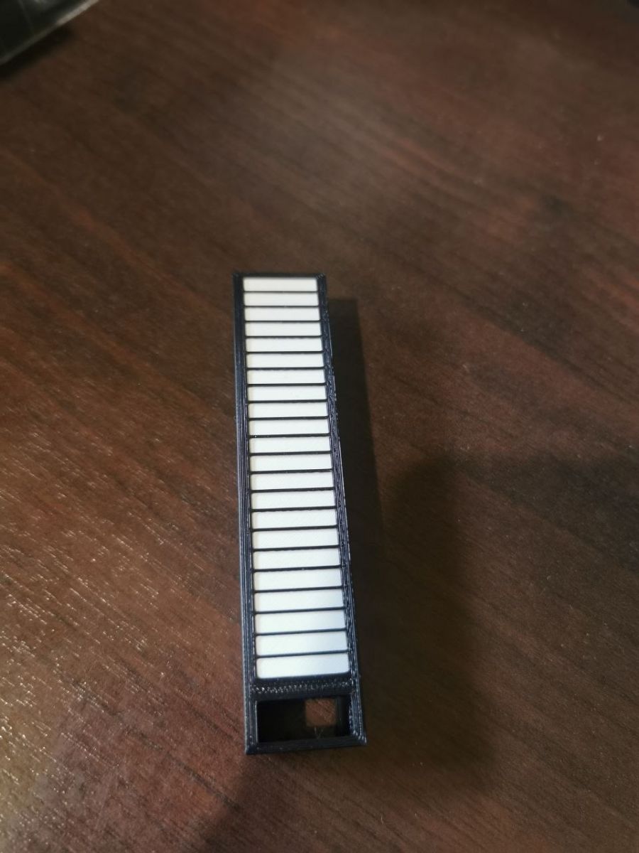
    The fenders have to be made of black filament. White lets light into the adjacent chamber.

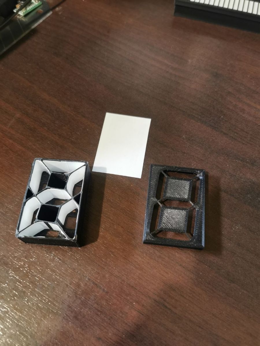
    Pictorial images of one post.
    DIY micro tower (desktop version)
    DIY micro tower (desktop version)

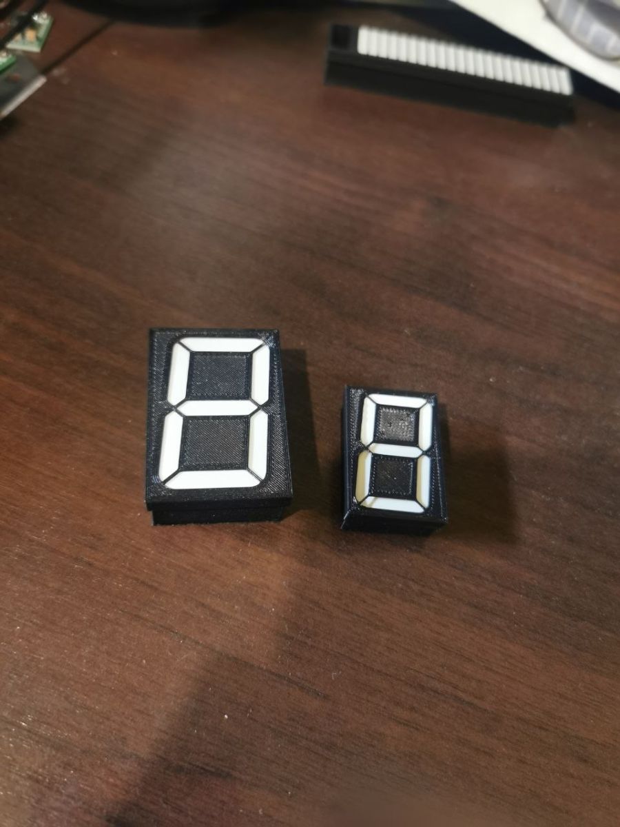
    7 segment digits can also be made
    DIY micro tower (desktop version)
    Two black seven-segment digit modules with white segments on a wooden tabletop

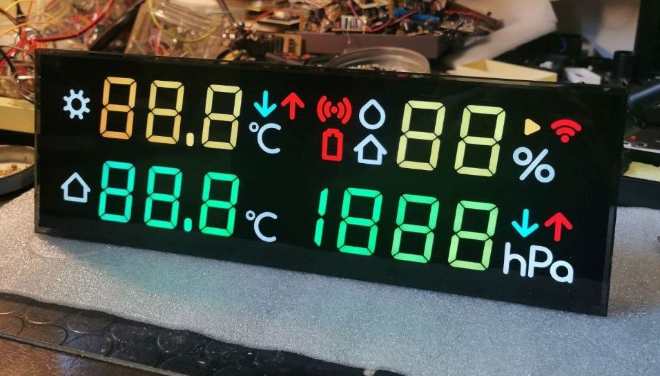
    Weather station made of such figures. Demo mode.
    LED weather-station display with multicolor 7-segment digits and icons on a cluttered electronics workbench

    Illuminated lettering is etched thin laminate.
    Strip with black framed labels and white frequency text (e.g., 16 kHz, 500 Hz, 32 Hz)


    robgold wrote:
    And how to do it without 3D printing...a matchbox. That was my first thought

    Well not that size :D The post chamber is 3x17mm .
  • #114 21906225
    tytka
    Level 23  
    Posts: 753
    Help: 8
    Rate: 1831
    robgold wrote:
    Only the simple front is made of brushed aluminium and behind it is a plastic support.

    This is often the case, although sometimes the internal support front plate is metal.
    In diy constructions, it can be made from laminate. With this, you can also make the necessary brackets and even mounts for the display. I have personally practised this.

    efi222 wrote:
    Have anyone an idea how to make something like this without 3D printing technology?

    I used to make something similar, but not quite as sizeable. And I made it out of thin laminate and thin copper sheet. At the end it was spray-painted. Unfortunately I don't have pictures of this construction of mine.

    efi222 wrote:
    As for the PLA printouts. I haven't noticed anything happening to them.
    I have no idea what the parts I had problems with were printed from. They were components of some equipment I was dealing with and clearly they were printed. They were used internally, so the factor of adverse weather conditions falls away. But as I mentioned they were subjected to some mechanical stress and this was most likely the cause of their delamination.
  • #115 21906445
    AP200
    Level 13  
    Posts: 42
    Rate: 2
    A very cool idea and even better execution.
  • #116 21906449
    robgold
    Level 23  
    Posts: 722
    Help: 10
    Rate: 289
    >>21906225 If the print is to be subjected to loads then it must be printed in the correct way otherwise it will start to crack at the joining of the layers as this is the weakest point. You need to print at an angle and rotate the object accordingly.
  • #117 21906459
    efi222
    Level 21  
    Posts: 727
    Help: 12
    Rate: 1183
    >>21906449
    Too low a temperature at the nozzle will result in poor thread bonding and therefore the final print will be weaker.
  • #118 21906504
    tytka
    Level 23  
    Posts: 753
    Help: 8
    Rate: 1831
    >>21906459 >>21906449
    I cannot exclude the possibility that someone who printed these elements did not make some mistakes.

    And regarding applying descriptions to the front panel.
    Below is my attempt today.
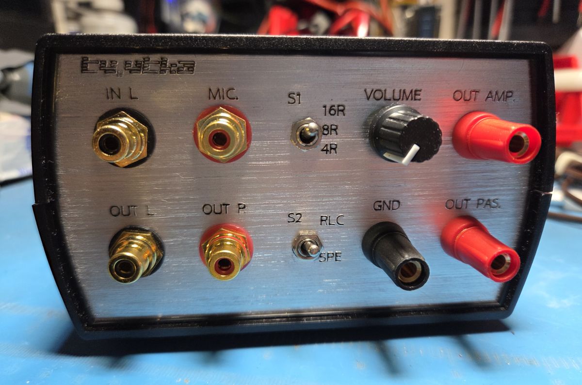
    A working device, so it didn't have to look perfect. Universal housing made of ABS. Spray-painted front and laser-burned descriptions. A very soft and fusible material for such a method, but I think it came out tolerably well. Judge for yourself.

    DIY micro tower (desktop version)
  • #119 21906603
    Olkus
    Level 32  
    Posts: 3920
    Help: 132
    Rate: 917
    In my opinion - very good :)

    Regards,
    A.
  • #120 21906904
    robgold
    Level 23  
    Posts: 722
    Help: 10
    Rate: 289
    >>21906504 Did you give primer to the plastic under the paint proper? You can see just what you wrote, that the material is very fusible and made mountains from the laser but for a working device it is very decent!

    I've recently become interested in UV printers that can print complete descriptions of fronts. For example: eufyMake UV E1 ...only the price :/
ADVERTISEMENT