logo elektroda
logo elektroda
X
logo elektroda

TL;DR

  • A DIY micro tower combines a radio, spectrum visualizer, and amplifier in two compact desktop enclosures.
  • The radio uses ESP32S3, a 2.8-inch IPS display, MPR121 touch sensing behind 4 mm tinted glass, and encoder-based station browsing.
  • The units measure 200x61x130 mm for the radio and 200x40x130 mm for the spectrum and amplifier sections.
  • The spectrum runs on an ESP32 using both cores, refreshing two 1.9-inch IPS displays at 37 to 41 FPS.
  • The amplifier is not hi-fi, uses a TPA3110 module and AVT kit 2132 tone control, and the station list is stored rigidly in firmware.
Generated by the language model.
ADVERTISEMENT
Treść została przetłumaczona polish » english Zobacz oryginalną wersję tematu
  • #61 21901753
    DJCheester
    Level 28  
    Posts: 2071
    Help: 75
    Rate: 951
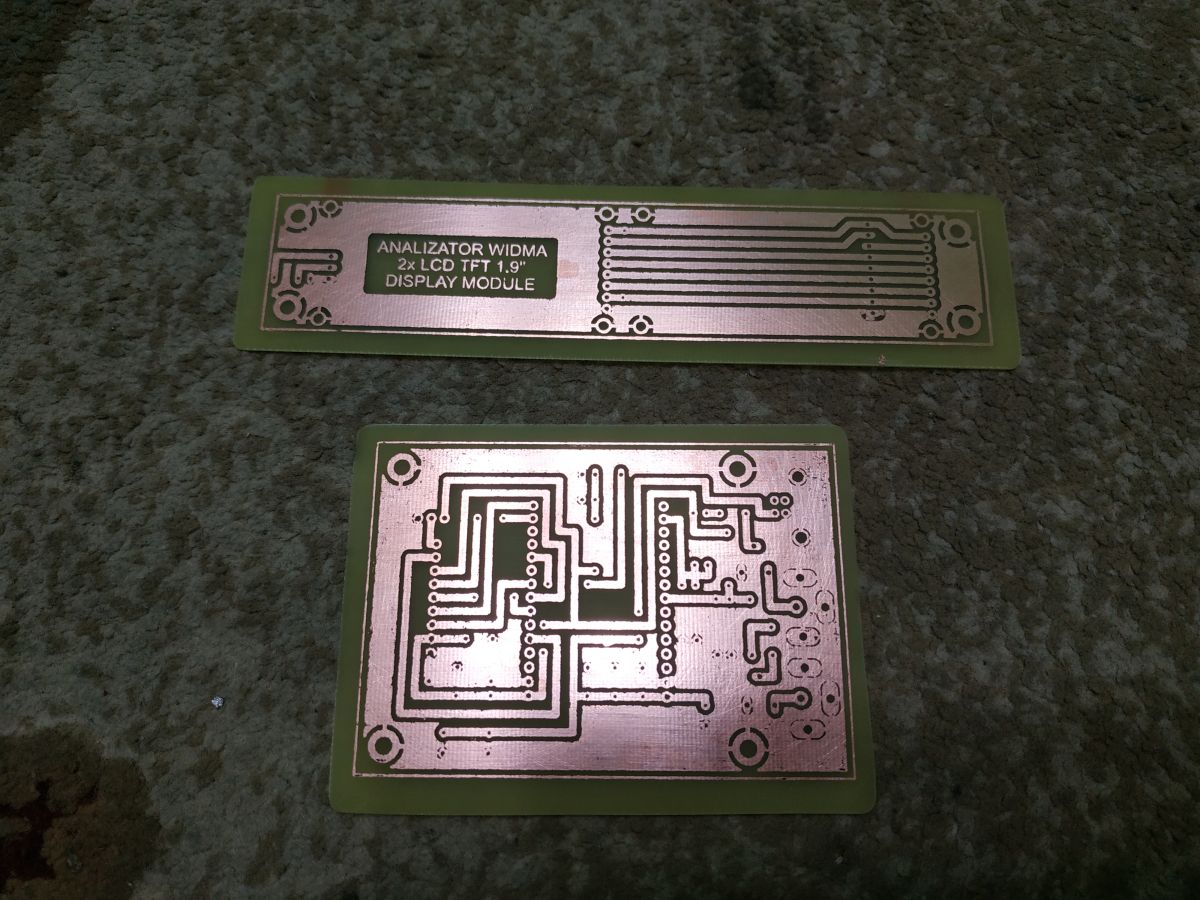
    You can always make a PCB V2 that conforms to the schematic 100%.

    In this version, an IR remote control with TSOP31238 is designed, because the idea was to use the IR to change the otwy. The connector for the encoder can be added as much as possible.

    Greetings ...
  • ADVERTISEMENT
  • #62 21901754
    efi222
    Level 21  
    Posts: 727
    Help: 12
    Rate: 1183
    It used to be that everything was on isostats and people were happy :D
  • ADVERTISEMENT
  • #63 21901755
    DJCheester
    Level 28  
    Posts: 2071
    Help: 75
    Rate: 951
    Efi222 so it would be good to specify the hardware (as it was for the radio (Robgold's colleague) to make a universal PCB - you can design IR but not necessarily use it in software (for the time being).

    Greetings....

    Added after 1 [minute]:

    efi222 wrote:
    It used to be all on isostats and people were happy :D


    Probably especially from the telegraph 😀

    But times are rightly past.

    Nowadays without the net you can't move 😀

    Greetings ...
  • #64 21901762
    efi222
    Level 21  
    Posts: 727
    Help: 12
    Rate: 1183
    There are quite a few free pins in the ESP32, in the spectrum circuit. I will test some free one to be sure and add it to the schematic.
  • #65 21901765
    DJCheester
    Level 28  
    Posts: 2071
    Help: 75
    Rate: 951
    O this would then be everything + a UART connector for using this as an attachment for mate ejcon's radio mods in the internet radio topic.

    Regards...
  • #66 21901773
    efi222
    Level 21  
    Posts: 727
    Help: 12
    Rate: 1183
    I'm thinking of a slightly different IR control.
    IR in the amplifier only (there is an Atmega with free rework). And from it make a UART bus with commands to the other modules. The distances are not great, so there is a chance to make it work.
  • #67 21901774
    DJCheester
    Level 28  
    Posts: 2071
    Help: 75
    Rate: 951
    But that would involve a cable connecting all the blocks, like Technics towers used to do. Isn't it better to give receivers in each pad and assign different buttons to each pad.

    Simple and without unnecessary connections except for power and Chinch.

    Greetings....
  • ADVERTISEMENT
  • #68 21901781
    efi222
    Level 21  
    Posts: 727
    Help: 12
    Rate: 1183
    >>21901774
    Time will tell. As of today, it is "a song of the future".... :)
  • #69 21901782
    DJCheester
    Level 28  
    Posts: 2071
    Help: 75
    Rate: 951
    But design at some pin already 😀

    Greetings....
  • #70 21901886
    tytka
    Level 23  
    Posts: 753
    Help: 8
    Rate: 1831
    efi222 wrote:
    A pity because the printer makes the job easier. (...)
    Of course, plastic prints are not suitable for all structures and will not replace more durable steel or aluminium components and housings. Well, but something for something.

    For those who don't print. Photos of the raw housing for the radio with sides. Now you have to turn on manual beautification mode


    Well that's what makes it easier, but of the above mentioned I don't really like printing and still don't own a 3D printer.
    I prefer to tinker in aluminium or other metal, or possibly wood or plastic.

    By the way, as I've only just now paid attention.
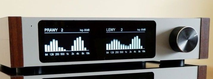
    It would probably be more appropriate for the left to be on the left and the right to be on the right.

    Audio device panel with spectrum display labeled “PRAWY” and “LEWY” and a large knob
  • #71 21901894
    efi222
    Level 21  
    Posts: 727
    Help: 12
    Rate: 1183
    tytka wrote:
    And by the way, as I've only just now paid attention.
    It would probably be more appropriate for the left to be on the left and the right to be on the right.

    Of course :D . Already reported by someone commenting. I need to swap the CS wires of the displays. I'm not going to take a new photo anymore. It's poor at photographing glass panels, LEDs and luminescent elements and it takes some time.
  • #72 21901997
    bobojad
    Level 14  
    Posts: 112
    Rate: 13
    >>21899218 Hi, great work. I wanted to ask in turn how exactly those buttons with the white AUX/RADIO/BT lettering were created. Is this a two-colour print or did you somehow fill or tape the PLA board? I'm looking for a method to make illuminated lettering that is resistant to abrasion, like the buttons on car radios.
  • ADVERTISEMENT
  • #73 21902080
    efi222
    Level 21  
    Posts: 727
    Help: 12
    Rate: 1183
    >>21901997
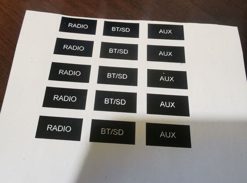
    The buttons are a printout. I print the button lettering on a laser printer, on glossy adhesive paper (matte can probably work too).
    Before gluing, I heat the printout with hot air until the toner starts to shine. I wonder if this is necessary. I use the heating procedure for information stickers, e.g. socket descriptions on the back of the case. The toner is then more resistant to abrasion.
    DIY micro tower (desktop version)

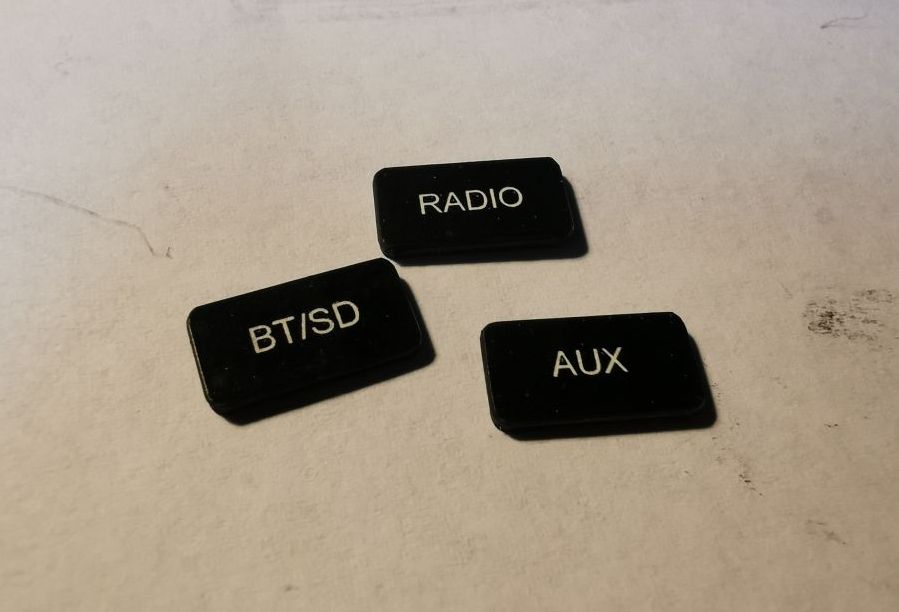
    I apply the sticker to the button. It is a little larger. I trim off the excess with scissors. Then I sand the edge with a flat fine needlepoint. After this procedure, the white paper of the sticker will appear on the edge because the toner will come off by the way. I retouch this with a black marker. Finally, a matt clear varnish.
    DIY micro tower (desktop version)
    In the photo a considerable enlargement. Inscription height 2mm.

    I thought about illuminated buttons, but nothing sensible came to mind :)
  • #74 21902090
    ArturAVS
    Moderator
    Posts: 26136
    Help: 2295
    Rate: 7745
    @efi222 I'm trying it on with Mechanic UV varnish. I already have a few colours in stock. (Black, green, white). Initial trials look encouraging... Even a description of the front panel can be done.
  • #75 21902094
    sq3evp
    Level 39  
    Posts: 6445
    Help: 212
    Rate: 849
    Beautiful - there has always been a problem with front panels. I still have that simple power supply, I'll make a panel for it now. It's on 13.8V, but I'm planning to add a potentiometer with regulation around 12V to test different ones.
  • #76 21902105
    efi222
    Level 21  
    Posts: 727
    Help: 12
    Rate: 1183
    ArturAVS wrote:
    It is even possible to make a description of the front panel.

    And this is interesting..., because front panel lettering is also a bad dream....
  • #77 21902116
    ArturAVS
    Moderator
    Posts: 26136
    Help: 2295
    Rate: 7745
    efi222 wrote:
    the captions on the front are also a bad dream...

    If it weren't for the fact that my printer has "gone rogue", i.e. under Linux it doesn't "work", I'd show samples. Roughly, on tinted Plexi, and applied with a soft rubber roller varnish, after UV exposure through film (similar to PCB photochemistry); https://www.elektroda.pl/rtvforum/topic3937477.html#20307992 Looks like screen printing.
  • #78 21902318
    wieh76
    Level 12  
    Posts: 57
    Rate: 23
    DJCheester don't you happen to have gerbers for these boards? I already have the radio and would love to add this analyser to the set🙂 .
  • #80 21903039
    kahvm
    Level 10  
    Posts: 8
    Rate: 1
    Honestly? It looks great!
    A perfect combination of modernity, style and ... and illusion (because I still see a tarnished etched metal panel, wood sides, not 3d printing and ready-made digital modules) ;)
    On the one hand - nothing special, some ready-made layouts, printing, veneers.
    All replicable (all the more chapeau bas for the details) without any cosmic technology or cost.
    It is also possible to realise a balanced functionality (even partially) or move to a different aesthetic on the cheap.
    On the other - sensible choice of 'equipment' and materials, perfect details, successful cinematography (if it wasn't for the video, I would have thought it was a 'humanised' render).
    And that dark glass in the "metal" - neatly offsets the shortcomings of these LCDs (greying blacks, bezels, etc.).
    For the full so-called experience, a photo "from the back" is missing.
    I know that it can be connected in a working way, i.e. practically.
    But you might as well make these connections in the style of the rest - i.e. thoughtful, evocative and pleasing to the eye.
    Even if they were to pretend to be audiophile analogue.
    Looking at the details on the front or the author's other design (I would call it a "contemporary interpretation of nixie tubes") - I am convinced that this stage could be an excellent complement to this design.
    And, if you can ask for more photo-video, video not only static, but also such a front-to-back or even 360° presentation :)
  • #81 21903052
    efi222
    Level 21  
    Posts: 727
    Help: 12
    Rate: 1183
    >>21903039
    I'll say this: I don't even know what to write back.
    I didn't expect such a review. Very interesting description. Thank you for your words of appreciation. :)
    I will try to prepare more material and publish :)
  • #82 21903074
    kahvm
    Level 10  
    Posts: 8
    Rate: 1
    >>21903052
    A review would be if I had used or even seen it live.
    And as if I were someone known in the environment, and I am just a passive observer ;)
    Here it is - just an opinion and the proverbial pat on the back, because more, via the internet, is not possible.
    If you upload anything else, I'd be happy to review the material.
    And it's nice to hear that a few of my words provide some value and motivation for you. Thanks for your reply :)
  • #83 21903129
    erni750906
    Level 8  
    Posts: 10
    I like this radio and I think I will make one .Just one question about the spectrum because I see you made it on esp32 but on wifi board only and if I have esp32 board but the extended one will the spectrum also go on this board and do I have to make the preamp according to your schematic or can I put some ready made one and the question is about the radio as for esp32 . And I have a request if it would be possible to get the code to print the housing , radio , spectrum and amplifier thank you very much in advance.
  • #84 21903157
    efi222
    Level 21  
    Posts: 727
    Help: 12
    Rate: 1183
    >>21903129
    You can use any modules you like. Developers or development boards. Development boards often have differently labelled I/O pins. My schematics show the original GPIO port designations.
    You need to look up how the port names are mapped on the development boards you acquire.

    Spectrum: ESP32-Wroom-32D or older ESP32 Wroom-32.
    Radio: ESP32 S3 1NR16R8
    For stl files get back to me on priv.

    The schematic of the amplifier is not in this topic. There is only its touch switch and the power supply for the other modules.
    You can make the amplifier as you like.
  • #85 21903176
    Karol966
    Level 31  
    Posts: 2037
    Help: 83
    Rate: 645
    A beautiful realisation indeed. It's been a long time since we've seen something of a similar level of workmanship here. It looks like a product from a hi-fi shop.
  • #86 21903298
    Olkus
    Level 32  
    Posts: 3920
    Help: 132
    Rate: 917
    efi222 wrote:
    It is possible as long as the sound source sends this information.


    I was thinking of building a USB DAC and/or BT module inside. So in theory it should probably be possible. But it's just an afterthought, I don't have much experience in the subject, so I don't know if I'd be able to do something like that, because without a CPU it's unlikely to work :)

    Regards,
    A.
  • #87 21903358
    cranky
    Level 30  
    Posts: 2042
    Help: 68
    Rate: 376
    Beautiful. Simply beautiful. The only thing I would miss would be the station selection/approval menu by pressing the knob (unless turning the knob without entering the menu changes the station).
    What is the cost of such a set for friends?
  • #88 21903418
    efi222
    Level 21  
    Posts: 727
    Help: 12
    Rate: 1183
    cranky wrote:
    confirmation of the station by pressing the knob

    I deliberately dispensed with mechanical buttons because of the low weight of the turret The whole thing weighs 1.3 kg. With such a weight, pressing the encoder moves the gear. You would have to hold it. This is why the operation is tactile. The video at the end of the article shows, among other things, the operation of the radio. It is operated very comfortably in my opinion :)

    Added after 5 [minutes]:

    cranky wrote:
    What is the cost of such a set for friends?

    I'll admit that I haven't even counted the parts yet. But they are not cosmic costs.
  • #89 21904027
    tytka
    Level 23  
    Posts: 753
    Help: 8
    Rate: 1831
    efi222 wrote:
    because the lettering on the front is also a bad dream...


    The lettering on the front can be engraved with either a cutter or a laser.
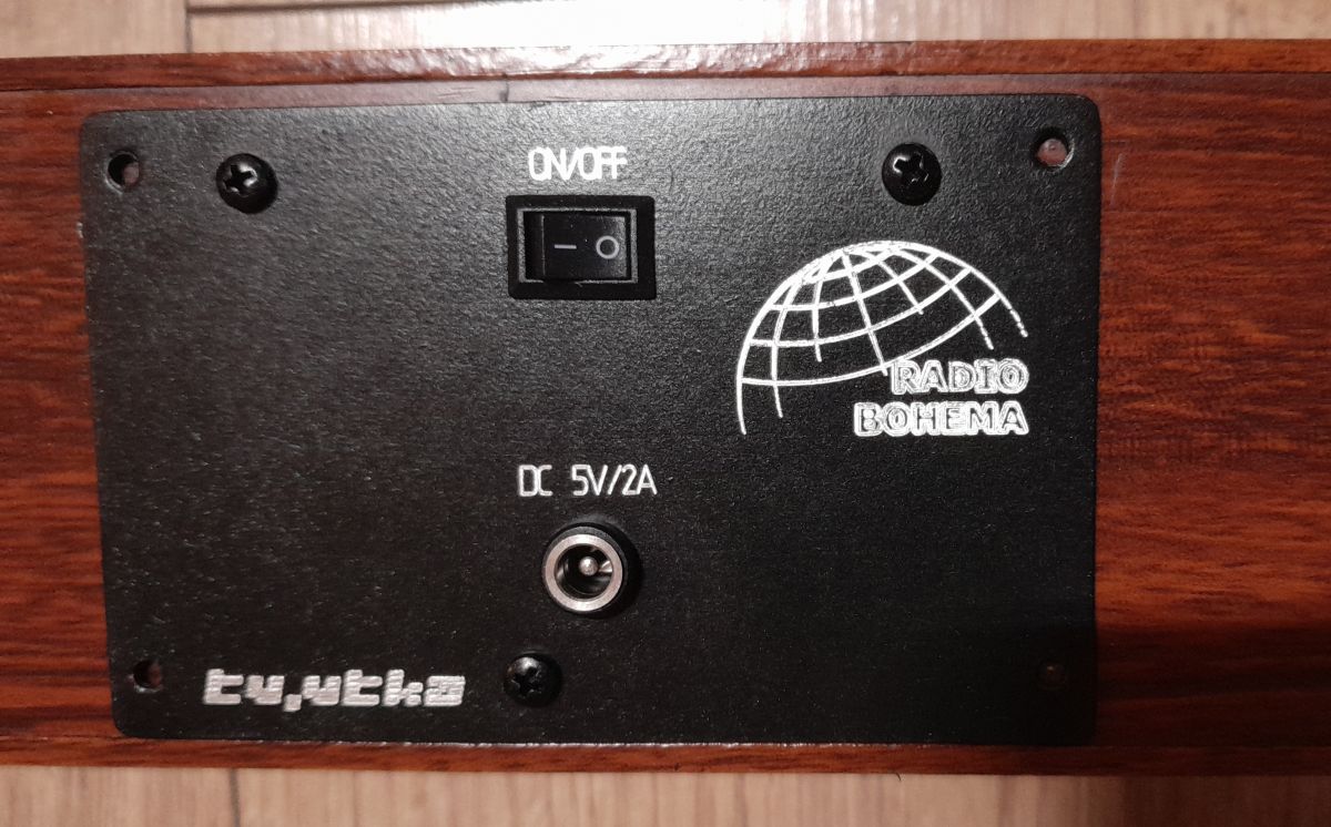
    Here the cutter in aluminium completed with paint:

    DIY micro tower (desktop version)

    Here, milling cutter on aluminium painted black:

    DIY micro tower (desktop version)

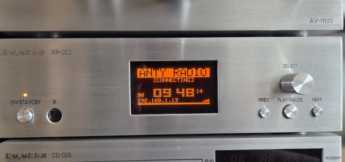
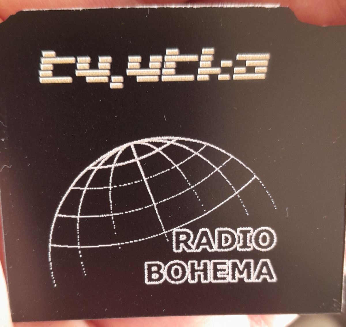
    And here an attempt at laser engraving on engraving laminate:


    DIY micro tower (desktop version)
  • #90 21904070
    efi222
    Level 21  
    Posts: 727
    Help: 12
    Rate: 1183
    tytka wrote:
    The inscriptions on the front can be engraved with both a cutter and a laser.

    Unfortunately, I own neither. This looks very good. The cutter is more for hard surfaces. I wonder if such a laser would pass the test on, for example, self-adhesive foil such as is on the front of the turret from this topic. There is black plastic underneath it. It seems that it should. The thickness of such a foil is about 0.1 - 0.15 mm.
ADVERTISEMENT