logo elektroda
logo elektroda
X
logo elektroda

TL;DR

  • A DIY micro tower combines a radio, spectrum visualizer, and amplifier in two compact desktop enclosures.
  • The radio uses ESP32S3, a 2.8-inch IPS display, MPR121 touch sensing behind 4 mm tinted glass, and encoder-based station browsing.
  • The units measure 200x61x130 mm for the radio and 200x40x130 mm for the spectrum and amplifier sections.
  • The spectrum runs on an ESP32 using both cores, refreshing two 1.9-inch IPS displays at 37 to 41 FPS.
  • The amplifier is not hi-fi, uses a TPA3110 module and AVT kit 2132 tone control, and the station list is stored rigidly in firmware.
Generated by the language model.
ADVERTISEMENT
Treść została przetłumaczona polish » english Zobacz oryginalną wersję tematu
  • #31 21900163
    DJCheester
    Level 28  
    Posts: 2071
    Help: 75
    Rate: 951
    If you value linearity, use a potentiometer, but potentiometers can be a pain. Noise crackles after many years, if it is an ALPS type, the advantage is that the knob turns by itself.

    I think I prefer digital, but this is my personal opinion.

    Greetings.....
  • ADVERTISEMENT
  • #32 21900166
    ArturAVS
    Moderator
    Posts: 26136
    Help: 2295
    Rate: 7745
    @efi222 I didn't expect such perfect workmanship in terms of the case. It is superb! Personally, I would have preferred a "mechanised" potentiometer in the amplifier, this is of course a matter of taste, but there is a second bottom line. In the event of WiFi 'failing', we have the option of controlling the volume manually (mechanically). Relying only on WiFi, in my opinion, is a serious mistake. I had the opportunity to convince myself of this.

    DJCheester wrote:
    plus that the knob turns itself

    But the visual effect, cool.
  • ADVERTISEMENT
  • #33 21900192
    robgold
    Level 23  
    Posts: 722
    Help: 10
    Rate: 289
    >>21900096 The library for RDA has a bug and you have to manually enable the LNA in the receiver. And you make the remote control so that each device learns but different buttons.
  • #34 21900209
    ElectroTom
    Level 25  
    Posts: 755
    Help: 43
    Rate: 203
    A gem on Elektroda. Thank you.
  • #35 21900390
    efi222
    Level 21  
    Posts: 727
    Help: 12
    Rate: 1183
    Specialist needed for "VU metres"
    I am combining something here as a motif for the spectrum, (on request) but somehow these clues "walk" strangely for me Or by moving posts I have messed up something in my head :D . Perhaps someone can guide me?


  • #36 21900477
    DJCheester
    Level 28  
    Posts: 2071
    Help: 75
    Rate: 951
    That's the kind of indicator I missed here 😀

    Greetings....
  • #37 21900613
    elukam
    Level 18  
    Posts: 400
    Help: 8
    Rate: 177
    efi222 wrote:
    FM is, in my opinion, slowly going into the background. You can play around with the receiver, but this is more for fun. A colleague is tiring such a receiver (RDA5807M) and is struggling with interference in the audio path. It interferes with the TFT display. He has combined with screens and other wonders and it doesn't help much.

    Because the colleague doesn't know. TFT screens, inverters and any other choppy circuitry are part of today's precision sensitive measurement equipment and somehow there is no problem. FM tracks with classic sperheterodyne, at least 10x more sensitive than these "digital" receivers also had interfering blocks and no problem either.
  • #38 21900697
    tytka
    Level 23  
    Posts: 753
    Help: 8
    Rate: 1831
    efi222 wrote:
    It worked so well. But maybe it's the fault of the speakers - not the highest quality in my opinion. As a power amplifier I inserted a ready-made TPA3110 module.


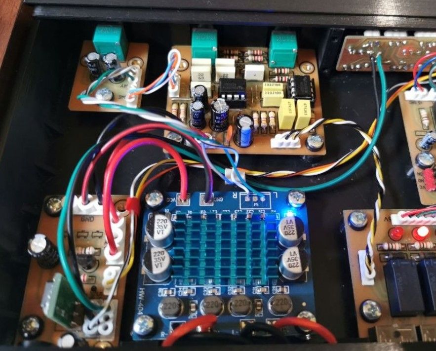
    The speakers are also an important issue, but the truth is that it plays weaker because you believed the Chinese and incorrectly connected the speakers to the module with the TPA3110. You can see that in this photo:

    Inside an audio device showing a TPA3110 amplifier module, wiring, and multiple circuit boards in a case

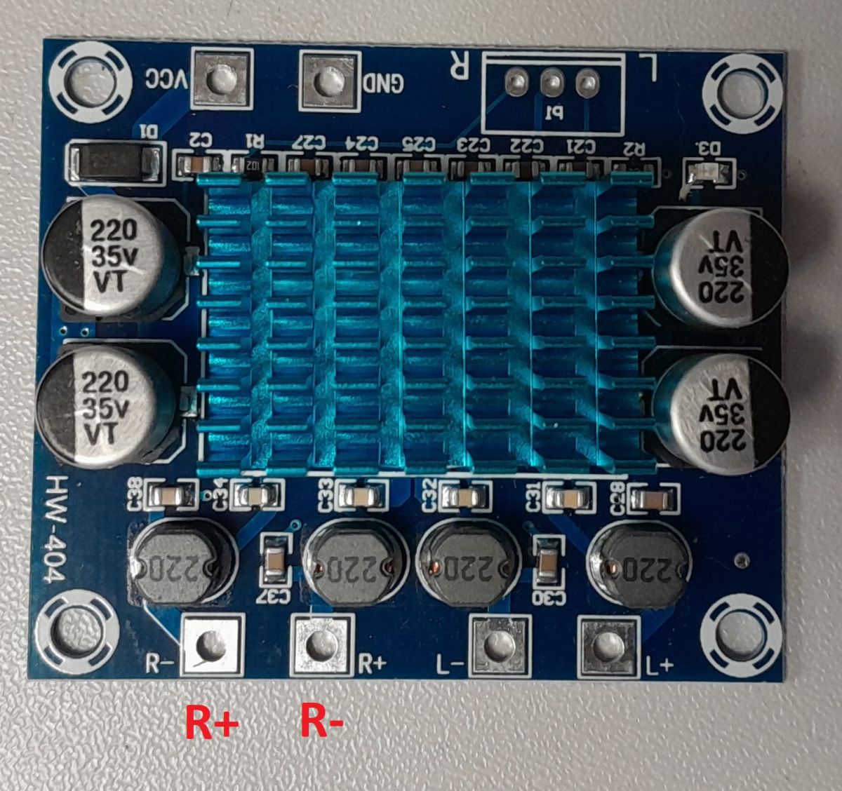
    This module has the wrong output polarity marked for the right channel. The correct one is as I have described in red in the photo below:

    Amplifier PCB with blue heatsink; red labels show correct R+ and R- for the right channel.

    Connect it as I've marked and you'll definitely hear the difference.
    And if you don't believe me, I invite you to read the catalogue note of the aforementioned TPA circuit.


    efi222 wrote:
    I'm putting together something here as a motive for the spectrum, (on request) but somehow these cues are "walking" strangely for me. Or I've got something messed up in my head by the moving bars . Maybe someone can guide me?


    In my opinion, such displayed "wipers" are for nothing. If I were you, I'd stay with a bar analyser.
    Such a thing is not a substitute for real "outriggers" a share :)
  • #39 21900742
    efi222
    Level 21  
    Posts: 727
    Help: 12
    Rate: 1183
    Audio technology is a rather heavy subject for me. In my career, I built a "40 W low distortion amplifier" from Radio Electronics in a bygone era. Older people probably remember it. It played very nicely in my opinion.

    I had no idea at all for the amplifier in the topic. So I did as I did. It would have to be designed by someone more experienced. It sounds tolerable.
    The fact that there is not much space in the enclosure.

    And with the polarity marking of the TPA outputs. Interesting point. Why shouldn't I believe that Chinese has reverse labeled them? I've already encountered all sorts of flowers in their modules. Thanks for pointing this out.

    Regarding the "wipers", it's an on-demand effect, as I wrote. Personally, I would stay with the white pillars, as they fit best with the overall design in my opinion.

    But it's a bit of a trend to go for visual water features, I guess.
  • #40 21900811
    austin007
    Level 17  
    Posts: 762
    Help: 6
    Rate: 271
    I don't know if I missed it, but what and how do you make the transparent panels for the displays? Is it cnc, printing? Out of what material? Great quality case and sense of aesthetics. Congratulations.
  • #41 21900813
    tytka
    Level 23  
    Posts: 753
    Help: 8
    Rate: 1831
    efi222 wrote:
    In my career, I built a "40 W low distortion amplifier" from Radio Electronics in a bygone era. The older ones probably remember it. It played very nicely in my opinion.


    Hmm, the project you mentioned, at one time was very often made by many electronics engineers, including homebrewers.
    I myself also once committed an amplifier with terminals based on this schematic :) ( Link )
  • #42 21900837
    pustan
    Level 19  
    Posts: 645
    Help: 17
    Rate: 1687
    I won't comment on the technical side of the project. I just don't know much about it, But the workmanship, as for me, is top notch. A beautiful kit without any unnecessary bits and pieces. A 5 with a plus. ;-)
  • #43 21900849
    efi222
    Level 21  
    Posts: 727
    Help: 12
    Rate: 1183
    austin007 wrote:
    from what and how do you make the transparent panels for the displays? Is it cnc, printing?

    Not sure I understand the question correctly.

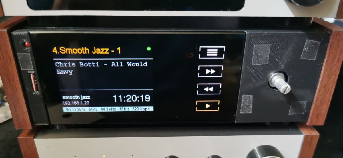
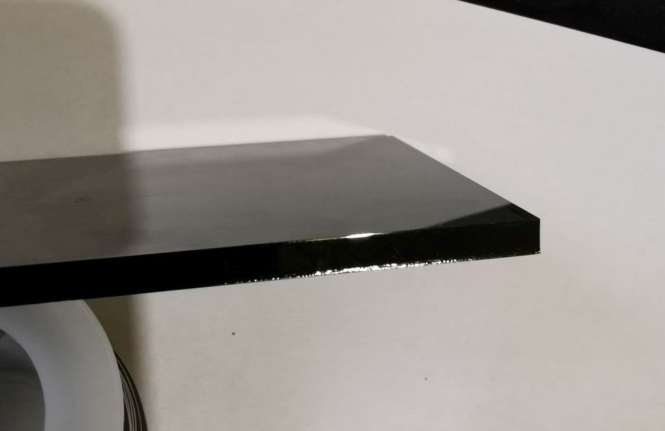
    The picture shows the front of the radio without the masking panel. The display is behind the tinted glass. So-called anisol black 4mm. I often use this glass. The plexi unfortunately scratches over time and here there is always a glass shine :D
    DIY micro tower (desktop version)
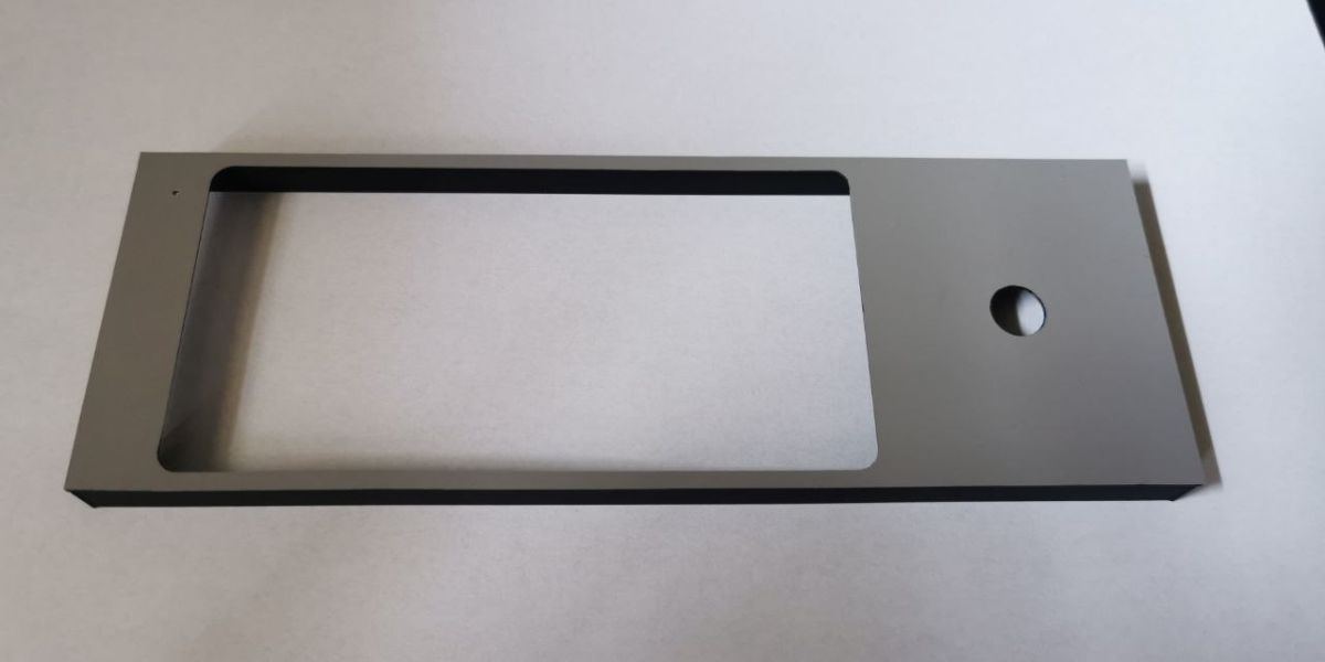
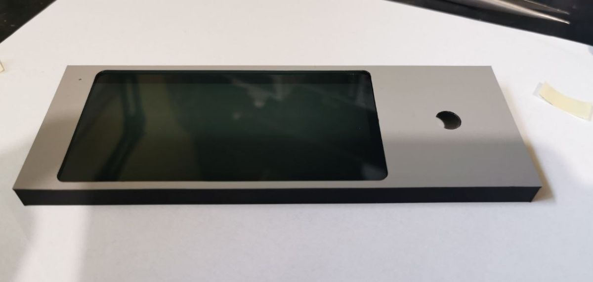
    And here is the masking panel itself. It's a printout taped to the front side with self-adhesive foil in grey. It is attached with contact adhesive. It can be removed quite easily and replaced with, for example, a black panel :) or any other colour.
    DIY micro tower (desktop version)

    tytka wrote:
    I myself also once committed an amplifier with terminals based on this schematic (Link)

    I know your projects. As always full professionalism and very careful finishing :)
  • #44 21900925
    tytka
    Level 23  
    Posts: 753
    Help: 8
    Rate: 1831
    @efi222 Thanks, but I too see a lot of professionalism in this project of yours and great attention to detail and finishing of the project. I am also very aware of how much time you have spent on it.
    For that I bow my head firmly and lowly.
    Because these are values not often found these days. Not many projects like this today.
  • ADVERTISEMENT
  • #45 21900952
    sq3evp
    Level 39  
    Posts: 6445
    Help: 212
    Rate: 849
    The project is interesting. It can inspire more people I think.
  • #46 21901030
    Damian_Max
    Level 21  
    Posts: 395
    Help: 40
    Rate: 96
    Congratulations on the project, it looks great! I'm also getting together to design this internet radio, but something is dragging xD.

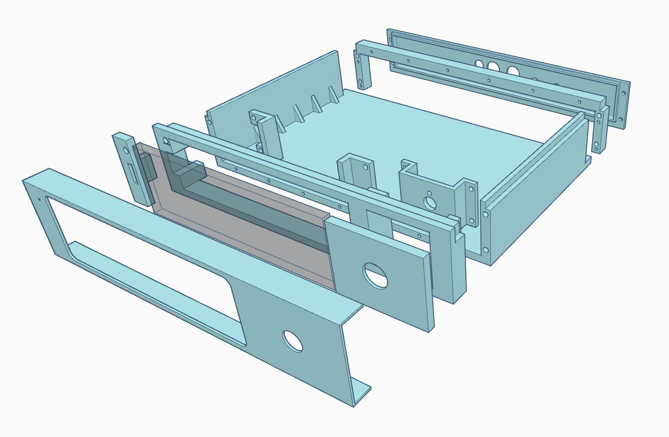
    I really like the printed chassis, if I understand that blue projection correctly, the components on it; are printed in different directions (if I may say so), making it just fold over after printing (without having to cut the filament supporting the 'hanging' components). It may be nothing revelatory in 3D printing, but it impresses me :-) .
    DIY micro tower (desktop version)
  • #47 21901067
    efi222
    Level 21  
    Posts: 727
    Help: 12
    Rate: 1183
    tytka wrote:
    in this your project a lot of professionalism and great attention to detail and finishing of the project

    Thank you very much...

    All of you thank you for your positive reviews , feedback and advice :)

    @Damian_Max
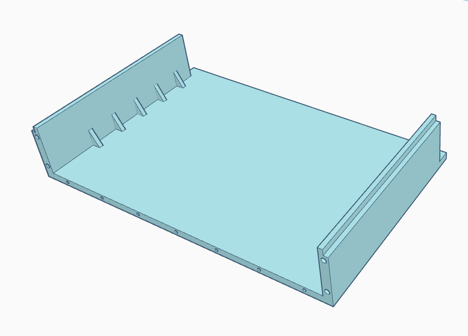
    The picture shows the structural arrangement of the spectrum housing components.
    The components are printed in various positions on the table. They do not have supports or bridges. Of course, you have to scrape something in there - if only the "overfill" of the first layer or the remnants of the island. But something for something. Some have to be glued together (a few recessed pegs to make it easier to fit). You could probably simplify the prints by using bridges or sub-bases, but such a base, for example, is universal.
    3D model of an enclosure base with two side walls and screw holes along the edges
    The same is for the spectrum and amplifier and probably for the BT audio module. The final of the enclosure depends on the "arming" of the front bezels final glued in (something I may come up with to make them screwed in). The rear panel is fixed with screws.
    The top cover of the enclosure is universal and interchangeable with all enclosures. The one from the amplifier has additional ventilation holes.

    In any case, such an enclosure can be made in several ways.

    Damian_Max wrote:
    I am also getting together to design this internet radio

    dIY internet "radios" are a handful on the internet. There are plenty to choose from. :)
  • ADVERTISEMENT
  • #48 21901513
    speedy9
    Helpful for users
    Posts: 12021
    Help: 1231
    Rate: 2416
    Beautiful work. @efi222 have you thought about adding a Spotify Connect option? There's a library on ESP
  • #49 21901515
    robgold
    Level 23  
    Posts: 722
    Help: 10
    Rate: 289
    >>21901513 Which library is my colleague talking about because I think they all require an API key to be entered later in the code and a premium account. So far I have only tested one fully working one but its implementation is not that simple. Maybe I have missed something interesting?
  • #50 21901520
    bsw
    Level 22  
    Posts: 681
    Help: 4
    Rate: 720
    I really like this design. Interesting design - seemingly "just a 3d print" but thanks to the glass panels and wooden sides it looks very tasteful.
    The interior is also ok.

    I have also made a few audio devices myself (file players or mini-music players). The most fun was always in preparing the case - aesthetically pleasing and functional. Nowadays, 3d printing makes this work easier - there is not so much dust and chips, although it probably also takes time - designing in front of a computer.
    I defend myself against this technology and remain analogue :-)

    TechEkspert wrote:
    It is very easy to add FM radio reception capability. A miniature stereo receiver module controlled over I2C gets the job done.

    FM in a device standing on a desk and connected to the net makes no sense. Instead of a few or a dozen humming stations on the air we have thousands of them and from all over the world!
    BTW: I believe that aerial radio and takoważ TV are declining technologies. I don't know why the state spends money on this - they should close down the decommissioning that has started ;-) as soon as possible

    DJCheester wrote:
    It begs for an infrared remote control.

    A remote control would be nice for at least some of the most important functions - switching on, volume or changing stations or visualisation mode - but does it have to be hardware?

    lopr_pol wrote:
    Why does anyone need fm these days, to listen to commercials every 5 minutes plus music pap for the masses?
    Instead of a remote control get control from www.


    I fully share the above comment. With ESP on board you can easily implement an http service and make a page of buttons. Then there is no problem looking for the remote control and aiming :-) Plus backlighting - additional information - dynamic design etc.
    Helpful post? Buy me a coffee.
  • #51 21901521
    speedy9
    Helpful for users
    Posts: 12021
    Help: 1231
    Rate: 2416
    @robgold I did not implement. I've been looking for such an option because it's something missing from such players. There is cspot (https://github.com/feelfreelinux/cspot), which squeezelite (https://github.com/sle118/squeezelite-esp32#spotify) uses.
    I don't know how it works in practice, unfortunately I don't have time at the moment to figure it out.
  • #52 21901558
    Olkus
    Level 32  
    Posts: 3920
    Help: 132
    Rate: 917
    efi222 wrote:
    That leaves a spectrum analyser, I guess.


    You probably could. Although I thought for a while about displaying what is currently being played. But it's not that simple (for me, anyway) so it's just a loose thought :)

    Regards,
    A.
  • #53 21901584
    efi222
    Level 21  
    Posts: 727
    Help: 12
    Rate: 1183
    bsw wrote:
    The most fun has always been in preparing an enclosure - aesthetically pleasing and functional.

    Enclosures have been a bugbear of ectronics designers since the dawn of time.... :)
    bsw wrote:
    I defend myself against this technology and remain analogue

    Which is a pity because the printer makes the job easier. I'm practically done visiting markets in search of structural components.
    Of course, plastic prints are not suitable for all constructions and will not replace more durable steel or aluminium components and housings. But it is something for something.

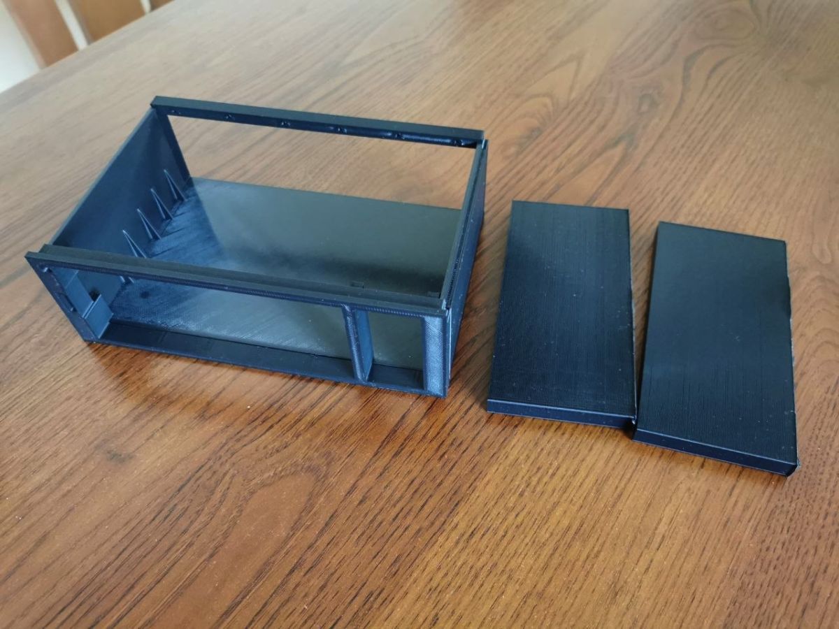
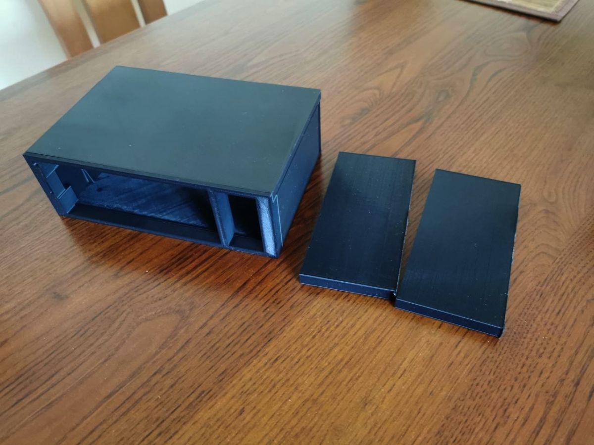
    For those who don't print. Photos of the raw casing for the radio with sides. Now you have to turn on manual beautification mode :)

    DIY micro tower (desktop version)
    DIY micro tower (desktop version)


    Olkus wrote:
    Although I was thinking for a while about displaying what is currently being played.

    This is possible as long as the sound source sends this information.
  • #54 21901588
    ArturAVS
    Moderator
    Posts: 26136
    Help: 2295
    Rate: 7745
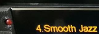
    @efi222 I have a question from a different angle, you write that the front panel is smoked glass. How did you chamfer the edges?
    Close-up of a display showing yellow text “4. Smooth Jazz” next to a red button
  • #55 21901609
    efi222
    Level 21  
    Posts: 727
    Help: 12
    Rate: 1183
    ArturAVS wrote:
    I have a question from a different angle, you write that the front panel is smoked glass. How did you chamfer the edges?

    >>21900849
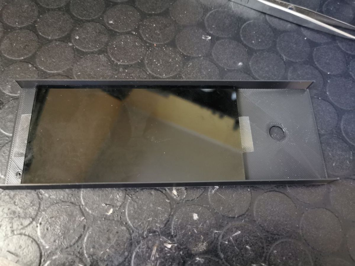
    In this photo the ground edge is done by a glassblower (machine cut). I cut this glass from a larger piece. This is very difficult to do at home without the right tools. I then ordered the glass cut to size from a glassblower. The problem is that not every glazier can do this with such small formats (edge grinding). You need a machine to grind small formats. So I ordered only cut ones. And I just dulled the edges myself with sandpaper so they wouldn't cut. The edge grinding is not really necessary in this construction, as it is concealed.
    It is not even worth cutting the glass by yourself. The cost of such a glass is a few zlotys. (ground glass is three or four times more expensive).

    DIY micro tower (desktop version)
    Small glass pane in a black plastic frame on a textured rubber work mat
    Gray panel with a large rectangular dark window and a small round hole on the right
    9bf170d5b
  • #56 21901611
    ArturAVS
    Moderator
    Posts: 26136
    Help: 2295
    Rate: 7745
    Thanks.
  • #57 21901705
    pepepe1
    Level 13  
    Posts: 77
    Rate: 128
    Fellow Efi, I would make myself such a spectrum, but.... i don't really know which ESP board to use? N16R8 44 pin will be OK? Thank you in advance and best regards.
  • #58 21901726
    efi222
    Level 21  
    Posts: 727
    Help: 12
    Rate: 1183
    >>21901705
    For the ESP32 Wroom 32 or later ESP32 Wroom 32D spectrum
    Conditions for correct compilation are given at the beginning of the source code.
  • #59 21901729
    DJCheester
    Level 28  
    Posts: 2071
    Help: 75
    Rate: 951
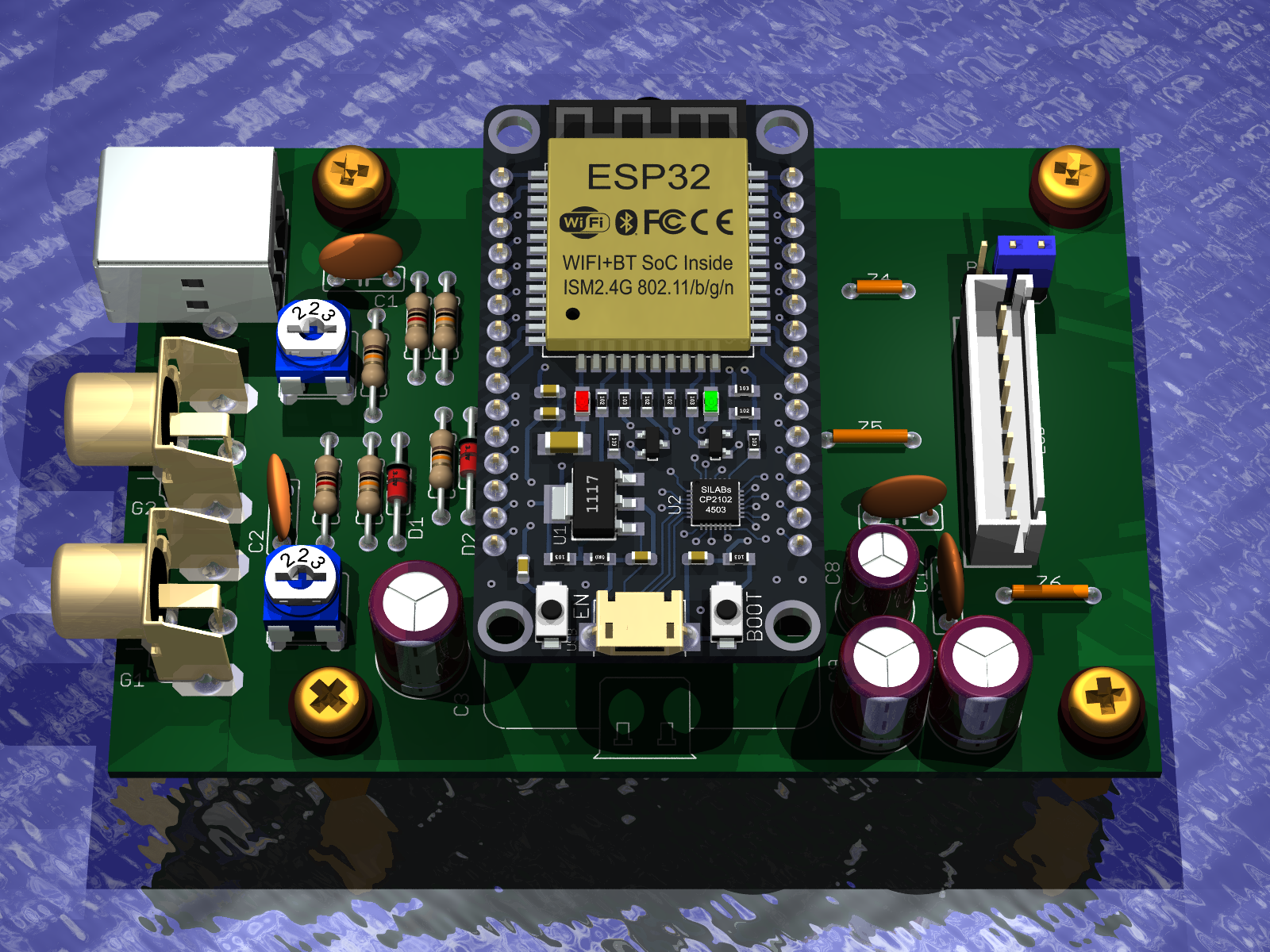
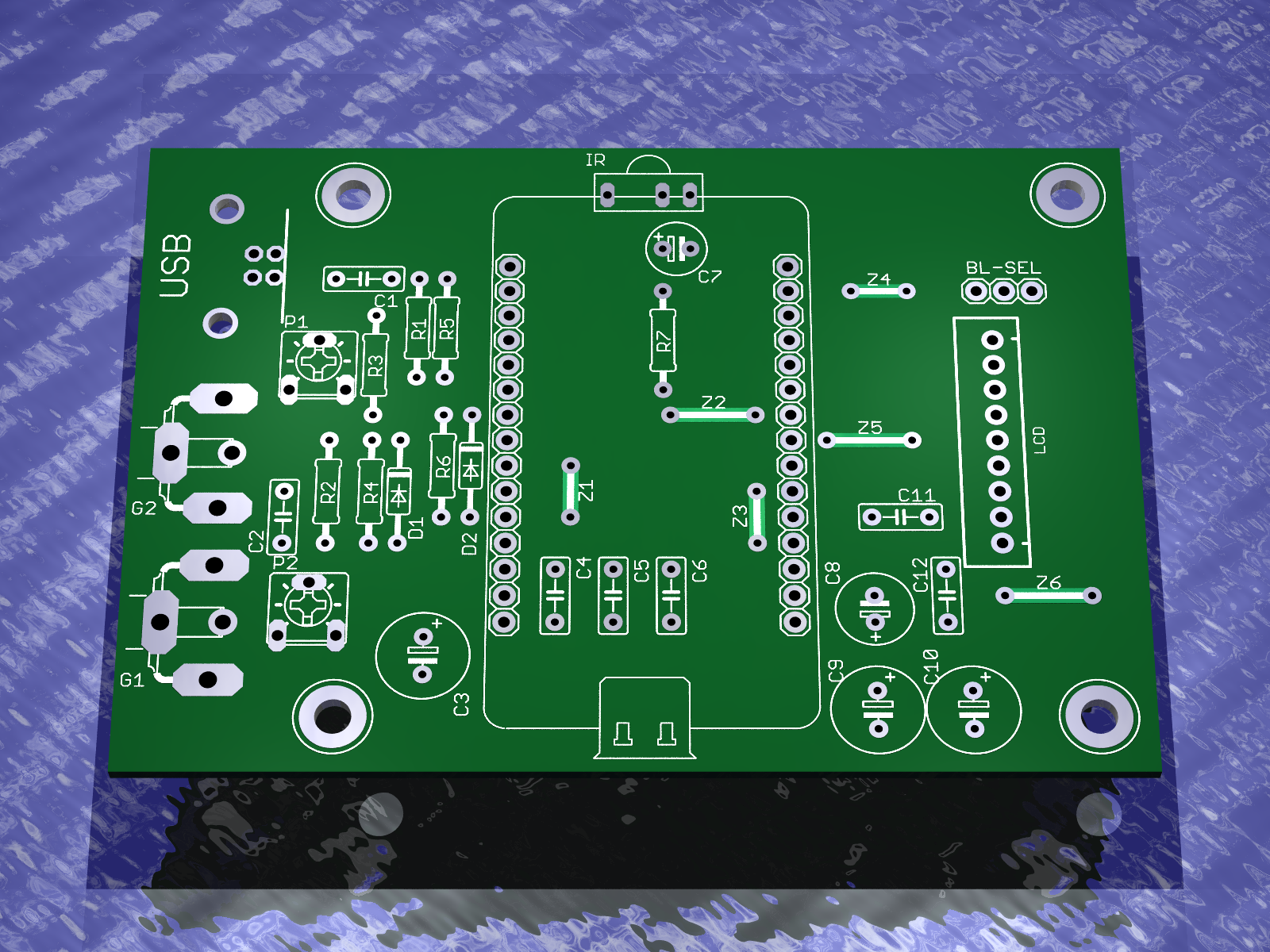
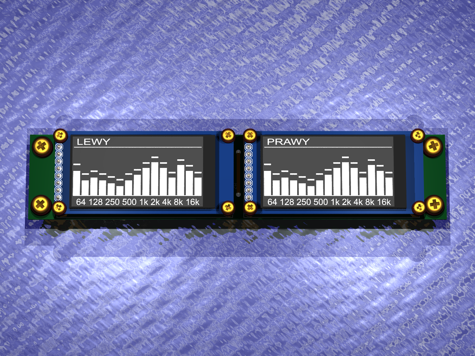
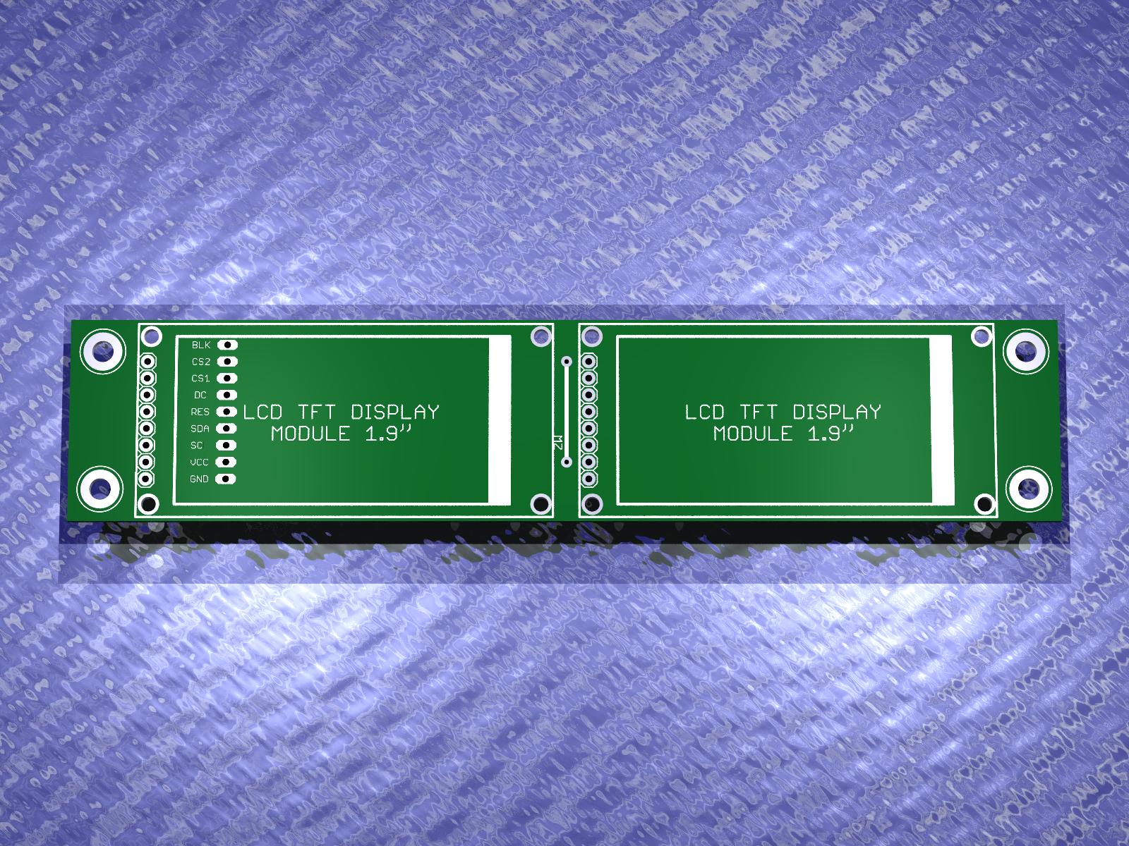
    I did (courtesy of colleague efi222 - thanks for the soft)

    I also made the PCB under this spectrum.

    DIY micro tower (desktop version)

    DIY micro tower (desktop version)

    DIY micro tower (desktop version)

    DIY micro tower (desktop version)

    Greetings....
  • #60 21901735
    efi222
    Level 21  
    Posts: 727
    Help: 12
    Rate: 1183
    >>21901729
    In the newer version from this topic there is still a button for AP mode for wireless software updates and an encoder is connected to change the display themes. As per the attached diagram.

    Added after 11 [minutes]:

    >>21900390
    A newer version of the spectrum with a level indicator motif will be released soon, ;)
ADVERTISEMENT