logo elektroda
logo elektroda
X
logo elektroda

[T34 ] Teardown & Flashing Guide for Aoyan Tuya Smart Plug (EU)

auntlydia 7449 19
ADVERTISEMENT
  • #1 21388711
    auntlydia
    Level 10  
    Hi all,

    I want to share a teardown and flash experience for a device I couldn't find in the database so far. It's a single on/off power socket WiFi switch with power monitoring feature.

    Tuya Smart Plug (EU)
    Manufacturer: Aoyan
    Chip: T34 (same setting as BK7231N)
    Connection: WiFi

    bought here: https://de.aliexpress.com/item/1005006777059625.html


    Tuya 16A Smart Plug packaging with manufacturer details. WiFi Smart Plug package lying on a wooden surface, seen from a side perspective. White smart plug with packaging on a wooden table White smart plug and its packaging on a wooden table.


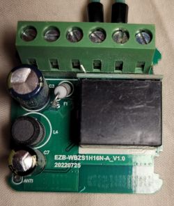
    After usual disassembly for this device type (best working with a pipe wrench on all 4 corners at the top), I was quite surprised to find a different PCB layout without separate module - just a T34 chip without any test solder points and antenna integrated in the mainboard - note that on the following photo, the T34 chip has already been removed, it sits where the 4 big ground pads are located:


    Close-up image of a blue PCB with a BL0942 chip and other electronic components.

    I found some useful information about the chip and how to deal with it here: https://www.elektroda.com/rtvforum/topic4036975.html
    - so I did following steps:
    1. desoldering the chip with hot air
    2. tracing back possible solder points for GND, 3V3, TX & RX
    3. either flashing the chip desoldered and then put it back or, soldering it back first and then flashing
    4. setting up OpenBK firmware

    I share some photos of the important places:

    Close-up of a PCB with removed T34 chip, showing solder pads and traces. Close-up of a PCB with the T34 chip removed. Close-up of the BL0942 chip on a blue circuit board.

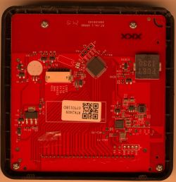
    The tracing back resulted in following finding: all points can be easly accessed via connected BL0942 chip (I assume power monitoring chip):

    Close-up of a PCB with marked soldering points.

    By connecting 4 wires to the mentioned points (I chose 3 pins at BL0942 chip and 1 convenient big pad for GND) and flashing with OpenBK Flasher (setting to BK7231N), the flashing can be done without need to desolder. I have 4 devices of the same kind, so I used one for analysis and flashed the 3 other ones without any desoldering, very easy. CEN is not necessary, just interrupt 3V3 in the process to reset and start flashing.

    Close-up of a PCB section with T34 chip.

    Last step is finding the pinout - I used OpenBK Web application and found following settings:

    P14 - Rel [Channel 1]
    P24 - WifiLED
    P26 - Btn [Channel 1]

    Comment: The LED on P24 is blue and is optional if required for WiFi connection. There is a red LED as well that is linked to the relay on P14, so this one will automatically switch on and off with the relay.

    EDIT: to enable power monitoring, add 'startDriver BL0942' either to autoexec.bat or startup commands. My autoexec.bat is as follows:
    Spoiler:

    startDriver BL0942
    startDriver NTP
    ntp_setServer xxx.xxx.xxx.xxx
    //replace xxx with your IP address above
    ntp_timeZoneOfs x
    // replace x above with value of your time zone


    I also recommend to set following flags: 2; 10; 25; 38; 40

    Here I also attach the read result.
    Spoiler:
    tuya-plug_...yan_01.bin (2 MB)You must be logged in to download this attachment.


    Hope that this device can be added to the database and hopefully it helps others who bought the same device. Cheers =)
  • ADVERTISEMENT
  • Helpful post
    #2 21388942
    divadiow
    Level 38  
    auntlydia wrote:
    If someone wants to give some guidance or experience on how to assign the BL0942 power monitoring correctly, welcome!


    Have you got 'startDriver BL0942' running in your startup command or autoexec.bat?
  • #3 21390261
    auntlydia
    Level 10  
    Nice! That was easy! Thanks a lot. It's working perfectly now. I didn't know that enabling the driver is enough and there was no need to assign any pins like some other of my switches have with the BL0937.

    I get all important data for energy monitoring in Home Assistant, very useful indeed.


    Energy monitoring data in Home Assistant displaying various parameters.
  • #4 21409603
    arphenon
    Level 11  
    Good morning everyone,
    I would ask you to clarify "CEN is not necessary, just interrupt 3V3 during the reset process and start flashing.". Should CEN be in low state before starting flashing (to GND) or high state and interrupt during startup? On the ESP8266 you should specify a high state before programming if I remember correctly. The T34 datasheet note is modest about CEN. My purchased socket design differs slightly, RX, TX hang in the air but are on the edge, TX leads to the inactive pad. BL0937 is controlled by other pins.

    Greetings
    Close-up of T34 integrated circuit on a PCB.
    .
    Close-up of an integrated circuit on a green printed circuit board.
    .
    Close-up of BL0937 microchip on a circuit board.
    .
  • ADVERTISEMENT
  • #5 21409848
    auntlydia
    Level 10  
    >>21409603 Hi, I just flashed few of those T34 devices with green board (just assuming they are same or similar) and it worked as described earlier and in other post about T34 teardown; I connected one 3v3 to BL0937, GND to big relay pin, and TX/RX directly to the chip on the top right corner. With interrupting 3v3 before flashing it worked with every device, so CEN is really not necessary and it seems not connected to the board circuits.

    You may check this guide:
    https://www.elektroda.com/rtvforum/topic4042412.html#21044837
    it looks like your device or similar one.
  • #6 21410202
    arphenon
    Level 11  
    Hello,
    Actually, just unplugging the ground and plugging it in makes the flasher snap. I had a bit of trouble with the RX, TX pins, I wanted to solder them on molybdenum wire, but they didn't want to catch the tin too much, so ended up with thin copper wires from some braided wire. Now I'm still templating QNCX/bl0937/6, 7, 8, 24, 26, 28, and I'll see if it starts.

    Close-up of a circuit board with thin copper wires attached. QNCX profile with pins
  • #7 21417884
    arphenon
    Level 11  
    Hello,
    However, there is a problem, but not on the socket, but on the LED controller chip LF686C20. The symptom is that the web interface stops responding after about a minute. The chip pings, I can see by the serial that MQTT is transmitting. Admittedly it is not set, but this is a sign that the chip is working. The chip is loaded with openbl602_1.17.822.The story is developmental, as I previously had a driver on bl602l10 (LED driver) and it behaved similarly, I assumed it was broken. It was only with this one on an LF686C20 with identical symptoms that I leaned towards them. I should add that I have two other bl602l20's (1.17.822 2 days, 1.17.601 198 days) and they work stably. Anyone perhaps encountered a similar symptom? I have a snapshot of the serial from startup, however there is nothing suspicious there, particularly when the chip is rejetting.

    LED controller with integrated circuit and connected wires. .
  • #8 21702688
    Kisa_ua
    Level 1  
    Hello,
    I've bought my socket on AliExpress under the name Girier, Model JR-PM10. Looks the same as the images in the original post, only in green color.
    But connected in the same way doesn't work for me. I have to change the ground and solder it to the BL0942 chip. And it works perfectly!
    Thanks, author of the post!
    Attachments:
    • [T34 ] Teardown & Flashing Guide for Aoyan Tuya Smart Plug (EU) IMG_4286.jpg (52.47 KB) You must be logged in to download this attachment.
    • [T34 ] Teardown & Flashing Guide for Aoyan Tuya Smart Plug (EU) IMG_4285.jpg (69.2 KB) You must be logged in to download this attachment.
    • [T34 ] Teardown & Flashing Guide for Aoyan Tuya Smart Plug (EU) IMG_4284.jpg (105.06 KB) You must be logged in to download this attachment.
  • #9 21704674
    auntlydia
    Level 10  
    >>21702688 Thanks for your post. Stangely enough, I had the same issue when I flashed it recently and it seems that the ground connection point that I originally suggested in the above photos doesn't work, and it worked for me when soldering it directly to the BL0942 chip as well. So thanks for updating the post, please everyone who has this device, try the direct points of the chip if you face issues, and it should work.
  • #10 21724577
    Tilator
    Level 12  
    I got this a couple days ago. It's the same. Well - almost the same. It seems to me, they don't connect RX and TX to power chip any more and I can't see if it is BL0942 or BL0937
    Printed circuit board with electronic components held in a hand

    Edit: Zooming large enough does give it BL0937.
  • ADVERTISEMENT
  • #11 21741840
    Tilator
    Level 12  
    Here you have one more version of this device:

    Electronic circuit board with connectors held in a hand

    the chinese have made it impossible to connect RX/TX nicely, but as you can see, my good ol' Dremel made some magic to expose those pads.

    Here is my flashing rig:

    Wires attached to a transparent tube with thin metal rods on white paper

    and I took backup first. I try to attach it here too:
    Attachments:
    • readResult_BK7231N_QIO_2025-05-11-00-20-26.bin (2 MB) You must be logged in to download this attachment.
  • #12 21744812
    auntlydia
    Level 10  
    >>21741840 Yea, I came across another model that was aforementioned in another post about T34 sockets that didn't have the RX pin traced to anywhere - for me, it worked with gentle soldering of a very thin wire to the excess solder of the chip's bottom pads. One shall be lucky to receive a socket that exposes pins or pads directly.

    Close-up of a chip on a PCB with labeled GND, TX, RX, and 3V3 pins

    Really awesome to know the trick with the Dremel! I wouldn't have thought of that, and in some cases it might be a good alternative to desoldering the whole chip. If I ever come across a tricky one, I will try it out. Thanks for sharing this!
  • ADVERTISEMENT
  • #13 21809420
    markusb68
    Level 3  
    Hello, I have exactly the same board as in the 1st post with a BL0942.
    I could read the config and flash version 1.18.245 for BK7231N.
    The Tuya config I could read out looks like this:
    Microcontroller pin configuration interface with assigned I/O functions
    This is my autoexec.bat: "backlog startDriver NTP; ntp_setServer 192.53.103.108; ntp_timeZoneOfs 1"
    And my main screen looks like this:
    Control panel of OpenBK7231N device showing status and energy readings
    But when I try to calibrate the BL0942 I see these errors in the log:

    Error:EnergyMeter:Calibration incorrect - connect load first.
    Info:CMD:[WebApp Cmd 'VoltageSet 235' Result] Command found but returned error
    Error:EnergyMeter:Calibration incorrect - connect load first.
    Info:CMD:[WebApp Cmd 'CurrentSet 0.86' Result] Command found but returned error
    Error:EnergyMeter:Calibration incorrect - connect load first.
    Info:CMD:[WebApp Cmd 'PowerSet 200' Result] Command found but returned error
    

    A 200 W resistive load (PF = 1) is connected and the relay is ON.

    What can it be?

    Do I have to set something for P10 & P11 (RX/TX) to get the communication with the BL0942?
    Besides, I have read here that there are no settings for BL0942 needed in the module configuration.

    EDIT: I found this in the log after restart:
    
    Info:CMD:CMD_StartScript: started @startup at the beginning
    Info:CMD:CMD_StartScript: started autoexec.bat at the beginning
    Info:MAIN:Main_Init_After_Delay done
    Info:EnergyMeter:Read ENERGYMETER values sz=32
    Info:MAIN:Started BL0942.
    Info:NTP:NTP driver initialized with server=192.53.103.108, offset=0, syncing every 60 seconds


    Does it mean that it can communicate with the BL0942 ?
    The problem is that I can't access the pins below the T34 to verify the RX/TX lines.
    I have soldered the cables for flashing to the BL0942 - I hope I have not killed the BL0942 while soldering.
  • #14 21815975
    arthur_koba
    Level 2  
    >>21741840 Dear, thanks for sharing your flashing method. I was initially upset when I found out I had the same boards, but I had no choice—desoldering would have taken significantly longer—so I decided to try your method. And it worked. I used a stone bit on my Dremel, so I was able to cut out the part where the UART contacts are. Incidentally, inside the chip, there's a copper layer of GND above them, and by drilling through it, you can access the TX and RX pins. I tinned them without any problem and soldered one tip of each small wire to them, which allowed me to flash the firmware.

    Close-up of soldered wires connected to an integrated circuit on a PCB

    Electronic module with connected wires next to a power strip with sockets
  • #15 21870204
    schaloule
    Level 7  
    >>21741840
    Thanks for the post. I quite easily flashed a couple of Tuya Smart plugs from QNCX as described here https://www.elektroda.com/rtvforum/topic4166348.html, but now I have received a new device which is a variant that doesn't expose the pins anymore to the sides, but has the plastic covering all pins. I hope I will succeed with the dremel trick.
  • #16 21870359
    auntlydia
    Level 10  
    I recently ordered some more plugs and received the revision with T34 and no accessible pads, like @Tilator posted here before. Because of some bad experiences on another chip and board with my dremel tool, I decided to give up on this method and desolder the chip with hot air. But this doesn't always work out for me either, I had some attempts that ended up with dead chips for different reasons, probably they are a bit fragile too and a lot of things can go wrong in that process. Luckily, I was able to use a donor module (I believe it was CBU with BK7231N), and in order to wire it up, I had do do some tracing to find spots that are a bit more convenient to reach for soldering, but of course the chip's pads would have worked too, they are just so very tiny. So I'd like to share the photos of this board's revision and the spots that I chose.

    Close-up of a blue PCB with ICs and a printed antenna; a white plastic housing part on the right. Close-up of a blue PCB with an integrated circuit and connector, held between fingers Close-up of a blue PCB with a printed antenna, SMD components, and an R001 resistor, held between fingers Close-up of a blue PCB held between fingers, with antenna trace and colored handwritten annotations


    After all, I was able to rescue this plug and it runs perfectly well with the donor module now =)
  • #17 21870421
    schaloule
    Level 7  
    >>21741840
    I did manage to get access to the pins with a Dremel and after a few soldering attempts I managed to successfully flash OpenBeken.
    Alas, I can't find the correct pin definitions.
    My device has a blue Wi-Fi LED and a red relay LED, and the settings which I did use for my earlier sockets do not work.
    The settings from 21388711 for the relay, LED, and button did work, but I can't find the correct setting for the BL0937 chip.
  • #18 21870430
    auntlydia
    Level 10  
    >>21870421 you can see in my photo the pinout:
    P6 - BL0937CF
    P7 - BL0937CF1
    P8 - BL0937SEL
    if your board revision is the same as mine, these settings should work.
  • #19 21870720
    schaloule
    Level 7  
    >>21870430
    In your picture I see a BL0942 and my chip is a BL0937, but your settings did work. Thanks a lot.
  • #20 21871214
    auntlydia
    Level 10  
    >>21870720 there are different revisions of boards with T34 onboard, some with blue PCB, some with green PCB, some have BL0937 and some have BL0942. In my previous reply, I had included some photos of a blue board version with desoldered chip and marked traces, three of the markings say "BL0937.." Please check posts and pictures carefully, it can be confusing ;) Happy if I was able to help.

Topic summary

✨ The discussion revolves around the teardown and flashing of the Aoyan Tuya Smart Plug (EU), which features a T34 chip and power monitoring capabilities. Users share their experiences with disassembly, noting the absence of a separate module and the integrated antenna on the PCB. Key points include the successful flashing process using the BL0942 driver, the importance of interrupting the 3V3 line during flashing, and troubleshooting issues related to the LED controller chip LF686C20, which causes the web interface to become unresponsive. Various users provide insights on wiring connections and the stability of different firmware versions.

FAQ

TL;DR: Aoyan/Girier EU Tuya smart plugs with T34 can be flashed in-circuit (3 units verified) by interrupting 3.3 V; “CEN is not necessary.” [Elektroda, auntlydia, post #21388711] Why it matters: You can gain local control and power monitoring without desoldering, saving time and reducing risk for DIY users and integrators.

Quick Facts

How do I open the Aoyan/Girier EU Tuya smart plug without damage?

Grip the four top corners with a pipe wrench and twist to release the shell. This exposes the main PCB with the integrated antenna and T34. Work slowly to avoid cracking plastic tabs or stressing the relay solder joints. [Elektroda, auntlydia, post #21388711]

Can I flash the T34 without desoldering the chip?

Yes. Solder TX/RX, 3.3 V, and GND, then briefly interrupt 3.3 V to trigger flashing with OpenBK Flasher set to BK7231N. One user analyzed one unit and flashed three others fully in-circuit. “CEN is not necessary.” [Elektroda, auntlydia, post #21388711]

Where do I connect TX, RX, 3.3 V, and GND on these boards?

Use the BL0942 vicinity for easy access: three pins there map to UART and one large pad served as GND on early batches. If GND fails, wire it directly to a BL0942 pin for a reliable reference and flashing success. [Elektroda, Kisa_ua, post #21702688]

Do I need to pull CEN low to flash T34?

No. Reported boards entered flashing after a brief 3.3 V interruption. Authors noted CEN was unused or not tied into board circuits. This simplifies wiring to just 3.3 V, GND, TX, and RX during programming. [Elektroda, auntlydia, post #21409848]

What OpenBeken pin mapping works for this plug?

Set P14 to Relay Channel 1, P24 to WiFiLED (blue), and P26 to Button Channel 1. The red LED follows the relay on P14, so it toggles automatically with switching. Save in the OpenBK web UI after flashing. [Elektroda, auntlydia, post #21388711]

How do I enable power monitoring data in Home Assistant?

Add startDriver BL0942 to autoexec.bat or Startup Commands in OpenBK, then restart. Telemetry appears over MQTT for energy metrics. One user confirmed all key readings visible in Home Assistant after enabling the driver. [Elektroda, auntlydia, post #21390261]

What if RX/TX aren’t exposed or are cut off on newer revisions?

Some newer boards don’t route RX/TX to test pads. Two fixes worked: carefully solder a thin wire to the chip’s edge/bottom pad solder, or Dremel the mask to expose hidden pads before wiring. Take a full backup first. [Elektroda, Tilator, post #21741840]

My ground pad doesn’t work—how do I fix flashing failures?

If case-ground or relay-pad ground fails during flashing, move GND directly to a BL0942 GND pin. Multiple users reported immediate success after relocating GND there. This change resolved connection errors in OpenBK Flasher. [Elektroda, auntlydia, post #21704674]

I only have BL0937 in my unit—does the method change?

Flashing via 3.3 V interrupt still works. Some green-board units used BL0937 and routed TX to an inactive pad, requiring direct chip soldering for UART. Verify the metering IC marking before configuring drivers. [Elektroda, Tilator, post #21724577]

Quick 3-step: how do I flash T34 with OpenBK?

  1. Wire 3.3 V, GND, TX, RX; choose solid GND (preferably BL0942 GND).
  2. In OpenBK Flasher, select BK7231N and your COM port.
  3. Power 3.3 V, briefly interrupt it, then start flashing; set pins and startDriver BL0942. [Elektroda, auntlydia, post #21409848]

What is Tuya in this context?

It’s the original cloud-based ecosystem these smart plugs ship with. The thread devices are Tuya-branded plugs re-flashed to run OpenBeken locally, removing cloud reliance while keeping Wi‑Fi control and metering. [Elektroda, auntlydia, post #21388711]

What is OpenBeken (OpenBK)?

OpenBeken is the community firmware used on T34/BK7231-class devices. It provides local control, MQTT, and drivers like BL0942 without Tuya cloud. You configure pins and drivers in its web UI. [Elektroda, auntlydia, post #21388711]

Any stability stats or long‑run results shared?

One user reported BL602L20 devices running OpenBL602 for 198 days and 2 days, respectively. While different silicon, it shows strong uptime potential under similar community firmware workflows. Track your own results post‑flash. [Elektroda, arphenon, post #21417884]

The web UI freezes after a minute—what should I check?

An edge case on LED controllers (LF686C20 with openbl602_1.17.822) showed UI hangs while ping and MQTT stayed alive. Try another firmware build, or disable the LED driver to isolate the issue. Back up configs first. [Elektroda, arphenon, post #21417884]

How do I back up before experimenting with pads or Dremel work?

Create a full flash backup as soon as UART is working. One user built a rig, exposed hidden pads with a Dremel, and dumped firmware before proceeding. Store the backup safely for recovery. [Elektroda, Tilator, post #21741840]

What tools and materials did users find helpful?

Pipe wrench for opening, thin copper wire for fine pads, hot air for desoldering when needed, OpenBK Flasher, and a Dremel to expose masked RX/TX pads on locked revisions. Flux and magnification help a lot. [Elektroda, auntlydia, post #21409848]
ADVERTISEMENT