Hello.
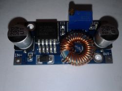
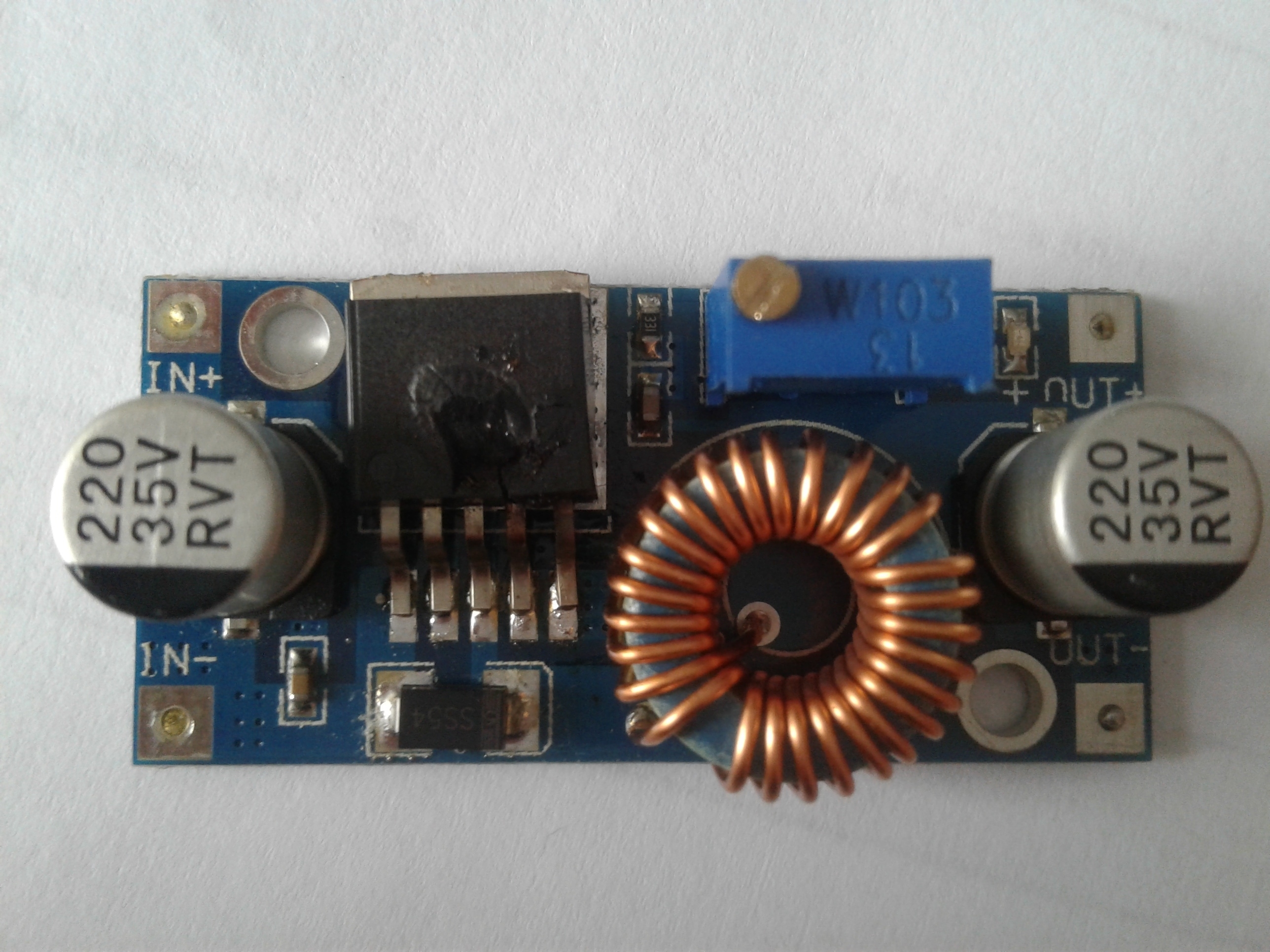
Below I present a description of the step-down converter based on the XL4005E1 chip.
The prices of the converter start on Aliexpress from less than $ 0.95 with shipping, prices with shipping on Polish auction portals start from about PLN 12.
The maximum input voltage for the converter is 32V DC.
The output voltage is regulated with a multi-turn potentiometer in the range from about 0.8 to 30 V, current efficiency up to about 5 A. Operating frequency 300kHz, drop out about 0.6V, built-in thermal, short-circuit and overload protection.
Converter dimensions: 43 x 21 x 14 mm
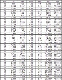
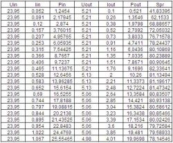
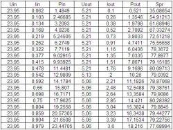
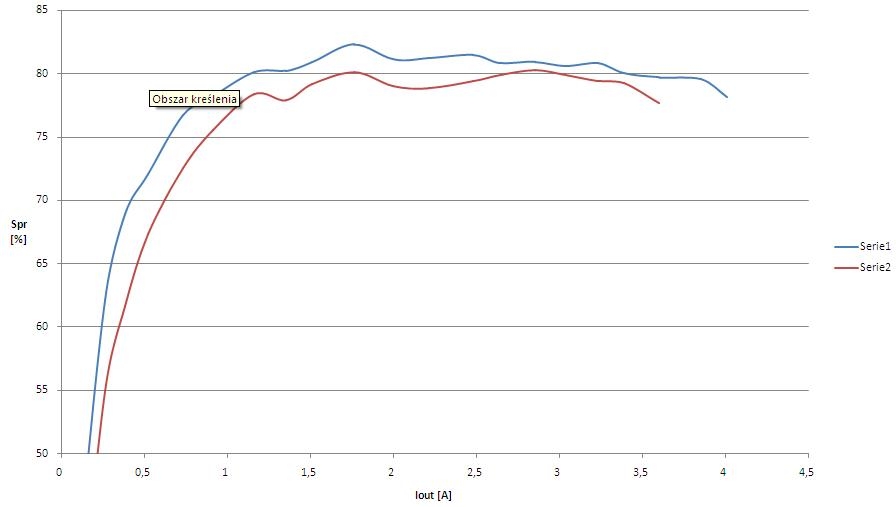
The converter was tested with an artificial load for input voltages of 12 and 24 V and for output voltages of 5 V. During the tests, the voltages and currents on the input and output sides of the converter were measured, and the power and efficiency were calculated.
Below I present the measurement results.
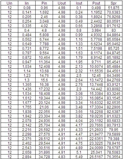
Input voltage 12V, output voltage 5V:
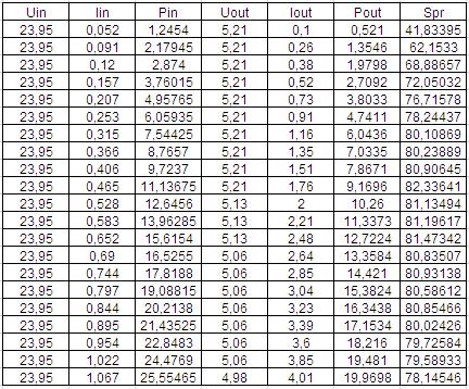
Input voltage 24V, output voltage 5V:
Fitness graph:
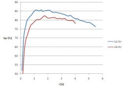
It can be seen that the efficiency of the converter depends on its supply voltage, in this case the lower the supply voltage, the higher the converter efficiency.
When performing the above measurements on an artificial load, during the load change, I turned the load control encoder too much, which resulted in the load of the converter with a current of over 7A for a few seconds, which caused its damage. It was not accompanied by any special effects, just the blue LED on the converter board went out. In the idle state, the maximum output voltage after damage is about 1.5V, but after applying a load, the voltage at the output disappears. The XL4005 chip and the Schottky diode were damaged.
As there were supposed to be more measurements, I decided to buy another converter and repeat the unfinished measurement with 24V input voltage and 5V output voltage, and also make measurements for other voltages. The second inverter was purchased from another vendor.
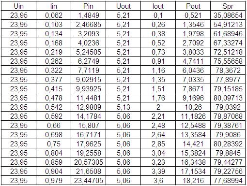
Here are the results of the repeated measurement for the new converter - 24V / 5V:
Measurements could not be completed. As you can see, with a load of 3.6A, after a dozen or so seconds it sizzled, hissed and there was smoke with an unpleasant smell of burning electronics.
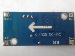
The effect of this can be seen in this photo:
There was a hole in the XL4005 chip, and the Schottky diode was damaged as in the previous converter as a result of too much load.
Both converters were tested with exactly the same equipment and with the same voltages, but between the two copies you can notice a difference in efficiency, although at first glance they look identical.
Below is a comparison of the efficiency of these converters for 24 / 5VDC voltages:
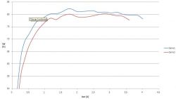
Series 1 - the first converter damaged by excessive load, series 2 - the second converter where a hole was created in the circuit at 3.5A.
Despite the built-in security features, neither of them had worked.
The temperature did not exceed 40 ° C during these tests.
I damaged the first inverter myself by loading it too much, which showed that the overload protection did not work, the second one damaged by itself at a load of about 70% where the temperature of the system did not exceed 40 ° C.
I don't know if I came across a flawed copy or if it was some inept fakes.
Maybe someone who has such a converter will write his experience of using it.
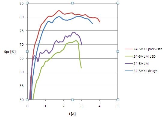
Below are links to the descriptions of two other DC-DC step-down converters on the LM2596 chip, where one has a built-in voltmeter to measure the input and output voltage.
https://www.elektroda.pl/rtvforum/topic3420289.html#16966161 https://www.elektroda.pl/rtvforum/topic3420290.html#16964656 Below is the efficiency diagram for the input voltage of 24VDC, output voltage of 5VDC for the converter based on the LM2596 system, the converter based on the LM2596 system + built-in measurement of the input and output voltage and two converters based on the XL4005 system tested in this article:
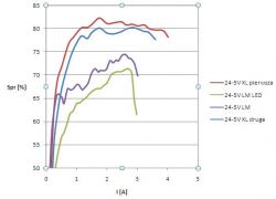
It can be easily seen that the converters based on the XL4005 achieve the best efficiency.


Comments
There is one fundamental problem with these Chinese converters, they spread like stupid, without any problems the interference they generate reaches the FM radio band :roll: [Read more]
The user of grala1 helps me a lot by testing the electronic modules. As soon as I found out that his converter burned down during the tests, I immediately sent a new one. It turned out that the second... [Read more]
At most auctions in Poland with such converters it is written to use a heat sink, so there must be something in it :P [Read more]
Since col. @ grala1 I am testing modules, maybe I will propose DPS converters. At the end of November 2017 I bought a DPS5005 in the GoTronik store, it did not regulate the voltage at all, in the... [Read more]
It would not have had time to remove the heat if the demand for electricity increased rapidly. Besides, grala1 watched the temperature. A protection that did not work should have worked. And it didn't... [Read more]
The same scrap as this: https://www.elektroda.pl/rtvforum/topic3420290.html. A dozen have already added to the basket. [Read more]
I believe that the diode (SS54) used there causes the internal MOSFET to "burn", especially in the event of its short circuit. Datasheet recommends using a diode with an average forward current of 10A... [Read more]
I think that the XL4005 and similar (there is a version for 3A) are ineffective LM2678 (5A) or LM2576 (for 3A) trips. LMs work without any problems, resistant to short circuits and temperature rise. The... [Read more]
As for this short-circuit resistance, I have already managed to make a resistive divider out of one LM (~ 10? ;) . [Read more]
Is the USB DVB-T receiver on RTL2832U with alternative software would it be suitable for estimating the level of noise emitted by the converter? [Read more]
Colleague prosiak_wej had bad luck with this inverter because they are really well done. I have a workshop power supply built on the DPS 5015 module and it works great. I bought it directly from a Chinese... [Read more]
Not only him. I think that if you are lucky this converter works, and if you are unlucky, you come across a fake LM257x and it does not work. I produced about 400 pieces of LM2576 devices, no problems.... [Read more]
Col. @ barti10 - what voltage from the power supply did you give to the converter? Slightly over 50V to get 50V in the output, say 48V and the inverter limited to 45v? [Read more]
XL4015 is in use and doing quite well .... In fact, the XL4005 has a problem and likes to go up in smoke [Read more]
Those who want to squeeze 5A from the 3A max module have a problem. The XL4015 fell to me in the 6A module with current limitation, I changed it to the more powerful XL4012, which does not mean that I... [Read more]
It is a pity that the Chinese did not write about it. Fortunately, I didn't damage my devices, but I lost money and time and time is money. I stay with LM. I prefer to have surprises such as a burnt... [Read more]
Waiting for lot XL 4015. So I can test how it arrives. [Read more]
I am waiting for the tests. Greetings :) [Read more]
And I am waiting for an idea how to get a relatively linear adjustment of the output voltage of the converter on the XL4015. There is a 10-turn peer on the PCB that I desoldered and I experiment with the... [Read more]