Soon in
Elektroda.pl gadgets A kit will appear that allows you to build a simple regulated power supply with voltage and output current readout. Inverter module descriptions
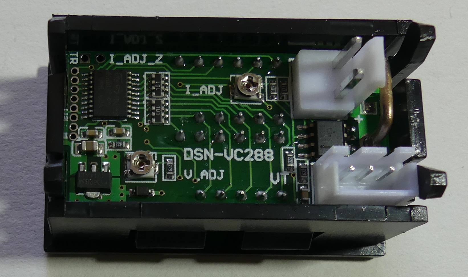
DC / DC buck 9A 300W 1.2V-35V and a panel current and voltage meter
DSN-VC288 can be found at elektroda.pl. After completing the set with a direct current source (e.g. unnecessary laptop power supply, transformer with rectifier and capacitor), you will get a simple regulated power supply. For the convenience of adjustment, the assembly potentiometer can be replaced with a multiturn potentiometer equipped with a knob.
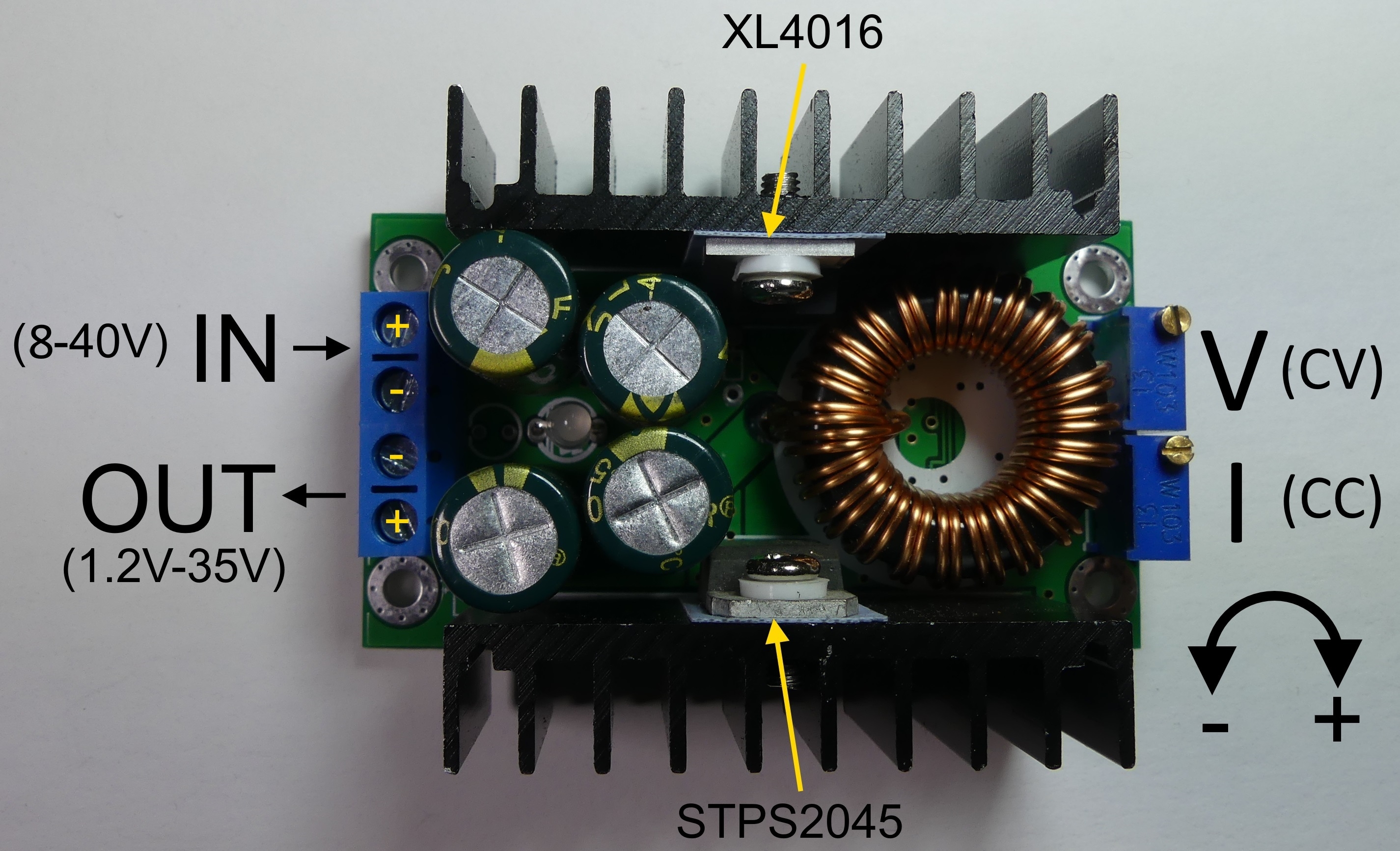
The DC / DC converter, apart from voltage regulation (CV operation), also allows for current limit regulation or CC operation. The impulse converter is based on the XL4016 chip and enables voltage regulation in the range of 1.2V-35V, maximum output current 9A. Input voltage in the range of 8-40V. Details can be found in the description:
https://www.elektroda.pl/rtvforum/topic3434421.html 
The panel meter has a moderate accuracy of indications, we can try to improve it using mounting potentiometers placed on the module's board.
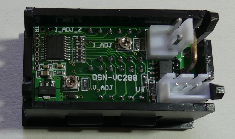
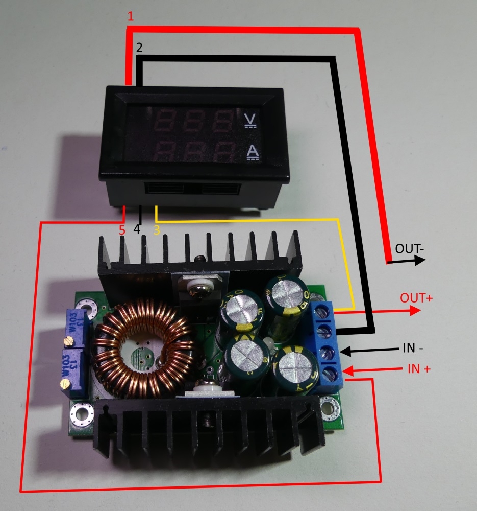
The LED panel meter can be powered from a separate voltage source (or e.g. from an isolated AIMTEC DC / DC converter). Supply voltage is applied to wires 4 (GND) and 5 (+). When powered by 12V, the system consumes a current of about 20mA. Apply the voltage measured in relation to the wire 2 (GND) on the wire 3. Depending on the source, module suppliers provide the permissible supply voltage in the range of 4.5-24V. The system can be powered from the measured voltage or from the voltage at the converter input, then the wire 4 is left unconnected (the mass of the system is on the wire 2).
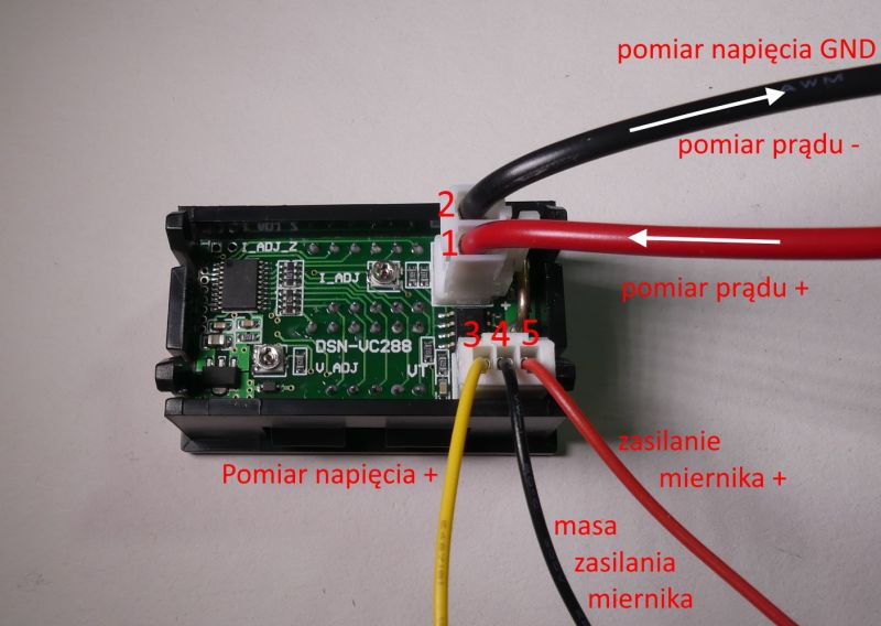
It is important that the voltage supplying the meter does not exceed 24V (other sources indicate 28V or 30V). The converter can work with voltages as high as 35-40V. In such a situation, a stabilizer should be placed in the power supply circuit of the meter (wire 5), e.g. + 12V, the wire 4 is not connected.
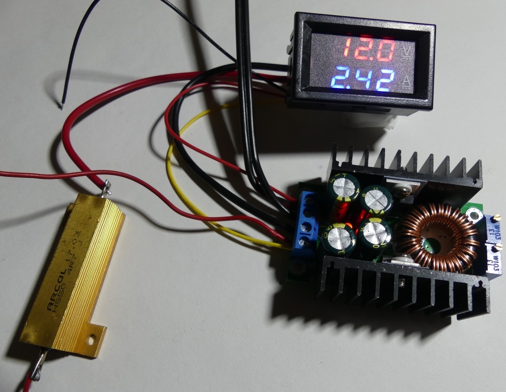
The current is measured in the circuit of the measuring resistor on leads 1 and 2. Below is a diagram of the module connection (for supply voltages up to 24V) and a view of the practically connected modules. A 4.7om resistor simulating the receiver is connected to the output.


It is worth paying attention to the set's output cable, which acts as the output GND. This is the red lead of 1 meter. Be careful not to confuse the polarity as the red wire is usually + power. A comprehensive description of the panel meter can be found here:
https://www.elektroda.pl/rtvforum/topic3444499.html It is worth completing the whole with a housing and replacing both mounting potentiometers of the converter for voltage regulation and current limitation, with multi-turn potentiometers with knobs mounted on the front panel of the housing. It is worth to lead the output voltage to the terminals mounted in the housing. The source of voltage can be a traditional transformer, rectifier and a ripple smoothing capacitor, but you can also use a recycled switching power supply, e.g. from a laptop, printer, etc. The built power supply will have its limitations, but it can be useful in many workshops for "rough" measurements and powering less demanding circuits.
Let me know what results can be obtained with the use of the presented set. 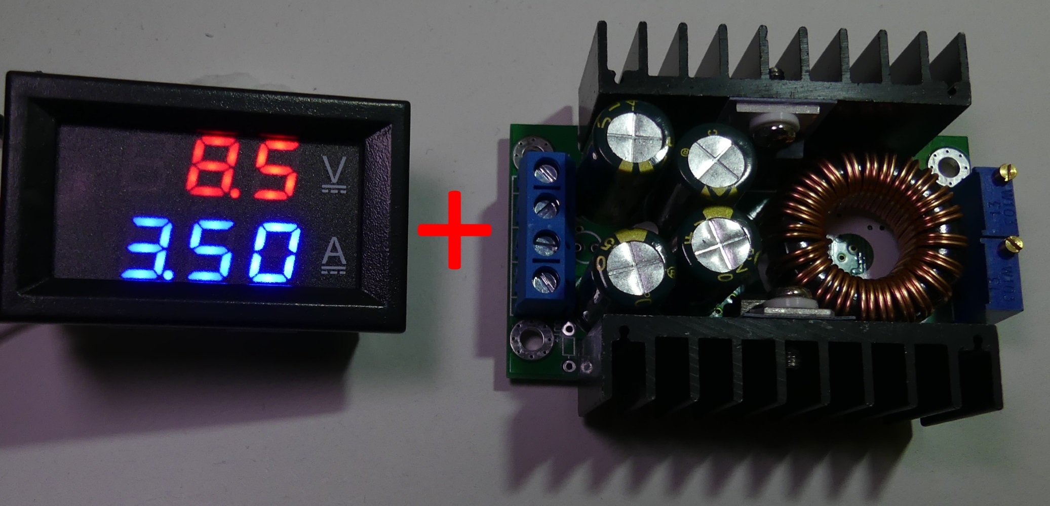


Comments
Some time ago I built a similar circuit to a rectifier (I had a rectifier that gave about 18-20V). It was ok for a quick recharge, but I couldn't leave it all unattended. After installing the converter... [Read more]
If you connect the outputs in reverse, they will probably blow out the capacitors on the inverter output first. Unfortunately, most of these cheap Chinese inverters do not have reverse connection prot... [Read more]
I have the same converter (powered by 2x12V power supplies connected in series, giving max. 24V and about 4A). I, in order to protect against reverse connection of batteries / accumulators to this inverter... [Read more]
In that case, would it be a good idea to add an ordinary rectifier diode in series and connect the voltage measurement after this diode. Let's say a diode at 10-20A. Are there perhaps better options... [Read more]
Medium idea - this diode will emit a lot of heat when we draw high currents from such a "power supply". Besides - the voltage drop on such a diode will be the greater, the greater the current will flow... [Read more]
The solution has been known to mankind for some time, it is just like that perfect diode . [Read more]
And it is not easier to put relays between the converters and the output. Included with the power supply or separately. [Read more]
At the author's request, I am starting a discussion on replacing impractical multiturn peers with "ordinary" potentiometers. Two each for current and voltage regulation. The purpose of this modification... [Read more]
Coarse and fine adjustments are only needed for voltage adjustments. Additionally, the problem of linearity of this regulation (output voltage as a function of the angle of rotation of the potentiometer... [Read more]
No sense,. As a colleague imagines it in the CC mode. Such a scale would be appropriate only for a load with a specific current. See how it is made in factory power supplies. [Read more]
Wait a minute! Why add setting tables, nonlinear scales, PRs and wonders on the stick, since the set voltage can be quickly read from the meter? [Read more]
Well, I said that it makes no sense :) . Whereas: This is a different story. As the settings are often changed to a large extent, the multiturn potentiometer is very inconvenient to use. [Read more]
Besides, expensive. I'm just in favor of PRs, I was a little carried away. With my statement, I just wanted to cut off the unnecessary polemics and punching points :) How can you make a setting table... [Read more]
It is true that in the set with a digital voltmeter the scale is not needed, I agree with that. However, the connection scheme itself requires improvement. The first thing to check is whether leaving... [Read more]
This set is great. I just have some 24V power supplies and I will use it and make a power supply for very lazy people :D [Read more]
Have you done any inverter modification? How do the potentiometers work? ;) [Read more]
Not this one, but I have already used this solution and it works as it should. You can even see them in several of my articles. [Read more]
In such cases, if I often use several voltages interchangeably, I prepare appropriate dividers and select with switches, whether I need one of the previously "programmed" or full manual control. It also... [Read more]
This is what happened to me ... is it a good idea to make a workshop power supply on this converter, and use a switching power supply as a power supply? I need a power supply mainly to play with microcontrollers... [Read more]