A small adapter controls external HDD power from a DVB-T tuner, using either USB voltage or SCART pin 8 as the activation signal.
JP1 jumpers let you choose the trigger source and whether 5V for the drive comes from the tuner or from the U1 stabilizer.
The linear stabilizer can dissipate almost 5W at 0.8A, while 500mA still means 3.5W.
The circuit can switch on the hard disk supply or only the 12V rail, but startup delay can make the drive invisible to the tuner.
Summary generated by AI based on the discussion content.
When the capacity of the USB stick attached to the tuner ceased to be enough for me, I connected an old 2.5 "disk. When it was too small, I connected a 3.5" HD disk. There is a power problem. The power supply and disk had to work all the time when I set to record my favorite program. Almost every tuner has a SCART output, on which pin 8 informs about turning on the tuner. Why SCART Because, depending on the tuner, the USB voltage can always be on SCART when the tuner is active, because this pin controls the TV by switching it to the selected video input. Zasilanie_...ev1337.pdf (11.96 kB)You must be logged in to download this attachment.
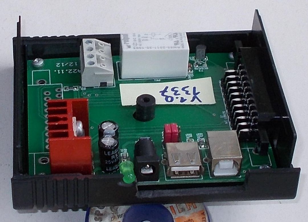
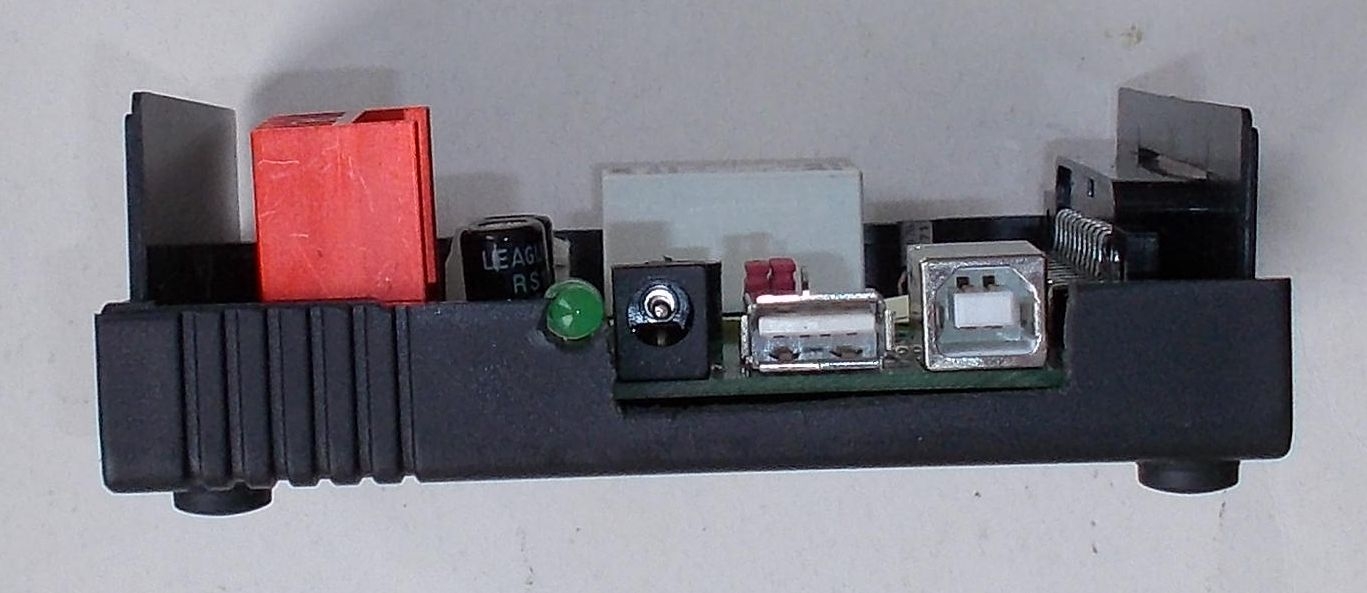
The simple design that I made allows you to switch on the hard disk power supply or the 12V voltage alone. In addition, it contains a stabilizer that produces 5V. Connections on JP1 decide whether the power supply activation signal should be USB voltage from the tuner or SCART connectors. In addition, you can choose whether 5V for HD should come from the tuner or U1 stabilizer. The SCART and USB connector is through. Due to the fact that I do not use SCART, I did not solder the through connector. In addition, the heat sink is a bit disturbing (as I designed the PCB, I was young and inexperienced).
The construction is not very successful. The line stabilizer can give off a lot of heat. At a consumption of 0.8A, almost 5W will separate on the stabilizer. With more economical electronics it is better, 500mA is 3.5W. Undoubtedly, a pulse stabilizer would be better. Another disadvantage, disk or tuner, is that the hard disk needs some time before it is ready to work. If the tuner briefly waits for the drive to be ready, it may not be visible to the tuner. A problem known to some Amigos.
If necessary, I will generate PCB drawings in PDF or Gerber.
About Author
LChucki wrote 1940 posts with
rating 379 , helped 104 times.
Live in city Warszawa.
Been with us since 2018 year.
If the tuner loses recording, will the disk be able to turn on (accelerate)? [Read more]
CMS
23 Jan 2019 17:14
And did your colleague read the whole thing? [Read more]
LChucki
23 Jan 2019 17:23
Is it a question or a statement? Unfinished sentence so I don't know. [Read more]
glazikx
24 Jan 2019 04:00
What is the purpose of this construction? Disks don't like to be turned on / off without need. I don't think anything kills them anymore. [Read more]
LChucki
24 Jan 2019 06:02
And in such a DVD, computer etc. discs work 24 / h regardless of whether the computer is turned on or not?
Energy saving and HD mechanics. [Read more]
bigthomas666
25 Jan 2019 12:10
But in the case of timer recording settings, this design will not work, because the tuner does not start in normal mode -> displaying the image on TV. [Read more]
LChucki
26 Jan 2019 11:10
My just turned on the signal on SCART. If the tuner doesn't do it, maybe it turns on 5V on USB? [Read more]
FAQ
TL;DR: Linear regulator wastes 5 W at 0.8 A, “Undoubtedly, a pulse stabilizer would be better” [Elektroda, LChucki, post #17717928]; SCART pin-8 or USB 5 V can wake an external HDD and save power. Why it matters: Reducing idle draw extends tuner life and trims ~8 W HDD standby loss per day.
Quick Facts
• SCART pin-8 HIGH voltage: 9.5–12 V per IEC 60933 [IEC 60933].
• USB 2.0 port limit: 5 V ± 0.25 V, 500 mA max [USB-IF, 2000].
• 3.5″ HDD spin-up current: 1.8–2.5 A at 12 V [Seagate Barracuda datasheet, 2020].
• 7805 dropout ≈2 V; heat = (Vin–5 V)×I [ON Semi, 2019].
• 12 V 2 A wall adapter costs ≈ US $8–12 [Amazon Listing, 2024].
1. What problem does the SCART/USB-triggered board solve?
It lets the tuner switch the HDD’s 12 V (and optional 5 V) only when the receiver is active, stopping 24 h running and cutting about 8 W idle power per 3.5″ drive [Elektroda, LChucki, post #17717928]
2. How does SCART pin-8 control the relay?
When the tuner leaves standby, pin-8 rises to 9.5–12 V. That voltage feeds an opto-triac or transistor that energises the relay coil, connecting the HDD supply [IEC 60933].
3. Can I use USB 5 V instead of SCART voltage?
Yes. JP1 jumpers route either USB 5 V or SCART pin-8 to the relay driver. Pick USB if your tuner keeps pin-8 low during timer recordings [Elektroda, LChucki, post #17717928]
4. Will HDD spin-up delay cause lost recordings?
Possibly. Many 3.5″ drives need 3–7 s to become ready [Seagate datasheet, 2020]. Some tuners poll the drive sooner, so the file system is invisible and recording fails [Elektroda, CMS, post #17723964]
5. Does frequent power cycling harm hard disks?
Modern drives rate for 50,000–300,000 start–stop cycles; one per day is negligible. Heat and vibration kill more drives than controlled startups [Backblaze Stats, 2023].
6. Will timer-based recordings work when the tuner powers only partially?
Not always. Some models stay in deep standby; they neither raise pin-8 nor energise USB. In that case the HDD remains off and the timer file isn’t written [Elektroda, bigthomas666, post #17728869]
7. How can I ensure the HDD wakes for timer jobs?
Test which rail behaves. If SCART is low, move JP1 to USB. If USB is dead too, re-flash firmware or use an always-on 5 V standby line as trigger.
8. How much heat does the linear 7805 shed, and how to cut it?
At 12 V input and 0.8 A load, (12 V–5 V)×0.8 A = 5.6 W—enough to burn fingers [ON Semi, 2019]. Swap to a buck module; efficiency jumps from ~40 % to ~90 %, dropping heat below 1 W.
9. “Undoubtedly, a pulse stabilizer would be better” – why?
Switch-mode regulators waste little headroom voltage as heat, tolerate 2 A peaks, and run cool inside tuner enclosures [Elektroda, LChucki, post #17717928]
10. What edge case should I watch for?
Some tuners keep USB 5 V alive in standby. The relay never drops, so the drive spins 24 h and defeats the goal.
11. How do I wire JP1 for common scenarios?
Both jumpers left: SCART triggers, tuner supplies 5 V. 2. Left/right: SCART triggers, on-board 5 V feeds HDD. 3. Right/left: USB triggers and powers drive. 4. Both right: USB triggers, on-board 5 V powers drive [Elektroda, LChucki, post #17717928]
12. Three-step build guide
Etch or order PCB; include SCART, USB, JP1, 7805 pad. 2. Solder low-profile parts first, then relay and heatsink. 3. Verify 0 V–12 V wiring before plugging HDD. “Check twice; smoke once.”
Summary generated by AI based on the discussion content.


Comments
If the tuner loses recording, will the disk be able to turn on (accelerate)? [Read more]
And did your colleague read the whole thing? [Read more]
Is it a question or a statement? Unfinished sentence so I don't know. [Read more]
What is the purpose of this construction? Disks don't like to be turned on / off without need. I don't think anything kills them anymore. [Read more]
And in such a DVD, computer etc. discs work 24 / h regardless of whether the computer is turned on or not? Energy saving and HD mechanics. [Read more]
But in the case of timer recording settings, this design will not work, because the tuner does not start in normal mode -> displaying the image on TV. [Read more]
My just turned on the signal on SCART. If the tuner doesn't do it, maybe it turns on 5V on USB? [Read more]