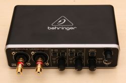
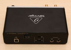
I decided to share a problem that I encountered when I became the owner of the Behringer UMC202HD rev.1.12 card, and describe the way I solved it.
Maybe some of you will need it.
First things first.
Back in the day, looking for a card / interface for audio measurement, and on a budget, I decided to purchase the inexpensive Behringer UMC202HD. Then I took it for granted that since it is compatible with the 192kHz / 24 bit technology, it must have satisfactory parameters.
Unfortunately, the reality turned out to be completely different. The very first test of the card with RightMark Audio Analyzer showed its weakness. The test results showed that it was not suitable for the purpose for which I purchased it. Amazed by this fact, browsing through various entries about it on the web, I found, among other things, a certain comparative test of several different cards, which unfortunately confirmed my disappointment with this Behringer:
https://www.infomusic.pl/test/46209,test-inte...asy-audio-behringer-focusrite-presonus-tascam It must be admitted, as it seems to have been mentioned in those tests, that with this card, each minimal change in the position of the input regulators results in a significant change in the obtained results.
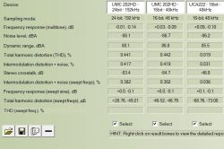
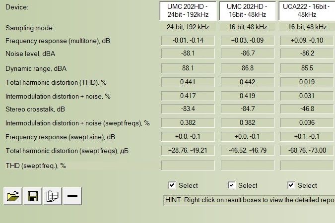
Here are my tests of this card, compared to the much older, cheaper and simpler UCA222 with PCM2902 on board.
At that time, I even thought of withdrawing from the purchase contract and returning it to the seller. However, I decided that I would not give up and I would find and eliminate the cause of the weakness of this card. After a short "fun" I came to the conclusion that its biggest weakness are the input amplifiers (MIDAS, which was mentioned in advertisements as one of the advantages of this card). As an interesting fact, the tests reveal that the MIDAS input amplifiers generate a large level of the second harmonic (generally even). Perhaps the creators wanted to give them a tube sound.
To find out about the aforementioned weakness of these amplifiers, it is enough to connect the card to the USB connector of the computer, connect headphones to it, but do not connect anything to its inputs. Then turn on the Monitor functions and increase the settings of the input controls. You can hear how "beautiful" it generates large noises, which are immediately silenced after turning off the Monitor function.
There was one conclusion - you have to omit the input amplifiers completely.
(To simplify the process of working out the card, I sent an e-mail to the Polish distributor with a request to provide a part of the schematic containing the input amplifiers, unfortunately it remained unanswered.)
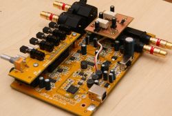
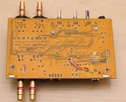
So I rolled the card (interestingly, the card was built on systems with quite good parameters), looked, "figured out" the layout a bit, thought and figured it out.
I found a very simple way to bypass the entire input amplifiers and feed the signal directly from the inputs to the signal symmetrization circuits (implemented on IC8-AD8694) for the IC7-CS4272 converter. Such a solution could be called a direct line input. It had the effect I needed. In this way, I obtained a card with parameters suitable for using it to perform audio measurements.
In order not to lose the factory capabilities of the card, which may be useful for other purposes, I designed a simple module that allows you to switch the card's functionality. Of course, between the factory and the new modified, with a shortened entry track.
Below I will describe how to modify the card, but first a few important notes on this topic.
- Deciding to modify, you lose any warranty.
- Modifications, you carry out on your own responsibility, you are responsible for various effects associated with it, failed activities, etc.
- The modification works when you give the input an unbalanced signal with a jack plug (or an adapter of this type).
- Switching on the modification, completely bypasses the input amplifiers, no manipulators, no input amplifiers.
- Attention!!! When using the modified mode, giving too high input signal can damage IC8 - AD8694 !!!
Description of the modification
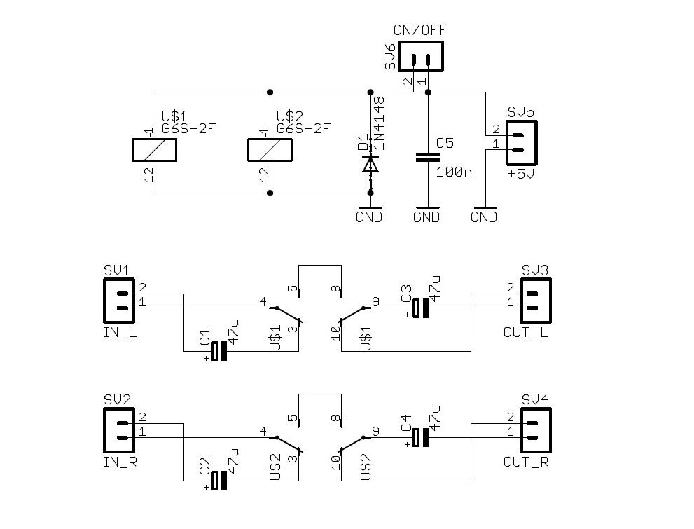
Diagram of an additional module:

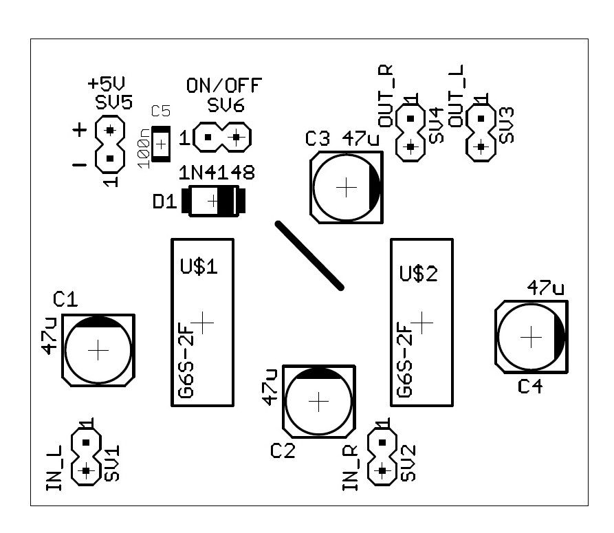
Placement of elements on the board:

Below in the PDF attachment with the mosaic of the tile.
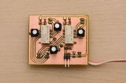
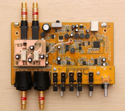
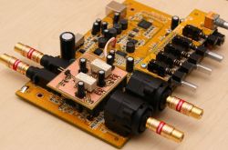
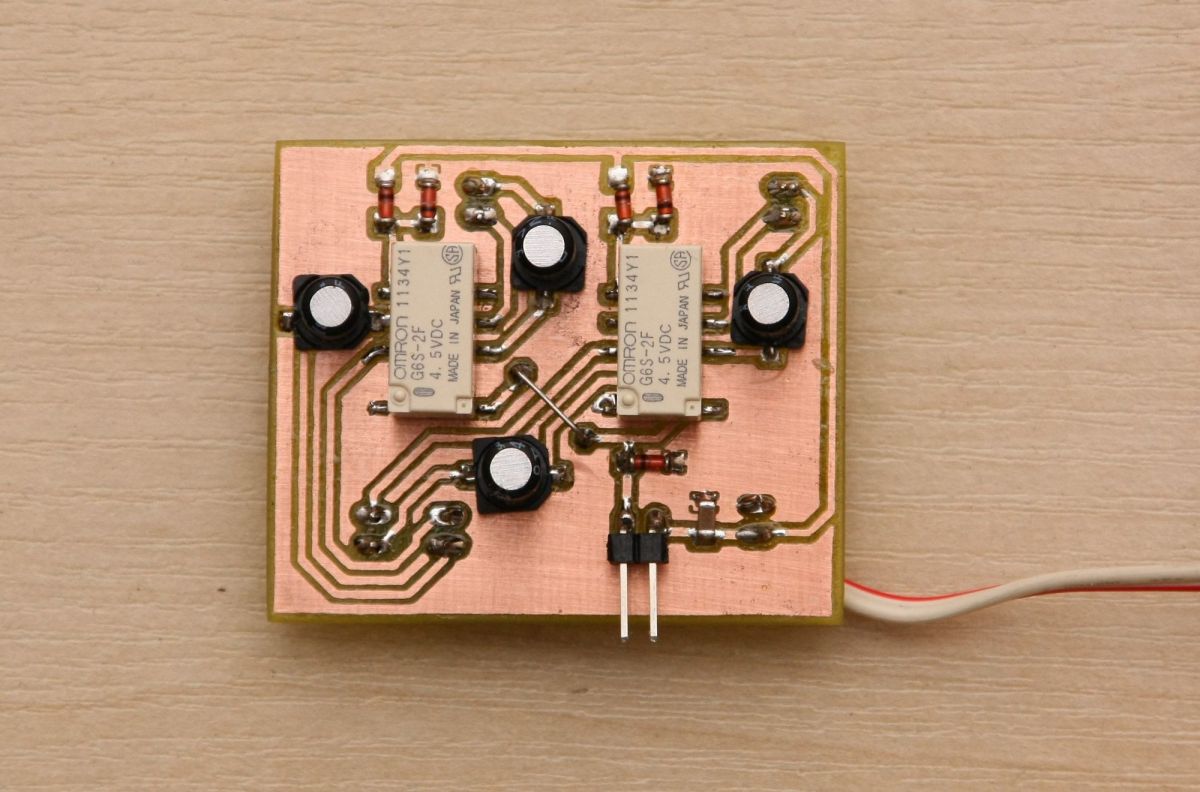
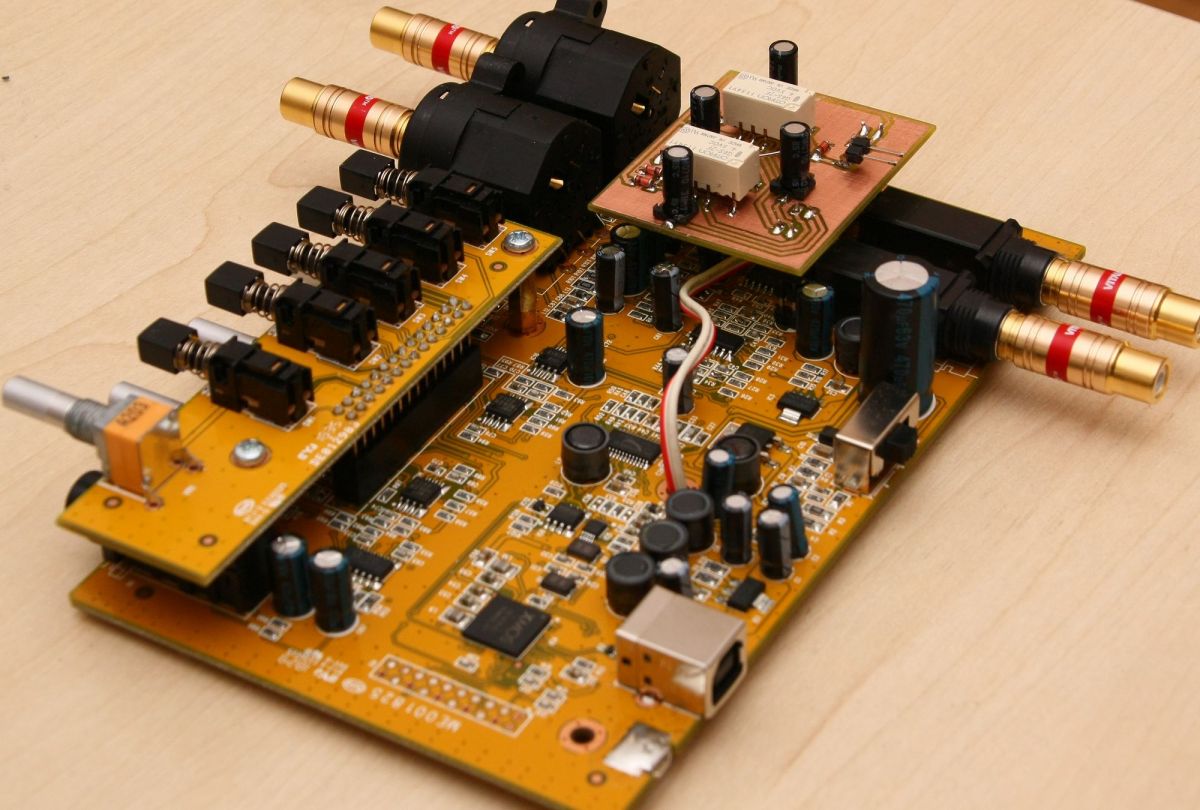
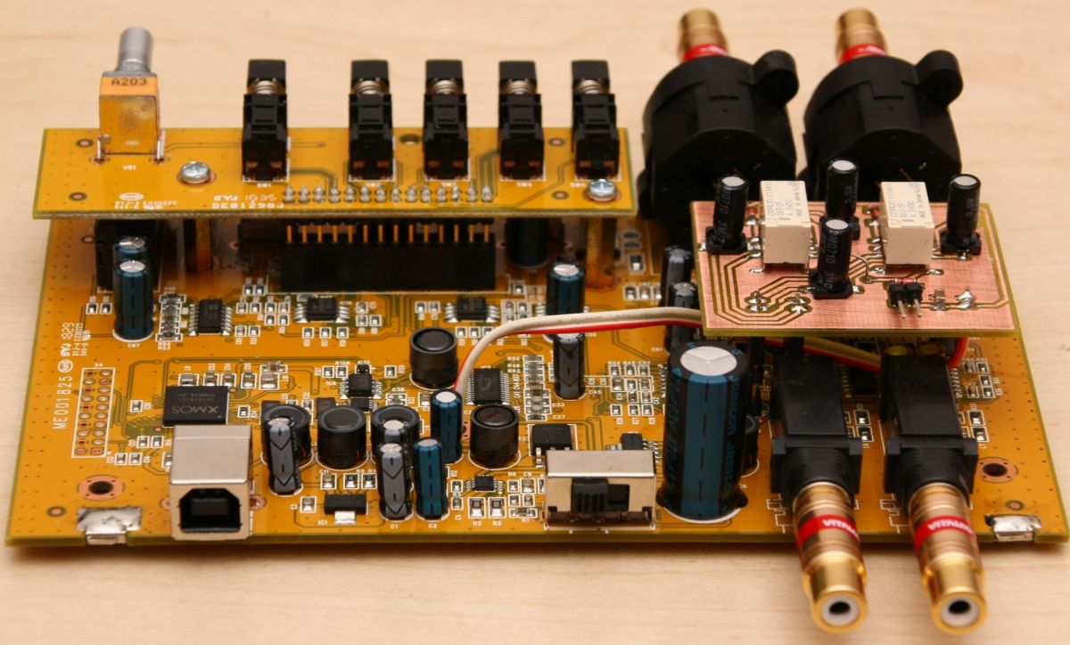
And this is an example of an assembled module.
List of necessary elements:
SMD relay OMRON G6S-2F 5V (or equivalent) - 2 pcs,
SMD capacitor 47uF 16V, preferably bipolar - 4 pcs,
SMD capacitor 1206 100nF - 1 pc,
SMD diode 1N4148 - 1 pc,
Additionally, you will need: a single-section switch, goldpin pins (standard 2.54mm pitch), a piece of a thin two-core cable.
Modification steps:
- Remove the following electrolytic capacitors from the card motherboard: C81, C85, C34, C35
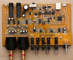
- In place of the capacitors, solder long pins (Gold-pin)
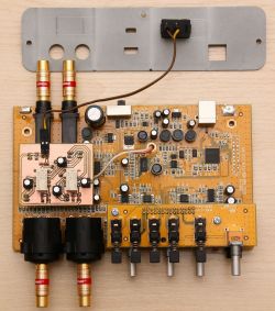
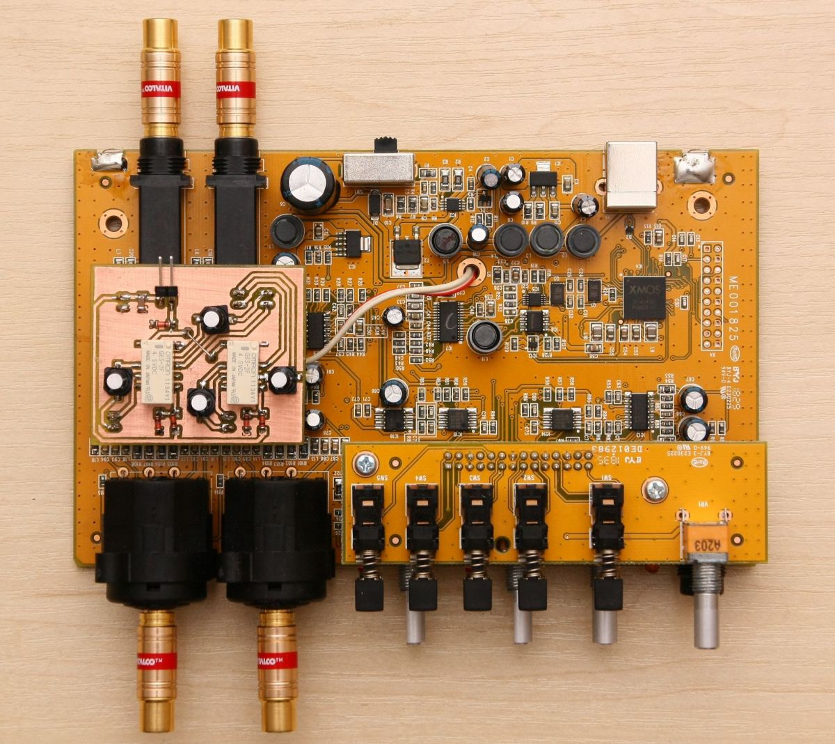
- On the previously installed pins, mount and solder the assembled module.

- Connect the + 5V power supply to the module. I propose, as I did, from the bottom of the board to the pins of the C7 capacitor
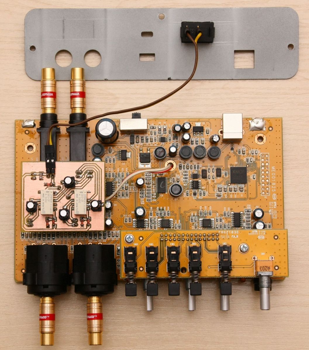
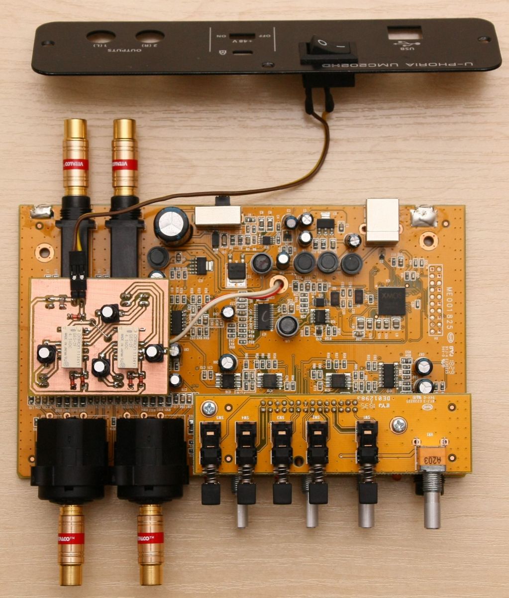
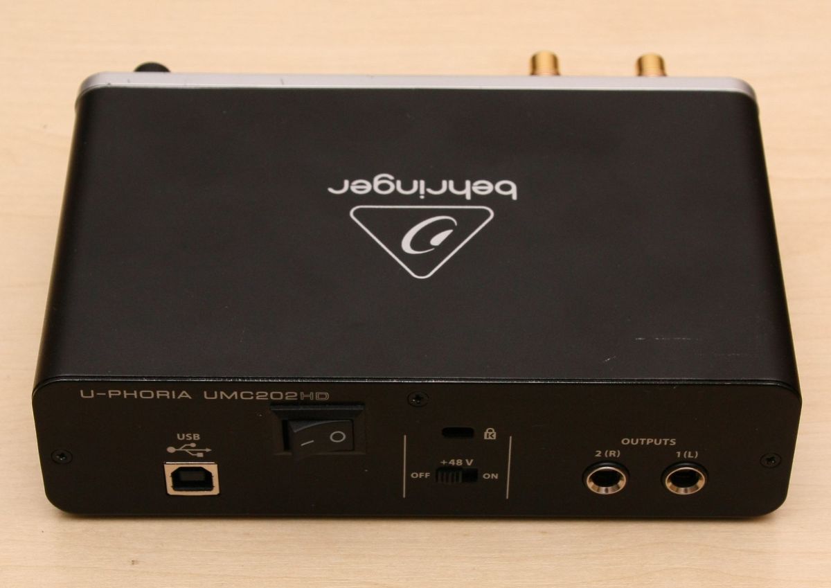
- install the card function switch in the rear housing panel. The ON position enables modification-shortened input path. An example of a photo montage. The switch should be connected to the connector on the added module.
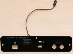

Rear view of the device after modification
Before trying to work, I suggest you check the correctness of all steps!
When the switch on the back wall is turned on, the card has a new functionality (shortened input path), while when it is turned off, it is compatible with the original version.
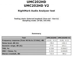
Below, in the appendix, the full test result showing the differences, the green diagram in the appendix marked with the annotation V2, is the result with the attached modification.
And here is a summary, showing the differences in the results of the test.


Comments
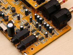
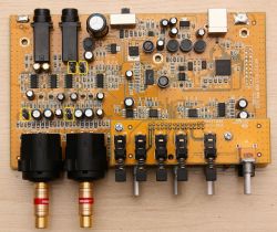
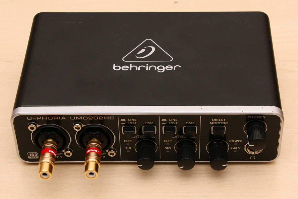
Cool modification, can you take more detailed photos of the PCB? I am curious what operational amplifiers etc. are there. [Read more]
I really like your patent with the removal of the capacitors, adding goldpins in their place and using them at the same time as a signal capture and construction element :) [Read more]
A very clever modification, such a "true bypass" but with that in mind I miss an additional control on the front panel that would remind the user of this fact with its illumination. I have the UMC404HD... [Read more]
Or a limiter that would simply prevent damage - a resistor and two small-signal Shottky diodes are enough. :) [Read more]
We've talked about this before. A great modification worth spending a few free hours because it translates into real value. However, I wonder if every Behringer model has such a disadvantage. If... [Read more]
In my opinion, the chance to significantly improve the parameters and to protect the transmitter inputs was wasted, you had to add amplifiers with good parameters on the board or even replace them on... [Read more]
Integrated circuits (not all, let's say only from the audio path) present in this device - operational amplifiers are mainly quad AD8694 - 4 pcs (input amplifiers - IC9, signal symmetrization for... [Read more]
A very interesting modification! I have the same card, but probably in the 16bit version, I use it with a measuring microphone to adjust / set the dsp in Helix / Match car amplifiers. Tomorrow I will check... [Read more]
Would you be able to measure it with RMAA? [Read more]
I think I can do it. I have to find some time on the weekend and it can be done. Unless it's very difficult ... I'll try. [Read more]
I know that maybe dig a little, but have you not thought about replacing the operational amplifiers in the input circuit? Maybe some minor fixes improved and reduced the noise of this interface. [Read more]
I think that minor corrections (but in this case too little) would not significantly improve the situation, or at least not as much as I needed. Which operational amplifiers would you recommend, my friend? ... [Read more]
This fact is not the best but also not the worst, maybe the gain is too high? I have a Tascam DR-40X recorder and it also hums a bit when it is at high gain. for comparison, the test results for the... [Read more]
I did not work out the input amplifiers of this card in detail (because it was a waste of time), but I have the impression that the input sensitivity switches work in such a way that higher signals are... [Read more]
This is why I am asking because it is difficult to find such a cheap audio interface, if it changed it a bit, it would be the most profitable :D Maybe he will come to me on Monday, so I will sit and see... [Read more]
SSM2019 have min. supply voltage - symmetrical 5V, so there will be a problem, because only unbalanced + 5V cards on board. And let me remind you that in my solution: So it completely bypasses their... [Read more]
I use microphones quite often so the noise from this input is important to me. The fewer the better :) Symmetrical power supply is not a problem, now there are plenty of 5V converters> symmetrical 12V,... [Read more]
The topic is quite old, but there has been some update to my modification that I would like to share. Maybe someone else will find it useful. The first version of the modification unfortunately had... [Read more]
Hello, useful topic for me. I have two cards including one burnt out. I would love to rework it according to your idea but need advice. I have applied too high a voltage to the line inputs and the card... [Read more]