Opens and documents the interior of two Unitra Ania R612 portable radios, rescued from e-waste and shown with boards, wiring, speaker, antenna, and service manual excerpts.
The teardown highlights a ferrite antenna, Tonsil GD8/1/2 1W 8Ω speaker, UL1219 and UL1497 ICs, plus a separate bridge-rectifier and fuse board.
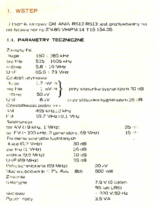
The receiver uses the OIRT UKF band, 65.5–74 MHz, and runs from 5 R6 batteries at 7.5V or mains through a transformer marked UNITRA ZATRA TS2/22.
After re-soldering a loose electrolytic capacitor and repairing a cracked ferrite-antenna PCB trace, both radios produced their first sound, though reception remains rough and untuned.
Generated by the language model.
.
Hello my dears .
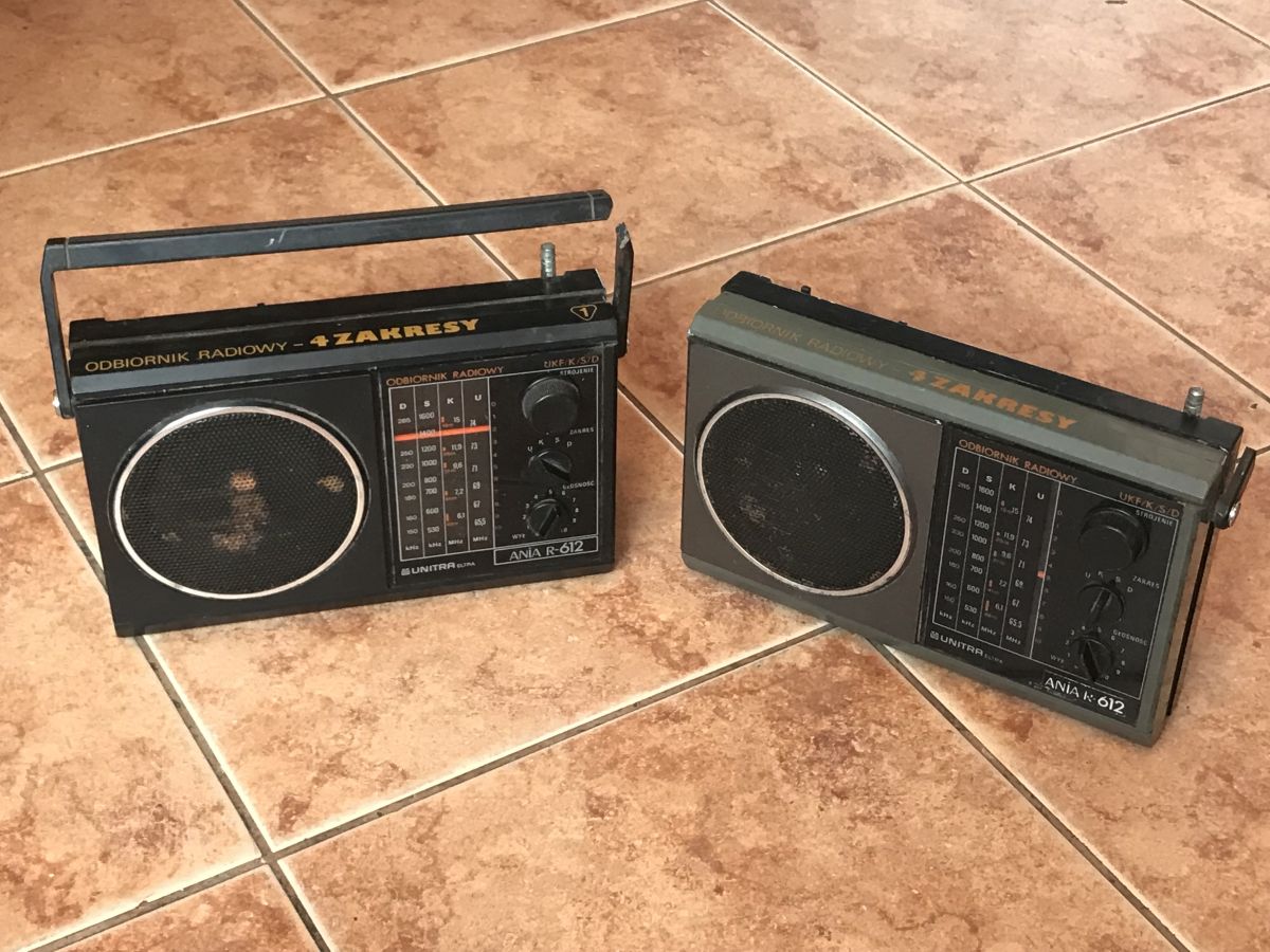
I recently got my hands on two Ania R612 radio receivers made by Unitra. Here I will show their interior, give clear pictures of the boards with commentary and post the full manual and catalogue notes of the components that are inside.
Introduction and teardown .
I rescued both radios from electro-waste, someone just wanted to throw them away. I know they don't have much value, but I have a lot of respect for Polish technical thought and old Unitra equipment, so I couldn't leave them like that, even though they were in quite poor condition - no antenna, broken handle, dirty casing:
.
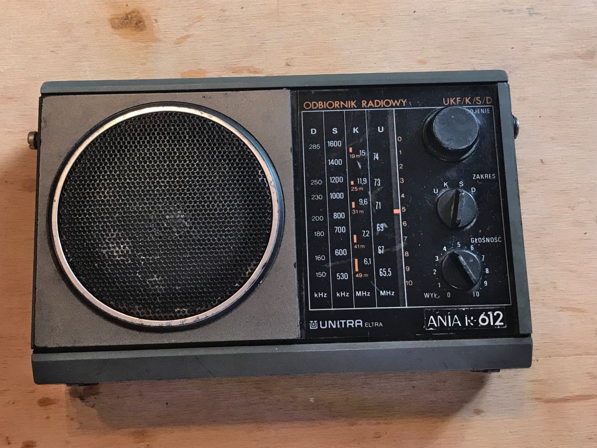
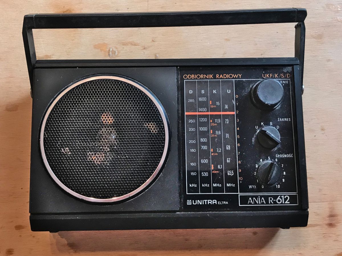
The radio on the front has three knobs:
- range selection (UKF/K/S/D)
- tuning
- volume (with switch)
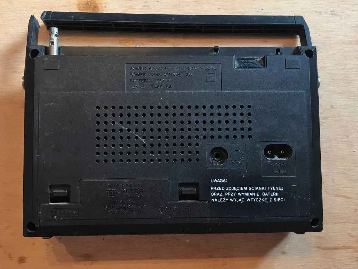
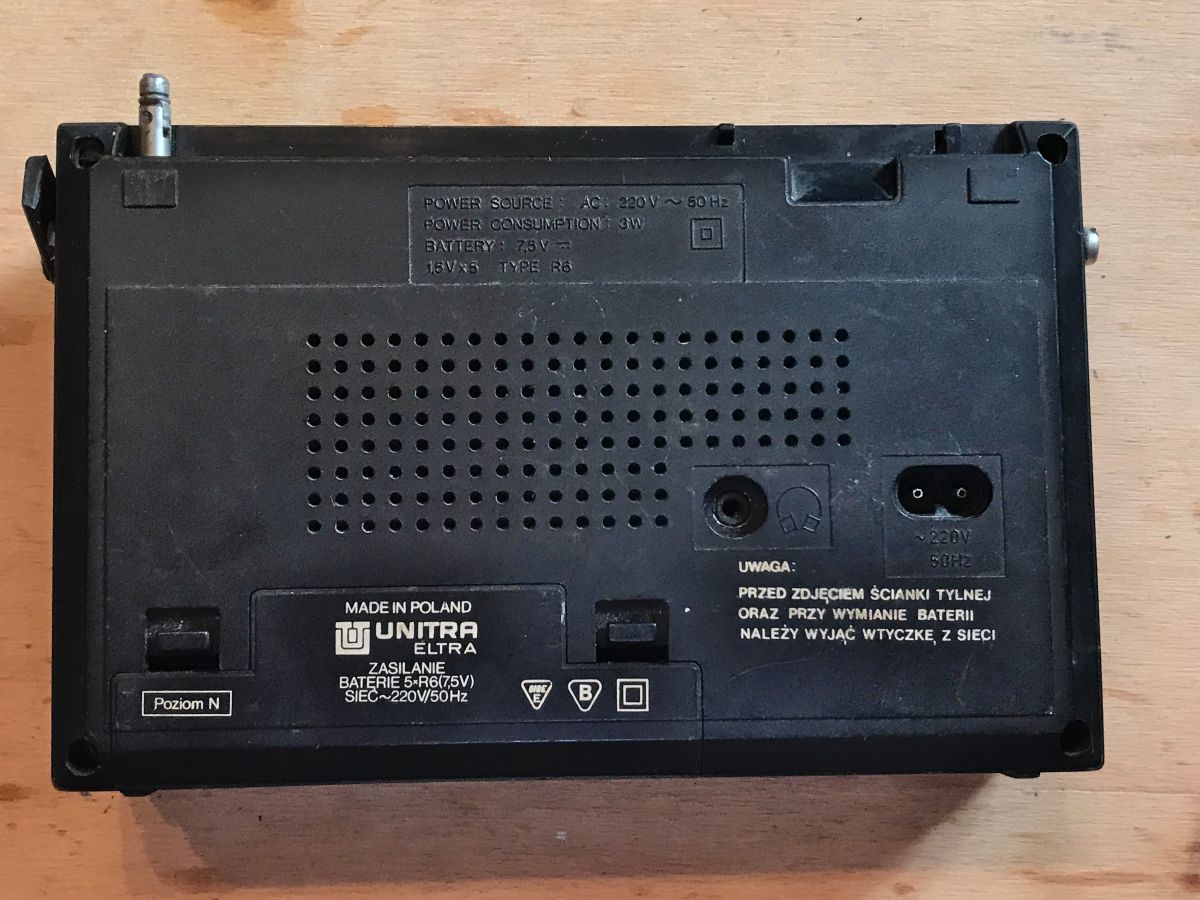
The rear presents itself as follows:
.
On the back we have:
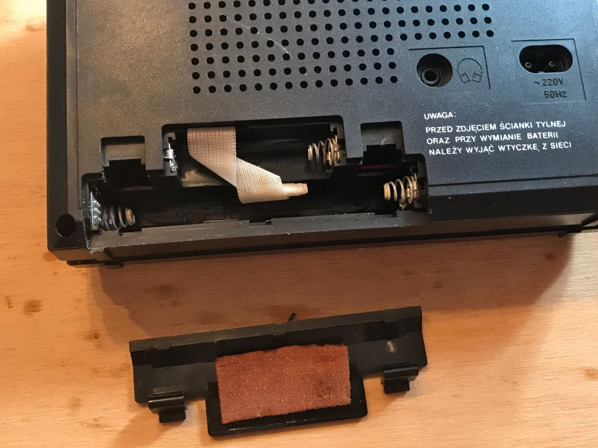
- space for batteries (5 R6, 7.5V)
- connector for 230V power cable
- headphone connector
There is also the information Power Consumption: 3W.
Fortunately, there were no batteries inside, although the condition of the contacts on one of the radios indicated that they had probably spilled out in there before.
.
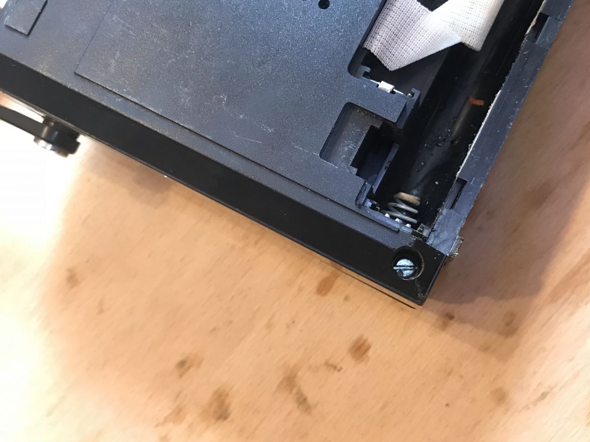
The case is held on by four flathead screws:
.
Care must be taken when opening - the cable from the antenna prevents the cover from being removed initially:
.
Fortunately the antenna connection can be removed:
.
Then the two parts of the housing are already held on by just two wires from the power supply:
.
.
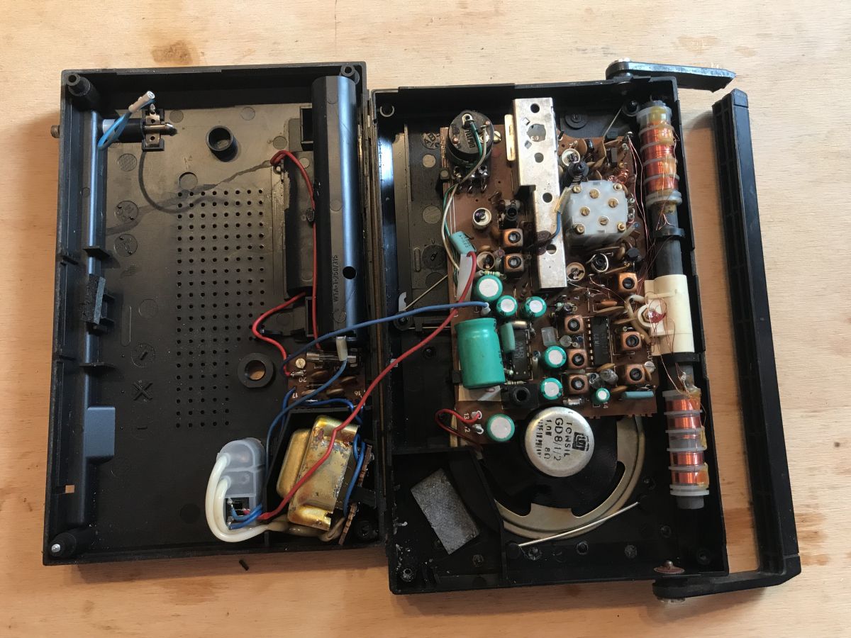
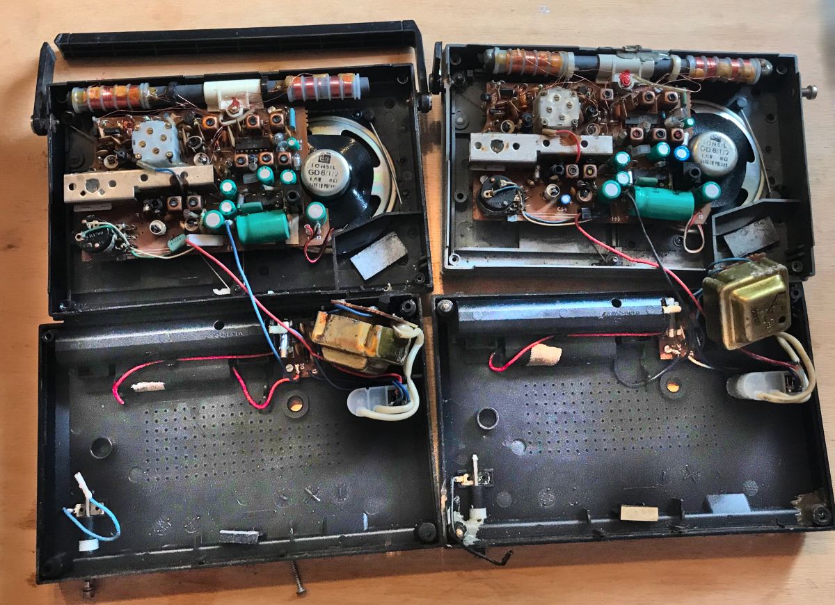
Both radios open in one photo:
.
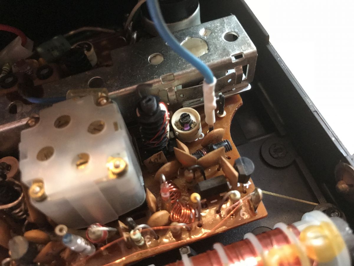
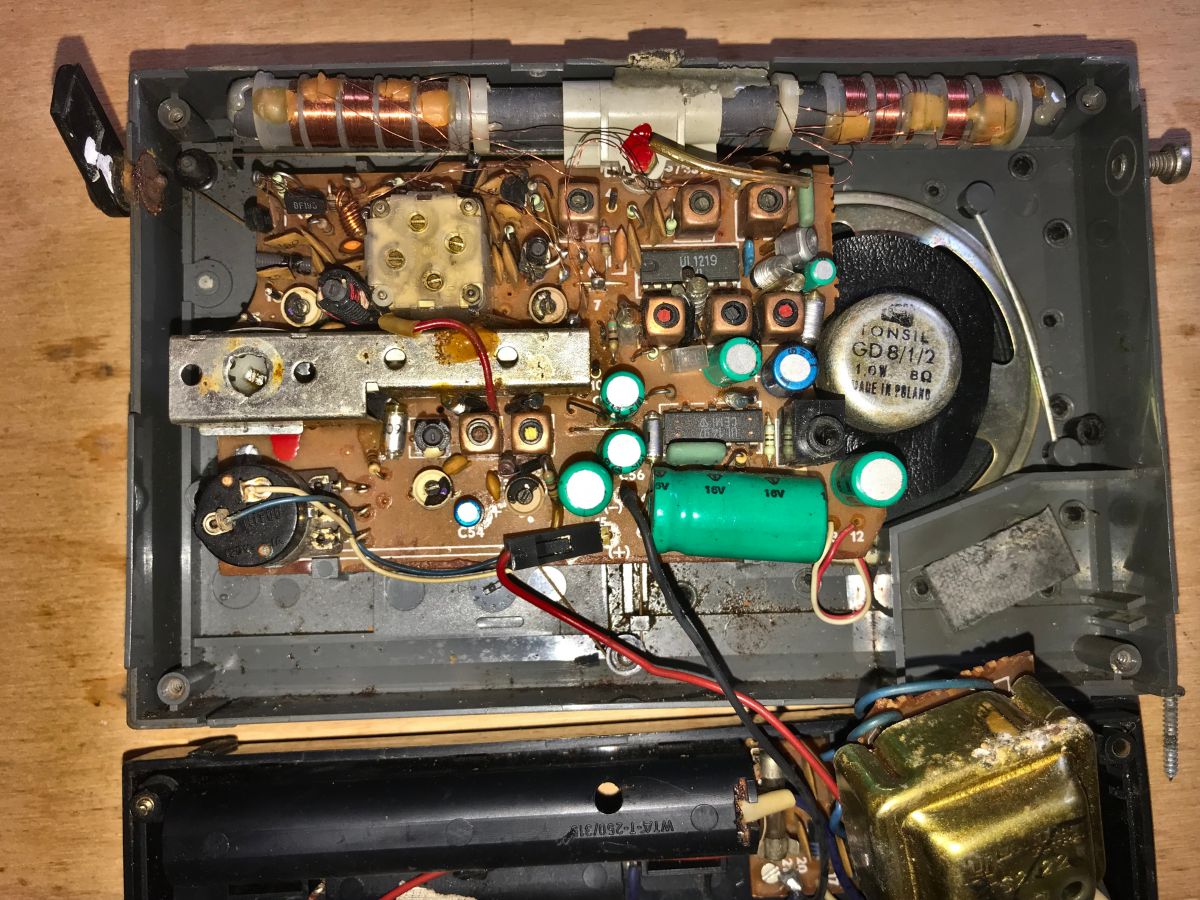
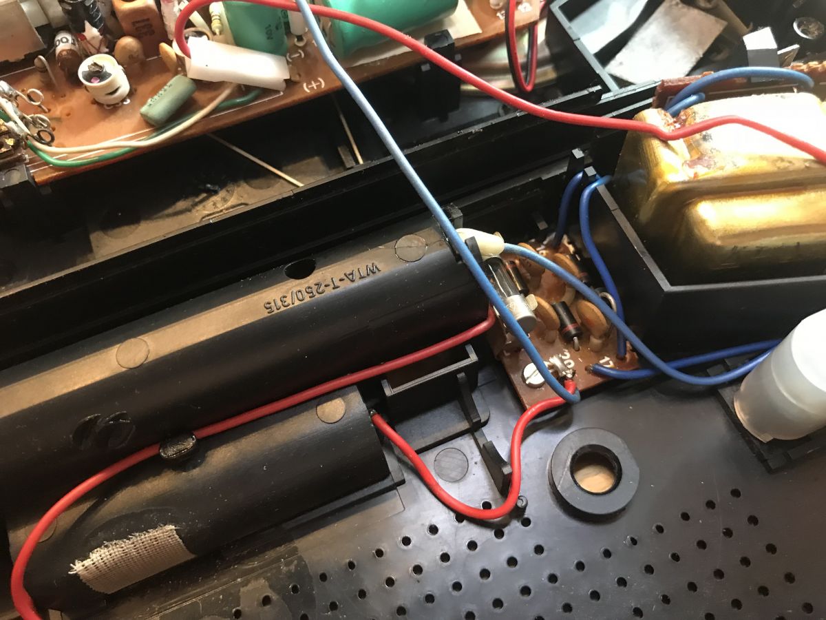
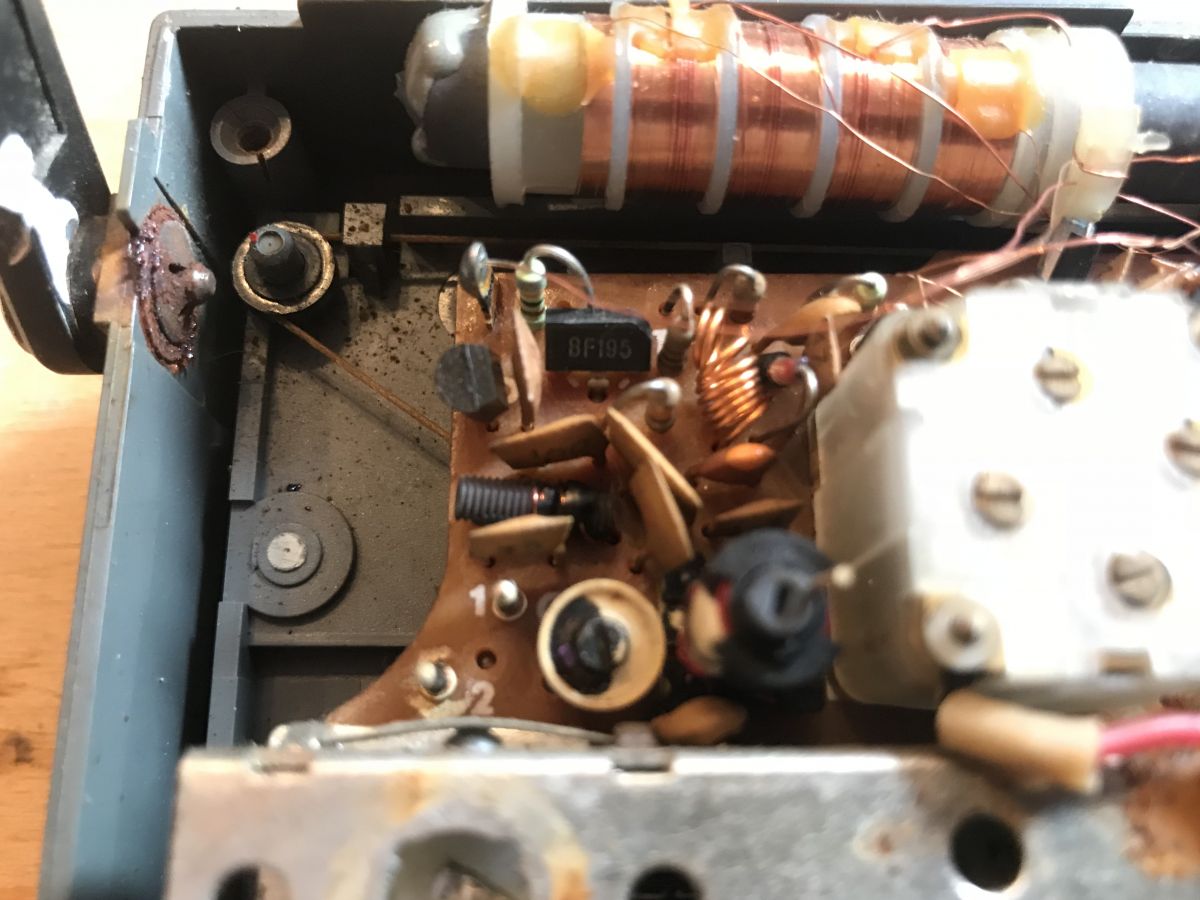
Inside, what immediately catches the eye is a large ferrite antenna, typical of such older receivers. Next to it we have a 1W 8Ω Tonsil GD8/1/2 loudspeaker. Directly on the main board is the jack connector from the headphones, and there is also another characteristic element, the adjustable capacitor (actually there are several trimmers inside it, not one).
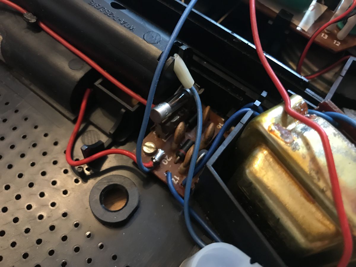
On the rear cover side is a separate board with a fuse and Greatz bridge. What was striking to me here was that the fuse was out of place - the radio must have fallen to someone.
.
.
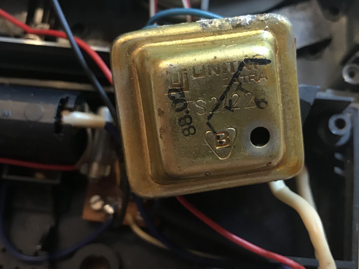
The transformer can be removed, it is only held on by a plastic clip.
Signed is:
UNITRA ZATRA
TS2/22 .
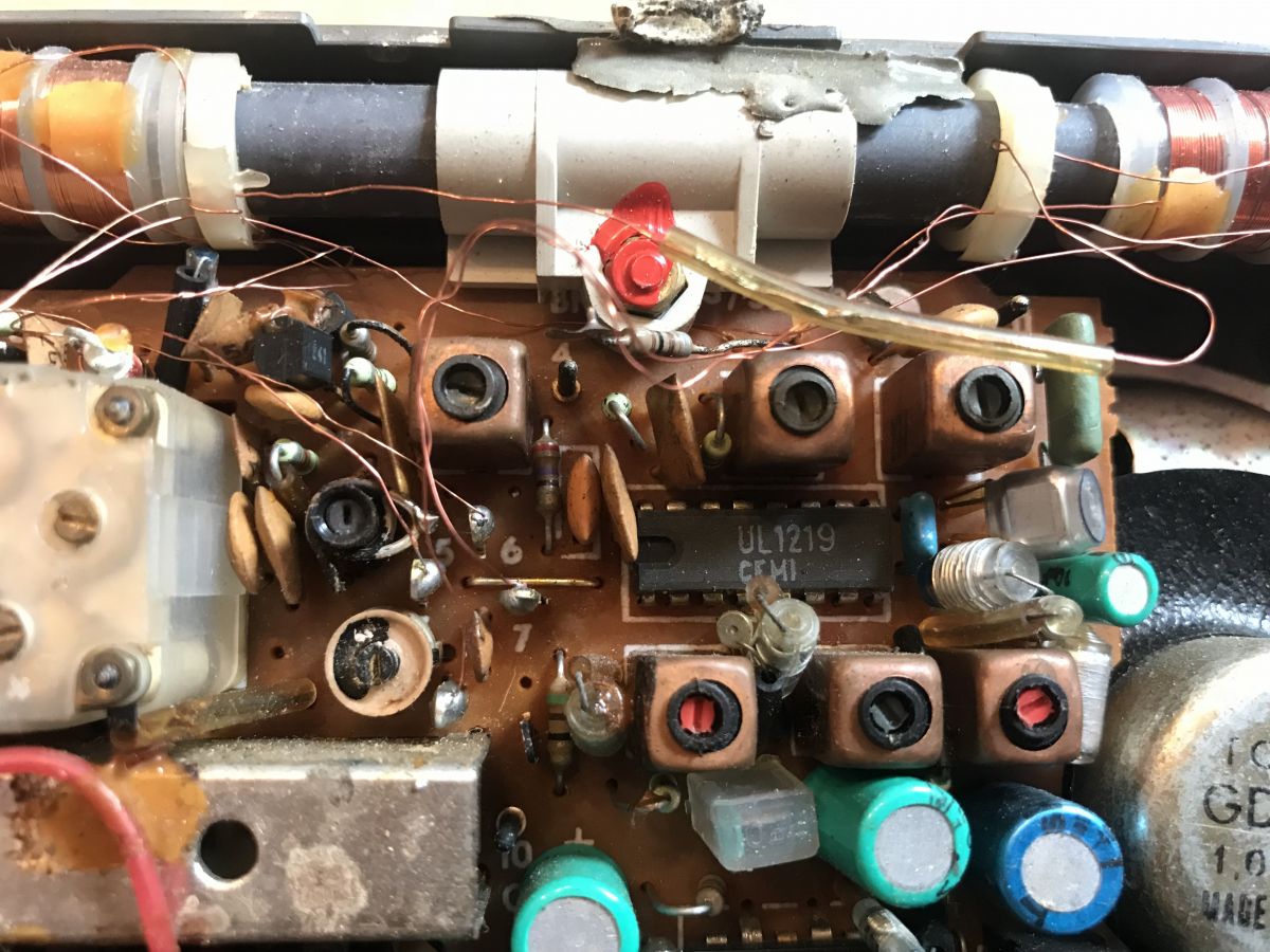
The main PCB has on board two ICs.
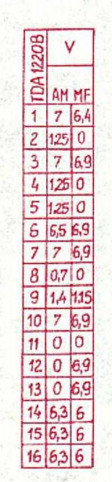
UL1219 (equivalent to TDA1220B, heterodyne IC and A.M. mixer AM/FM intermediate frequency amplifier, AM/FM detector):
.
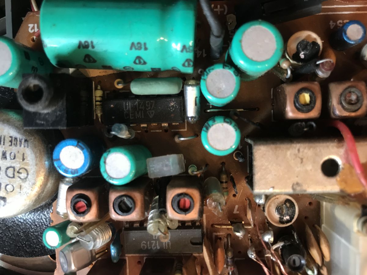
UL1497 (low-frequency amplifier; a loudspeaker is connected to it):
.
There are also transistors; BF195:
.
Diode 811 (BAP-811):
.
By the way, I noticed that one of the electrolytic capacitors no longer holds on to its solders (as I mentioned earlier, the radio must have fallen to someone):
.
I later corrected these solders.
In order to remove the main board from the housing, you have to unscrew the screws holding it in place and then additionally remove the three knobs from the front of the radio:
.
.
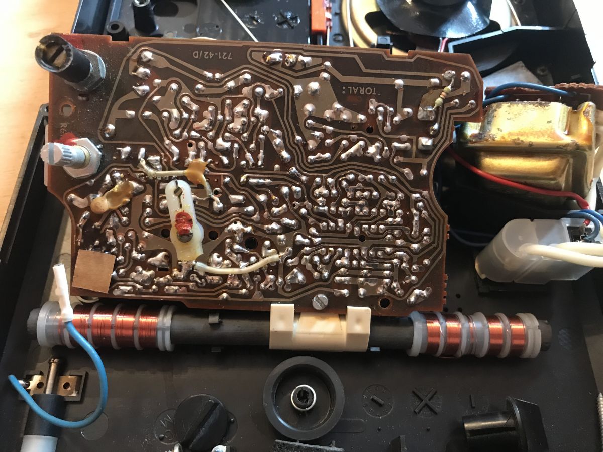
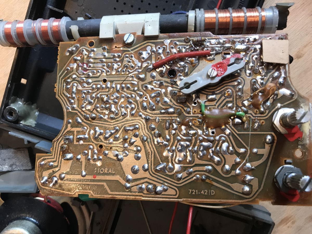
After that, you can already admire its paths from below:
.
The paths on this board in no way resemble what we have in the devices now - they were probably run by hand, although who knows? Maybe someone reading this knows more about how these PCBs were made and will share the details.
.
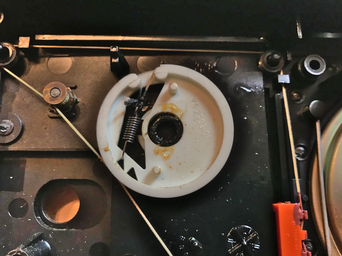
Also visible here is the tuning mechanism with the cable:
.
.
Here, remember not to move the tuning after removing the electronics board, as the tabs on the plastic tuning piece must match the trimmer when fitting the radio back together.
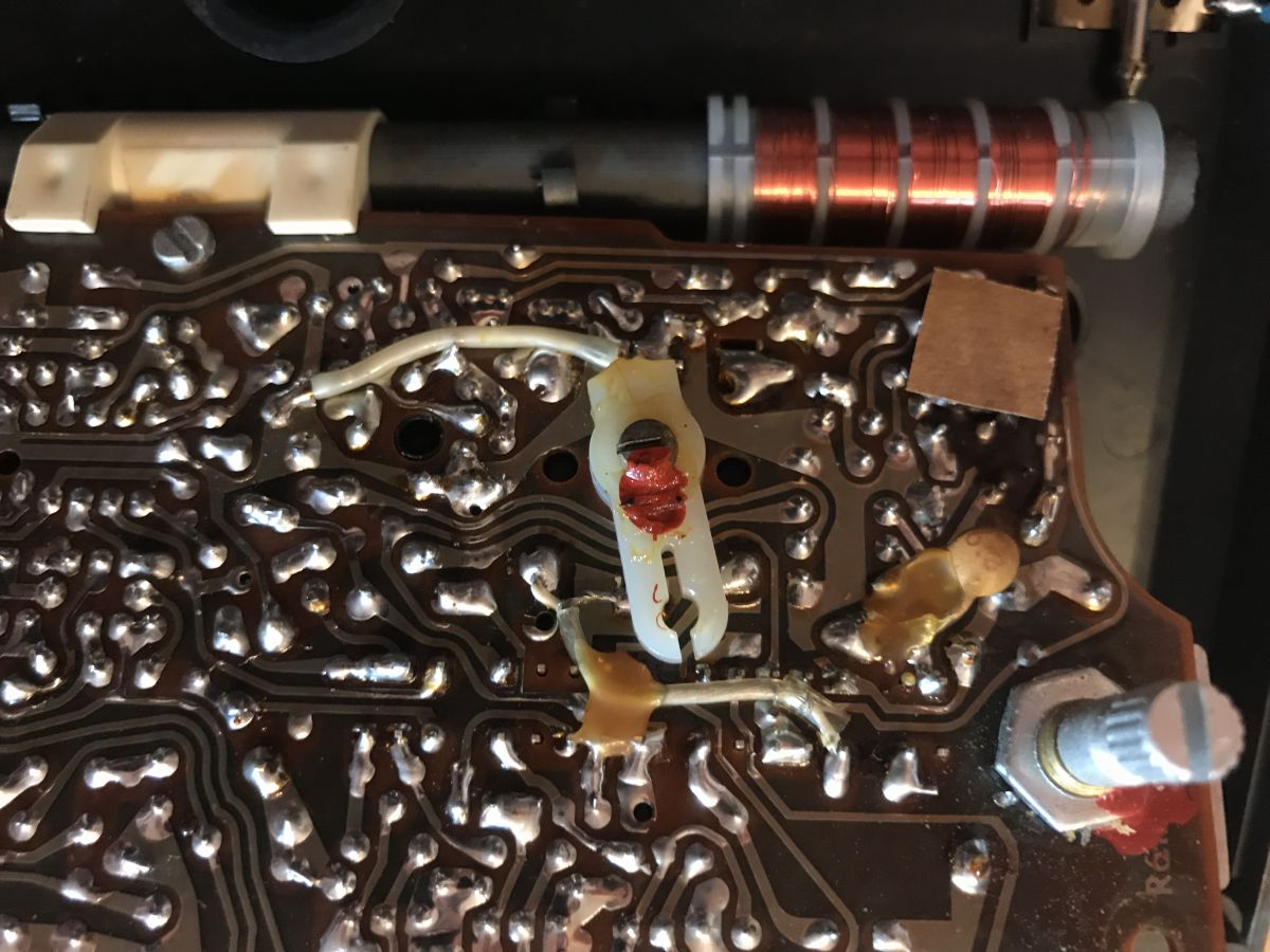
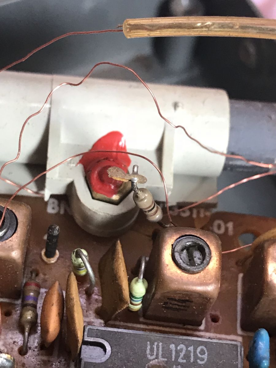
One of the radios had a section of the ferrite antenna PCB broken off:
.
.
As a result of this, one path with a resistor was also damaged:
.
I immediately glued the PCB together and repaired the path with a tin bridge:
.
First voice .
This was not the purpose of this article, but after the minor adjustments described in the previous paragraph I managed to get the first voice out of both radios.
The result in the videos:
.
.
You can hear the cringing and from a distance you can see that there is still a lot of work left to restore them to good condition, but I'll talk about that in another topic.
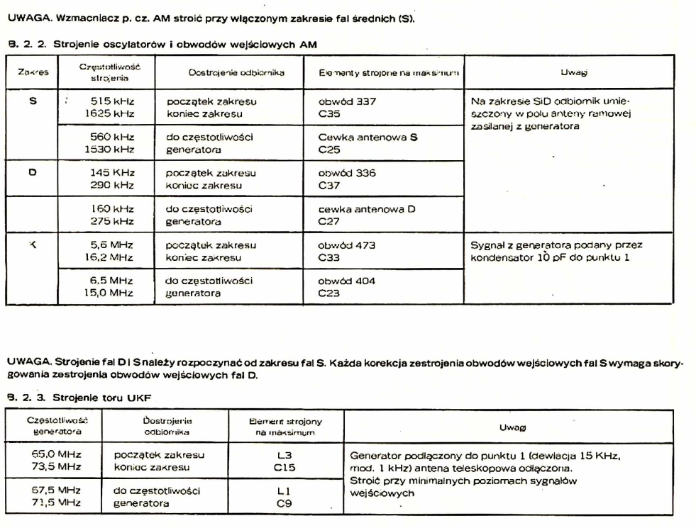
Need to tune the receiver .
It is worth noting here that the Annie R612 receives on the UKF range 65.5 - 74MHz (the OIRT band; the so-called "lower band"), and these days stations transmit on the CCIR range (87.5 - 108MHz). The 65.5-74MHz band was used in Poland until 31 December 1999, so it's unlikely we'll be able to listen to much UKF on it without some tuning. However, this is not the subject of this post, and I am yet to undertake the tuning, so I will only write about it in a little while.
Manual from Unitra .
Almost as impressive as the radio itself is its manual - downloadable here in the appendix:
Ania_R612-..613.pdf (14.16 MB)You must be logged in to download this attachment. .
The manual includes the date - 1986 - which is over 30 years ago.
.
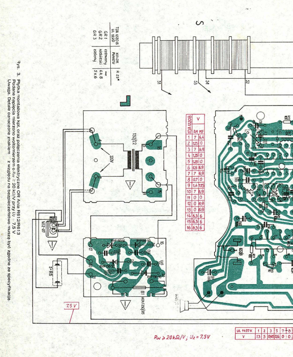
The manual has what is called an 'exploded view' - a breakdown of all the radio components/details:
.
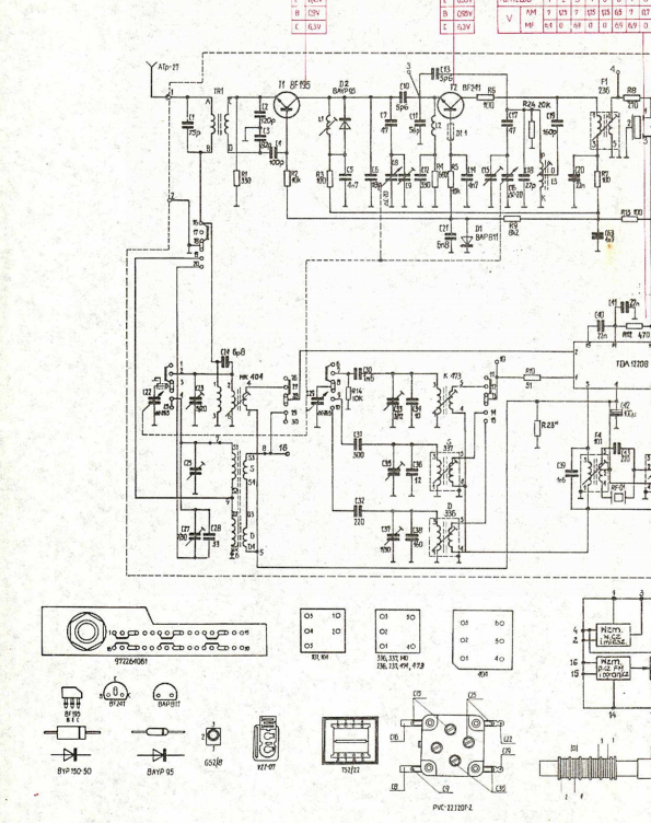
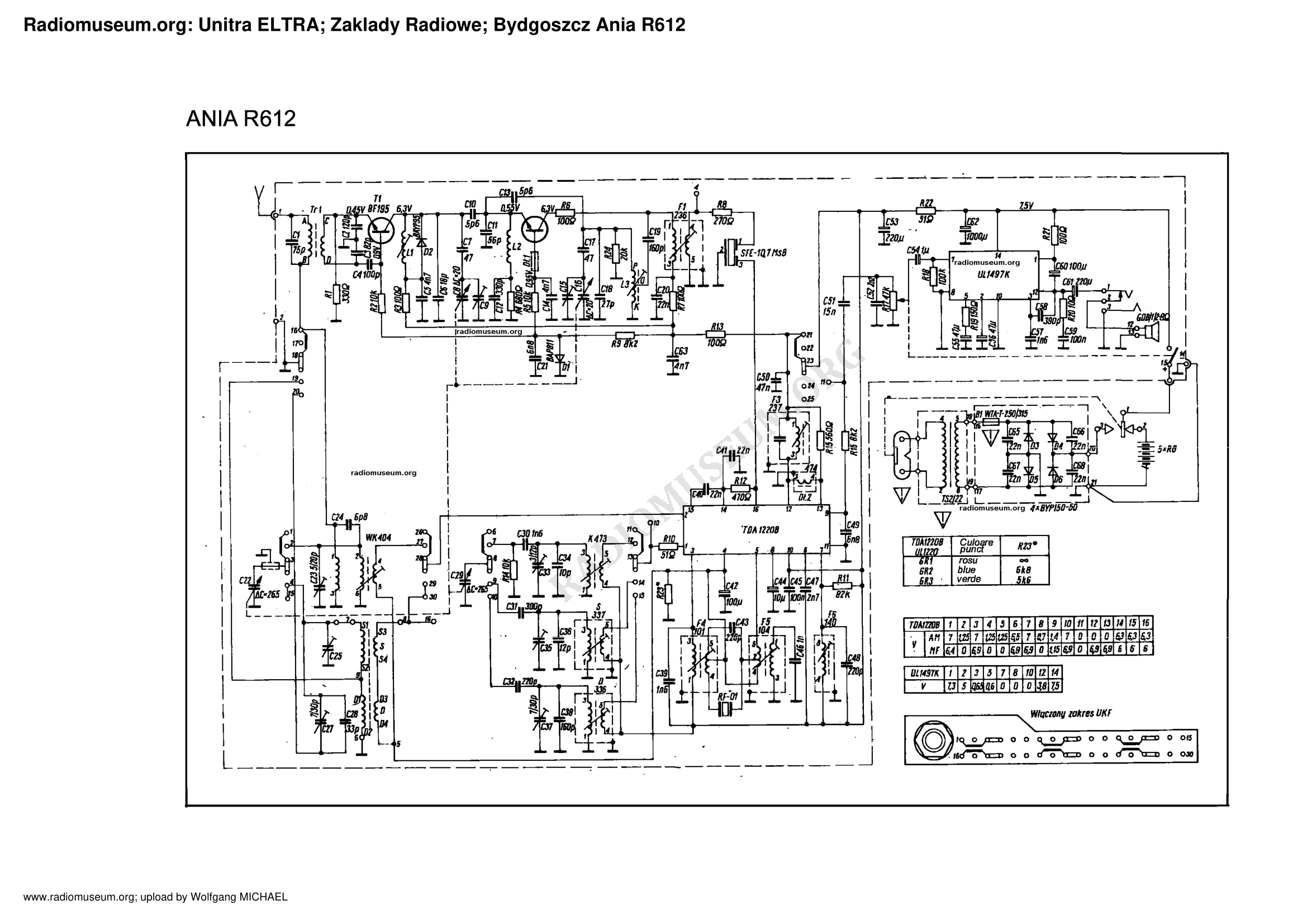
In the manual there is, of course, a schematic diagram - but both the idea version and the with PCB:
.
.
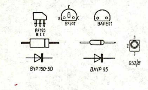
There are even component leads described:
.
Voltages are also given, even those on individual IC pins:
.
Extremely detailed radio reception parameters are available:
.
Details of tuning and associated components are also described:
.
In conclusion, the documentation of the Ania R612 receiver from Unitra in no way resembles the documentation of the equipment produced nowadays. It is very detailed and one gets the impression that it is written with the intention of making it easier to service and repair the receiver, so that it can work for a really long time.
Attachments .
I enclose here the catalogue notes of the components found in this receiver.
BAYP95:
BAYP95_CEM...ota.pl.pdf (130.73 kB)You must be logged in to download this attachment. .
BF194/BF195:
BF194_Va..e.pdf (54.35 kB)You must be logged in to download this attachment. .
BF240:
BF240 - B..41.pdf (63.61 kB)You must be logged in to download this attachment. TDA1220B (counterpart UL1219):
TDA122..pdf (418.48 kB)You must be logged in to download this attachment. .
UL1497/UL1490N:
UL1490N_U..ra.pdf (604.14 kB)You must be logged in to download this attachment. .
BAP811:
BAP811_CEM...ota.pl.pdf (1.24 MB)You must be logged in to download this attachment. .
Radio diagram itself:
Summary .
In this topic I have essentially limited myself to depicting the interior of the Ania R612 receiver. I also intend to get into its restoration and tuning in the future, but that's in another topic.
In the meantime I invite you to comment - do you have any memories or anecdotes related to old Polish radios? Maybe some technical details? Or maybe someone will provide pictures of the inside of their receivers (hopefully in better condition than mine)?
About Author
p.kaczmarek2 wrote 14620 posts with
rating 12636 , helped 655 times.
Been with us since 2014 year.
It is difficult to say how the PCB of this copy was created. In those days it was possible to reflect the design on a die, for example, or to trace it with a stencil. Later such a PCB would undergo a visual... [Read more]
katakrowa
15 Jun 2020 16:25
I've never been a big fan of communist-era electronics, although I have most fond memories of them. Even though the quality sometimes differed from the western competition, I have to admit that for the... [Read more]
jaskowisnia
15 Jun 2020 21:24
.
Exactly, I started by rummaging around with this type of equipment back in the 1970s. Back then, as a rule, the demand was greater, or definitely greater for the more interesting equipment than the... [Read more]
Olkus
15 Jun 2020 21:35
Hi. My experience with the tiles is that the tracks peel off. [Read more]
398216 Usunięty
15 Jun 2020 22:37
Tin itself is not very mechanically robust, and already once cracked the laminate will also not reach its original strength after gluing. I would suggest reinforcing the solder with silver or a not too... [Read more]
pawelr98
15 Jun 2020 22:56
I played with exactly the same radio as the author of the topic shows as a kid.
I rescued a Dior DSP-301 "Duet" from the dumpster and took and tuned a "Tambourine" from the lot.
"Duet" got a new... [Read more]
rb401
16 Jun 2020 04:52
As much as possible was drawn by hand. The whole world used to do it that way, because the origins of PCBs are ancient times. Only the essence of the method was that the draughtsman made a drawing on a... [Read more]
abart64
16 Jun 2020 05:47
On YT I once watched a short report from Toral, an excerpt from the Polish Newsreel I think. Unfortunately I can't find it again. It was where a lady was plotting the paths on a film board. The drawing... [Read more]
cirrostrato
16 Jun 2020 08:18
My first job after graduation, year 1977, some prototype circuit was previously launched in the design office (unit production, few pieces per year) but the PCB required four layers (PCB for digital memory,... [Read more]
According to the linked Radiomuseum website, this radio was designed in the GDR by RFT. Unitra produced it for the domestic market and for export. I don't know whether Unitra bought the licence or some... [Read more]
kris8888
16 Jun 2020 12:22
.
Not the same, as this East German radio was already in a stereo version with two power amplifiers on board. Stereo listening on headphones or perhaps by connecting an additional external speaker.
So... [Read more]
^ToM^
16 Jun 2020 14:00
This East German radio was actually co-operatively manufactured in our country for their market. This is evidenced by the markings on the schematic in the form of ULxxxx series chips. [Read more]
ml
16 Jun 2020 14:08
Eeee there.... The SR30 is our Annie R614
https://www.oldradio.pl/karta.php?numer=151 [Read more]
^ToM^
16 Jun 2020 14:31
By all means, this option is also possible. In any case, two identical designs were not created by accident and only one design that was replicated by others within the block of socialist technical thought!
"Das... [Read more]
Q1P
16 Jun 2020 19:45
.
Almost certain that this is an Eltra product. The instruction manual in which no information has been translated on the schematic can testify to this. [Read more]
Jacekser
16 Jun 2020 21:40
Phenol-formaldehyde laminate. Plates made by screen printing. Cheapest it was and quite mechanically poor (brittle). Tracks came off easily when overheated. [Read more]
Olkus
16 Jun 2020 22:14
@Jacekser Exactly right. I guess that's the only thing I don't like about those receivers from that era. [Read more]
^ToM^
17 Jun 2020 07:52
If you repair with a transformer they come off. If you use a soldering iron this problem does not occur. :) [Read more]
FAQ
TL;DR: Ania R612, 1986 Polish portable, draws 3 W and still plays; “engineering … higher level” [Elektroda, katakrowa, post #18760833] Collectors retune its 65.5-74 MHz OIRT FM to 87.5-108 MHz.
Why it matters: Restoring or modding the R612 keeps vintage Polish engineering alive while adding modern FM reception.
UL1219 handles AM/FM mixing and detection; UL1497 drives the 1 W 8 Ω speaker. Front-end transistors are BF195, BF194, and mixer diodes BAP-811/BAYP95 [Elektroda, p.kaczmarek2, post #18760684]
Why do copper tracks lift so easily?
The board is phenol-formaldehyde paper laminate. Its adhesive softens above 180 °C; transformer solder guns exceed 350 °C, causing lifting [Elektroda, Jacekser, post #18763538] "Use a 30 W iron, not a gun" advises user ^ToM^ [Elektroda, 18764080]
How were these PCBs drafted in the 1980s?
Designers hand-taped 2:1 or 4:1 scale artwork on Astralon film using self-adhesive pads and tracks, then reduced it photographically for etching [Elektroda, rb401, post #18761911]
Which export or re-branded versions exist?
Identical chassis sold as Nordmende Essex 1654 (West Germany) and Anja RT-432 (Czechoslovakia). A stereo SR30/Ania R614 variant added a second UL1497 and headphone jack [Elektroda, Q1P, post #18762330]
Is there a stereo upgrade path for the R612?
The PCB lacks space for a second power amp and de-emphasis network, so full stereo is impractical. Use line-out from the detector into an external stereo decoder if desired [OldRadio.pl, 2022].
How does the later Ania 2 / Ania 3 differ?
Those sets drop SW, add full 87.5-108 MHz FM, and replace the discrete front-end with single-chip CXA1119 or TDA1220B modules, cutting component count by ~40 % [Elektroda, ojciec, post #18787735]
 .
.
 .
.
 .
.
 .
.
 .
.
 .
.
 .
.
 .
.
 .
.
 .
.
 .
.
 .
.
 .
.
 .
.
 .
.
 .
.
 .
.
 .
.
 .
.
 .
.
 .
.
 .
.
 .
.
 .
.
 .
.
 .
.
 .
.
 .
.
 .
.
 .
.
 .
.
 .
.
 .
.
 .
.

Comments
It is difficult to say how the PCB of this copy was created. In those days it was possible to reflect the design on a die, for example, or to trace it with a stencil. Later such a PCB would undergo a visual... [Read more]
I've never been a big fan of communist-era electronics, although I have most fond memories of them. Even though the quality sometimes differed from the western competition, I have to admit that for the... [Read more]
. Exactly, I started by rummaging around with this type of equipment back in the 1970s. Back then, as a rule, the demand was greater, or definitely greater for the more interesting equipment than the... [Read more]
Hi. My experience with the tiles is that the tracks peel off. [Read more]
Tin itself is not very mechanically robust, and already once cracked the laminate will also not reach its original strength after gluing. I would suggest reinforcing the solder with silver or a not too... [Read more]
I played with exactly the same radio as the author of the topic shows as a kid. I rescued a Dior DSP-301 "Duet" from the dumpster and took and tuned a "Tambourine" from the lot. "Duet" got a new... [Read more]
As much as possible was drawn by hand. The whole world used to do it that way, because the origins of PCBs are ancient times. Only the essence of the method was that the draughtsman made a drawing on a... [Read more]
On YT I once watched a short report from Toral, an excerpt from the Polish Newsreel I think. Unfortunately I can't find it again. It was where a lady was plotting the paths on a film board. The drawing... [Read more]
My first job after graduation, year 1977, some prototype circuit was previously launched in the design office (unit production, few pieces per year) but the PCB required four layers (PCB for digital memory,... [Read more]
. There is also a diagram. [Read more]
According to the linked Radiomuseum website, this radio was designed in the GDR by RFT. Unitra produced it for the domestic market and for export. I don't know whether Unitra bought the licence or some... [Read more]
. Not the same, as this East German radio was already in a stereo version with two power amplifiers on board. Stereo listening on headphones or perhaps by connecting an additional external speaker. So... [Read more]
This East German radio was actually co-operatively manufactured in our country for their market. This is evidenced by the markings on the schematic in the form of ULxxxx series chips. [Read more]
Eeee there.... The SR30 is our Annie R614 https://www.oldradio.pl/karta.php?numer=151 [Read more]
By all means, this option is also possible. In any case, two identical designs were not created by accident and only one design that was replicated by others within the block of socialist technical thought! "Das... [Read more]
. Almost certain that this is an Eltra product. The instruction manual in which no information has been translated on the schematic can testify to this. [Read more]
Phenol-formaldehyde laminate. Plates made by screen printing. Cheapest it was and quite mechanically poor (brittle). Tracks came off easily when overheated. [Read more]
@Jacekser Exactly right. I guess that's the only thing I don't like about those receivers from that era. [Read more]
If you repair with a transformer they come off. If you use a soldering iron this problem does not occur. :) [Read more]