Hello, inspired by the designs presented on the forum, I decided to build my own amplifier, the project is strongly based on
Mosfet 2x50W amplifier with atTiny driver and remote control the heart of which is a power amplifier copy of the Rotel RA-820.
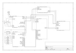
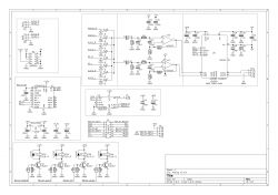
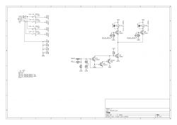
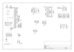
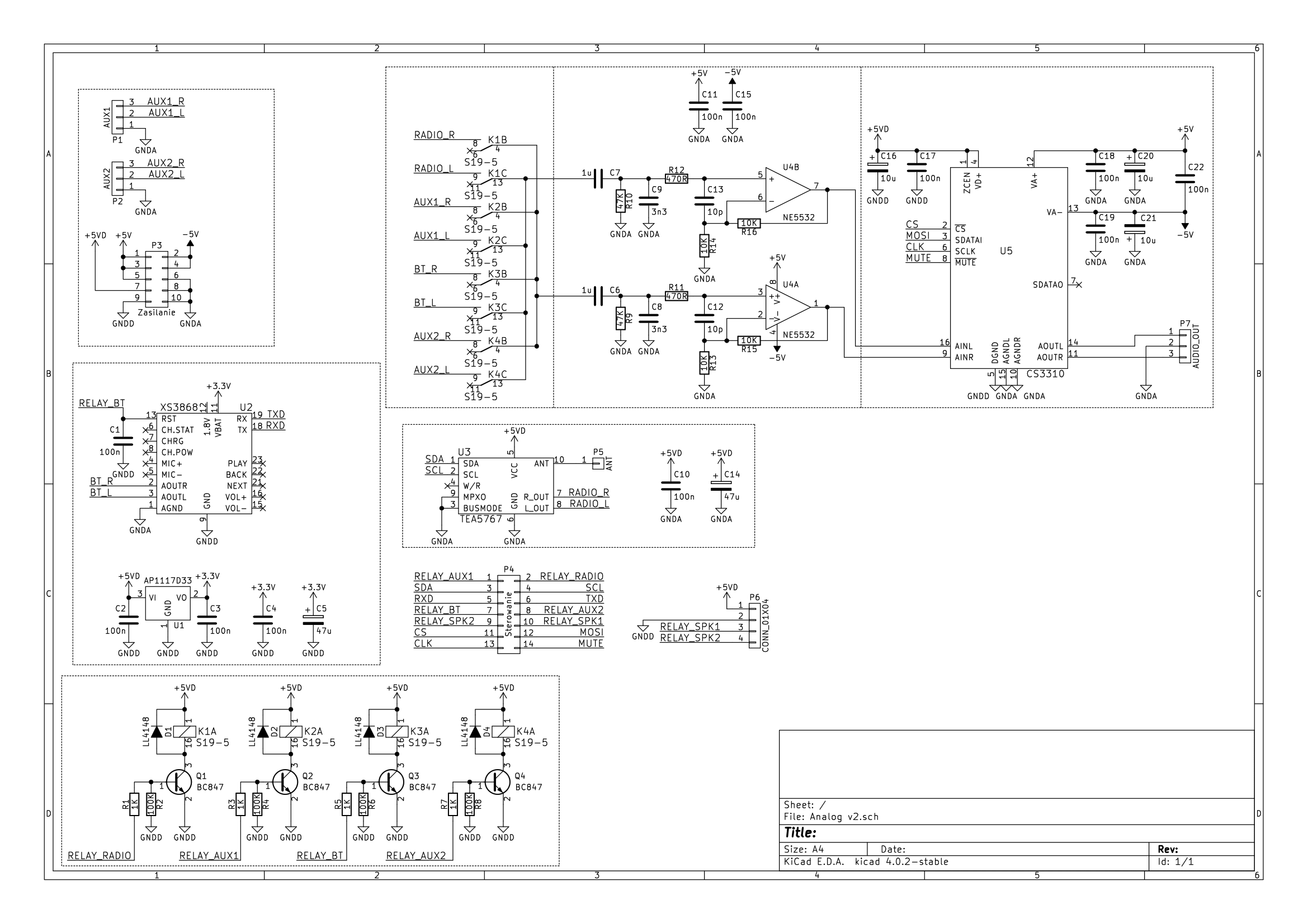
The diagram of the whole is not as clear as I would like, but you can see what it is connected with.
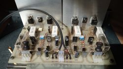
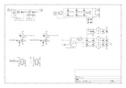
 Power amplifier Copy of ROTEL RA-820 or "hajend for the poor"
 on BD911 / BD912 transistors and here I have to mention my problems with this design. I managed to burn the power transistors twice, once setting the quiescent current and the second time connecting the signal source with the amp on, which was not the smartest thing. I got the impression that the system is very sensitive to mistreatment, according to
front247 Poor quality transistors can cause these problems.
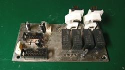
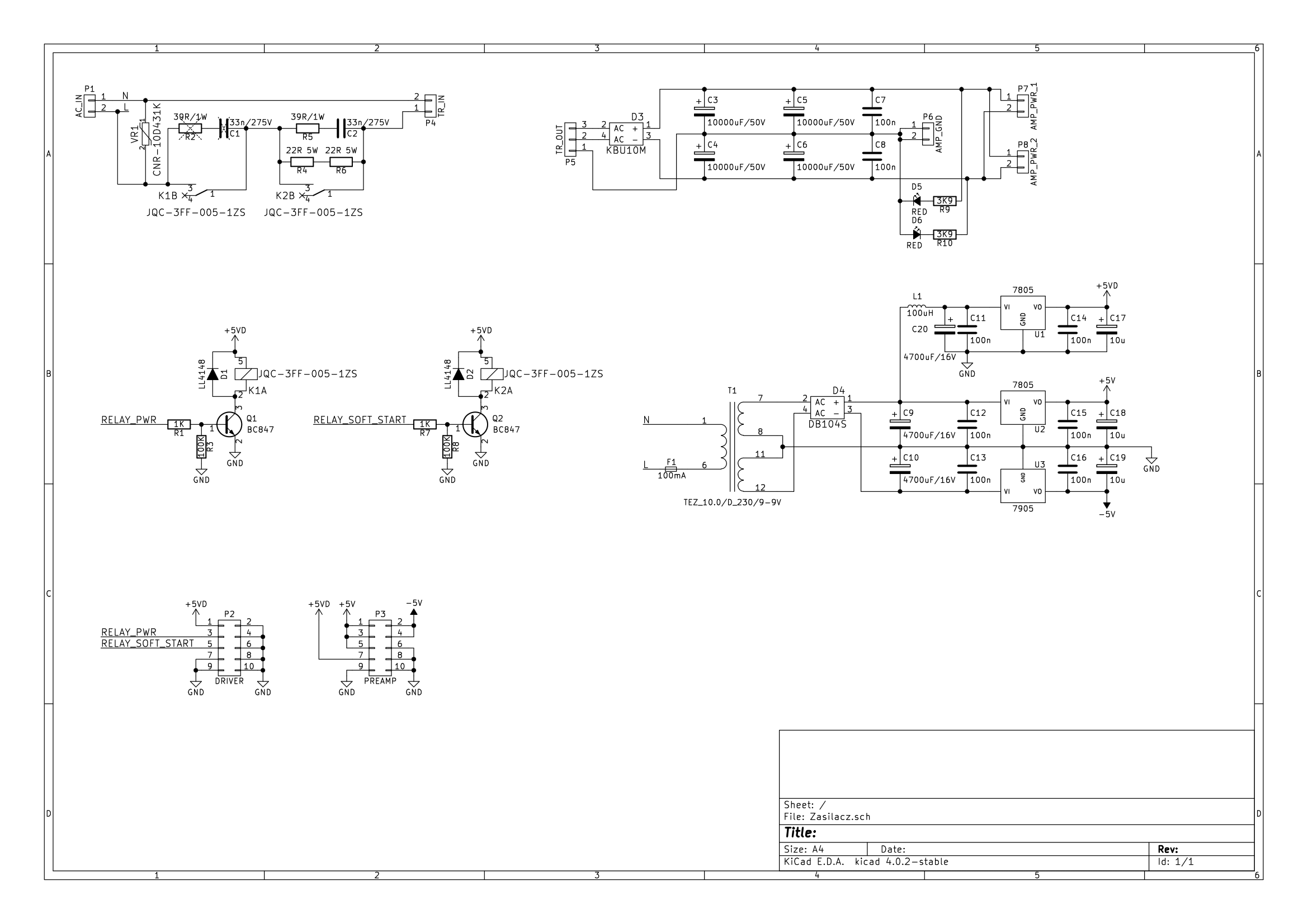
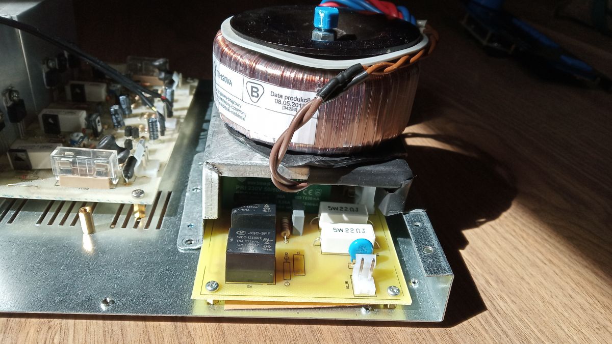
 Power Supply
 The driver and preamplifier are powered by a small 2x9V 10VA transformer that is on all the time. The voltage is stabilized at +/- 5VA to power the digital potentiometer and the preamplifier circuit, additionally by a + 5VD choke to power the digital part and relays. Unfortunately, I underestimated the power lost on this stabilizer and had to put it on a separate heat sink outside the PCB. The relays consume 300mA, which with 9V put on the stabilizer gives 2.7W, it would be better to power the relays from 12V, then with stabilization you would lose only 0.26W
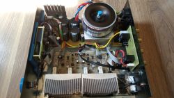
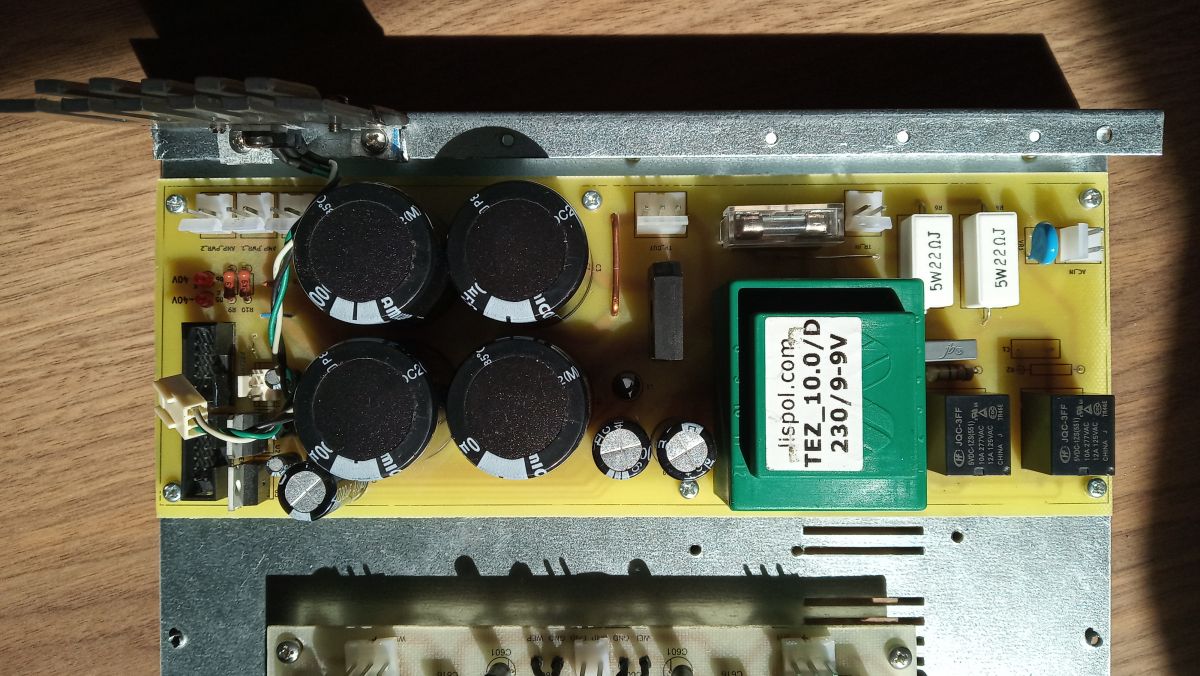
A 2x27V 120VA transformer with two pairs of 10000uF capacitors was used to power the power amplifiers. Relay K1 turns on the power, and K2 closes the soft start resistors, both relays are controlled by the uC.
The tile was designed so that it could be mounted vertically as in the project of my colleague Katakrów, but in the end I had no idea how to do it without using wood.
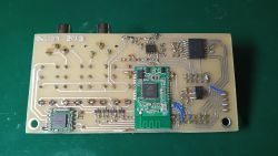
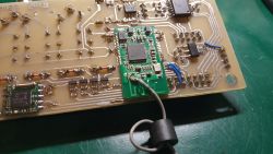
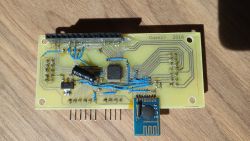
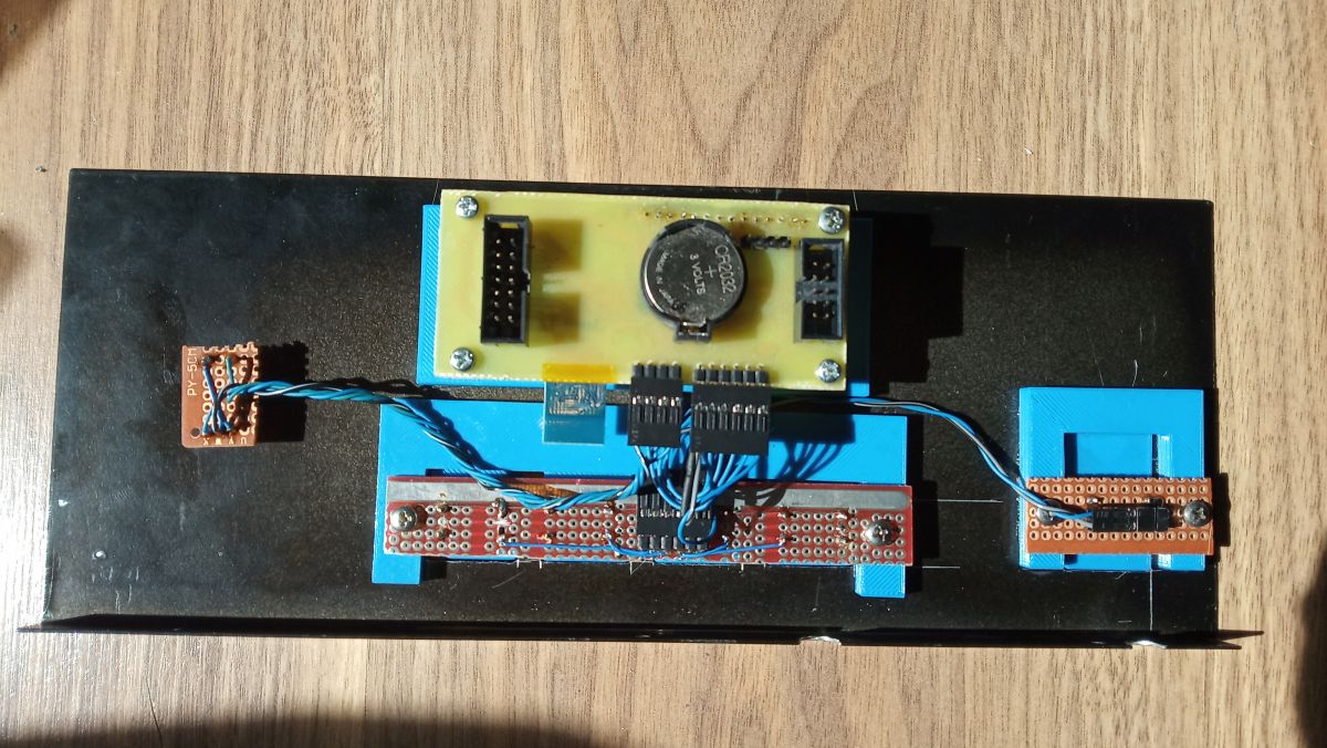
 Preamplifier
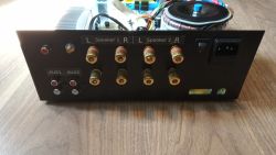
 The board with the input selector, digital potentiometer and radio modules allows switching between four signal sources, AUX 1, AUX 2, Bluetooth and radio. Bluetooth implemented on the XS3868 module is turned on only after selecting it as the source, you can jump between songs with the right / left buttons. I tried to change the name and password with uC, unfortunately to no avail. OVC3860 is a nice and cheap module, which can be used as a standalone module or with AT commands to change songs, volume, etc. but changing such a basic thing as the name requires a lot of effort, I do not understand why it could not be done from AT commands. Out of curiosity, I checked how much I gave the external antenna, without the RSSI -90 antenna, with the RSSI -55 antenna at a distance of 1m. FM radio on the TEA5767 module, the frequency is changed with the right / left buttons. The CS3310 digital potentiometer with a preamplifier and a set of filters is taken from the project of my colleague Katakrow, I only changed the amplifier to NE5532. The program does not use the chip amplifier section.
The common ground for the digital and analog parts is the spout on the top PCB layer; I was not sure if it was a good idea, especially since the lack of space did not allow me to arrange the individual modules in an optimal way, but the whole thing works very well, I can not hear any interference from the digital part.
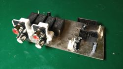
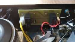
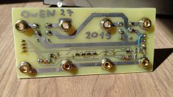
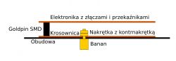
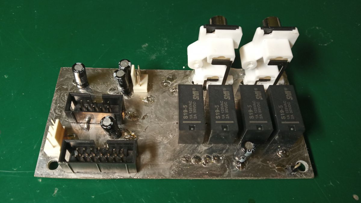
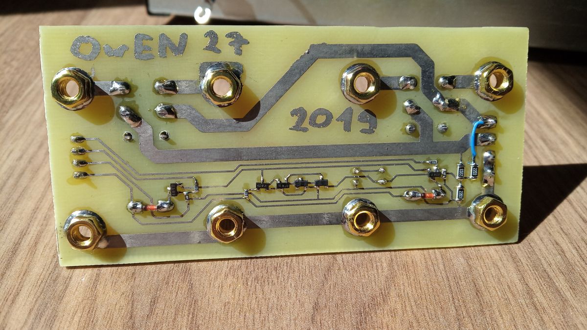
 Speaker protection
 DC component protection connected to the speaker output selector, banana connectors are screwed directly to the board. Unfortunately, sometimes the speaker connectors do not touch, the counter nuts are missing, it should be done as shown in the picture.
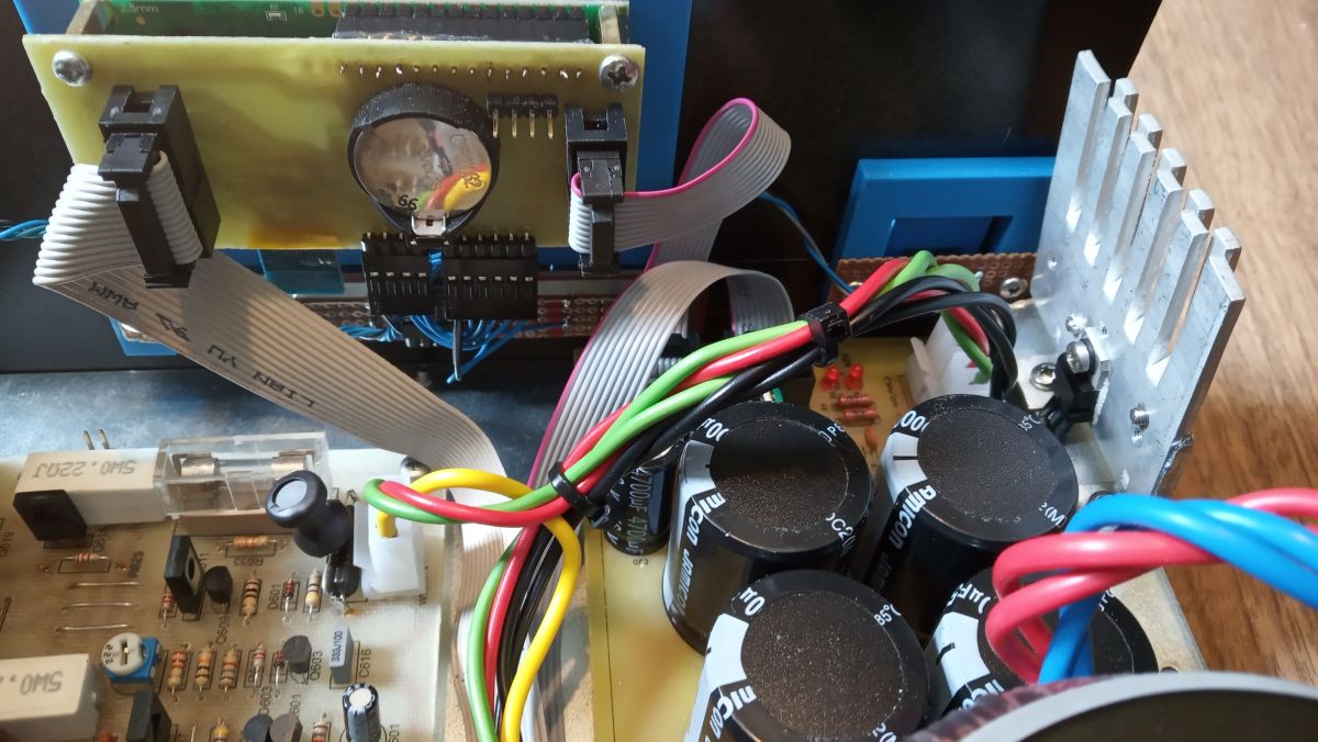
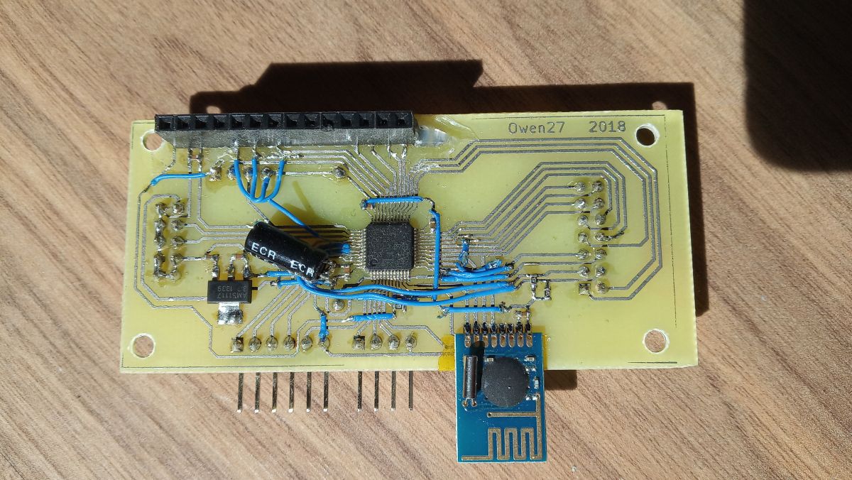
 Controller
 The driver is based on the STM32F100C8T6B microcontroller, of course there is no need to use a 32 bit processor, I chose it to gain experience with STMs. There were plans for a remote control on NRF24L01 modules, which never happened. The blue OLED 16x2 display looks very nice, after two years I did not notice any burned-in pixels, so also a plus. The volume and I / O selector settings are stored in the built-in volatile memory with a 2032 battery, which eliminated the need to detect a power failure. There is terrible tinkering on the tile, it works but it looks disgusting, next time I would outsource it to a tile mill.
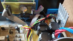

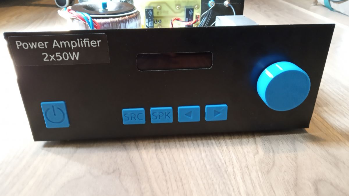
 Housing
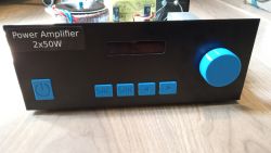
 T-268, it was tighter than I expected, the transformer had to be placed above the power supply board, there was nowhere else to go. The advantage of the housing is certainly its width, at 260mm it fits into narrow cabinets. The buttons and the potentiometer knob are made of PLA, together with the blue OLED they contrast nicely with the black casing.

 Summary
 The amplifier has been working without any major problems for two years, sometimes the program freezes and this is where the switch on the back comes in handy

. More generally, the outputs of the processor are not even protected by resistors, and the signal strips run next to the power cables and output power amplifiers, strange that the processor is still alive. It is also worth adding ferrite beads on the uC power supply and modules on the preamplifier board. BT after some time without the paired device goes into some sleep mode, which cannot be woken up by the switch or the input selector, you need to use the main switch. It is possible that disconnecting the power supply with the transistor would solve the case, I don't know, I didn't check.
After moving, he began to hum softly, he probably does not like the new apartment


Comments
What was the security layout inspired by? [Read more]
Fragment of the unizab1 project, Link I just don't remember why I used two capacitors. [Read more]
1. The heat sinks of the power amplifier 'sit in the housing' with the airflow between the fins blocked (top and bottom), what temperatures do they reach at 50 and 100% power after five minutes? ... [Read more]
Only the inscriptions embedded in them will collect dirt over time and there will be a problem with cleaning. Additionally, in combination with the sticker, the whole thing looks "workshop", but I have... [Read more]
Congratulations on your persistence. As for the above, long signal / control connections between the boards make the circuit susceptible to hanging, e.g. during the operation of relays. High voltage pulses... [Read more]
Hmm, 120 VA and soft start? You can, why not, but in this case an unnecessary circuit for such a low power. [Read more]
Well, I would not try to copy the Rotel on these transistors. One that in my opinion they are not suitable for this at all, and two that they are often counterfeit. I was making copies of a slightly different... [Read more]
Maybe the author will forgive me for littering the subject, but I have such a question, because I am just finishing building the power amplifier myself and I have a problem with humming from the traf.... [Read more]
Make a sheet of metal screen around the trafo or pour resin into a metal "cup". [Read more]
There are vents under the heat sinks and on the top surface. The gaps in the buttons can be poured with paint, but I do not know what. I don't know if optocouplers are necessary, the RC filter should... [Read more]
They are not, but they are definitely a good option. Well, it's always a good idea to consult a component's documentation before using it. Are you happy with this BT module by the way? I... [Read more]
No sheet metal screens, because that won't help. I already had such ideas and I received such equipment with a request for help, because everything is supposed to be well and buzzing. If this is not... [Read more]
Unfortunately, it doesn't do anything, you can turn it around. [Read more]
Hello, I think that the fault for the burnout of the power amplifier is not on the side of the transistors. There may be something wrong with the diagram. When connecting the signal source with the power... [Read more]
I recently repaired a 30 year old guitar amp using BD911 / 912 transistors. It worked without any problems for many years. Later, fault after fault - the BDs were still exchanged and it was the first distortion... [Read more]
A friend deigns to joke? There is no need to pick on the Rotel tip diagram, which was the standard, because it is a proven design. Well, unless my colleague, the author redrawn the diagram incorrectly,... [Read more]
I would be more inclined to the opinion that it is difficult to find the original BD911 / BD912 now. As these are general purpose transistors, various "garbage" can be labeled as long as the housing is... [Read more]
Yes, the current BD911 / BD912 is completely different than it used to be. But despite everything, I remember from my experience from years ago that the amplifier with them was not very musical, and switching... [Read more]
Exactly, once I repaired a Unitra amplifier, I ordered these BDs, replaced the controls, everything was fine, I turned it on, even checked it, but as soon as I increased the volume a little - buuummm.... [Read more]