Smart light switch dimmer QTouch WiFi [Schematic, UART protocol].
TL;DR
- A QTouch WiFi light switch dimmer, sold as QBP.DIM.WIFI, is torn down, paired with eWeLink, and reverse-engineered into a schematic and UART protocol.
- Inside are an ESP8285, UTF87001, and HD6001; the UTF87001 handles dimming and button logic while the ESP mainly mediates WiFi and status LEDs.
- The UART link runs at 19200 baud, uses ESC 27 as the packet delimiter, and the mains stage uses a BT136S-600E triac driven by an MOC3021.
- Desoldering UTF87001 unlocked ESP flashing with esptool.py and Tasmota, but the dimmer still worked through UTF commands, and RF433 support turned out nonexistent.
Generated by the language model.
 .
.
Hello my dears. .
Here I will test a 'smart' WiFi QTouch light switch/dimmer, pair it with the eWeLink Android app, analyse its design, demonstrate tapping into its communication protocol on the UART (communication between ESP and UTF microcontroller) and draw a schematic. I will also reveal the big inconsistencies between the actual product form factor and what the vendor promises. This will be the second topic about the QTouch series. Finally, I will also try to extract the password and SSID of my WiFi from the batch of its ESP, we'll see if it works.
Previous topic about QTouch .
I have previously drawn a diagram of a QTouch switch, but a very different one.
The one previously tested stood out in that it plugged into the L wire (no N) and surprisingly worked, including WiFi. Its circuit was quite cleverly implemented, details here:
https://www.elektroda.pl/rtvforum/topic3793509.html
The switch I'm about to present requires both N and L to be connected, and in turn stands out because it offers dimmable lighting (of course, it's based on a triac, so it won't work with any bulb).
Purchase the QTouch Quadra dimmer .
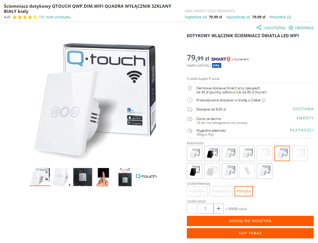
I bought the product in our country through a mail-order portal for PLN80:
 .
.
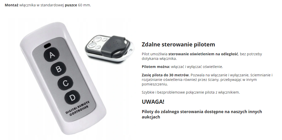
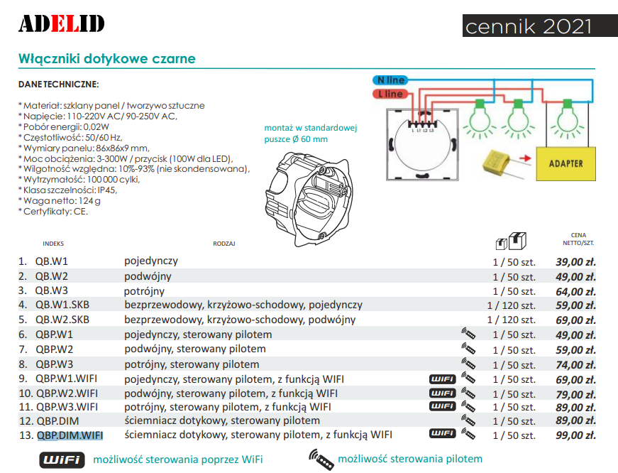
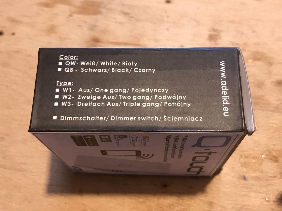
The switch is advertised as supporting WiFi and 433 RF remote control (note: in reality the remote control does not):
 .
.
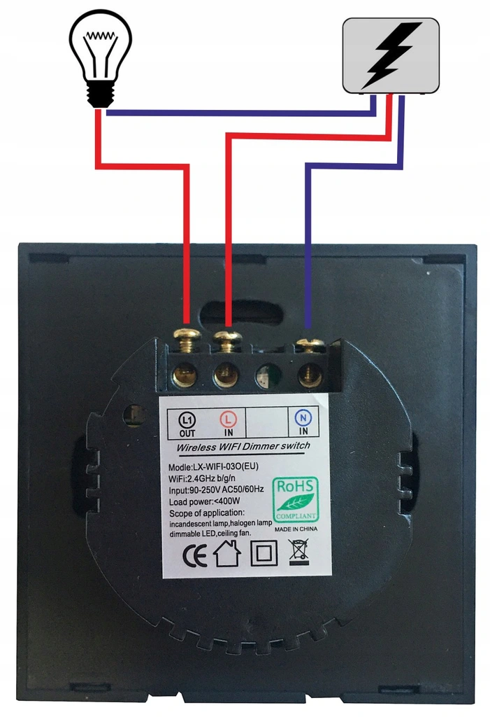
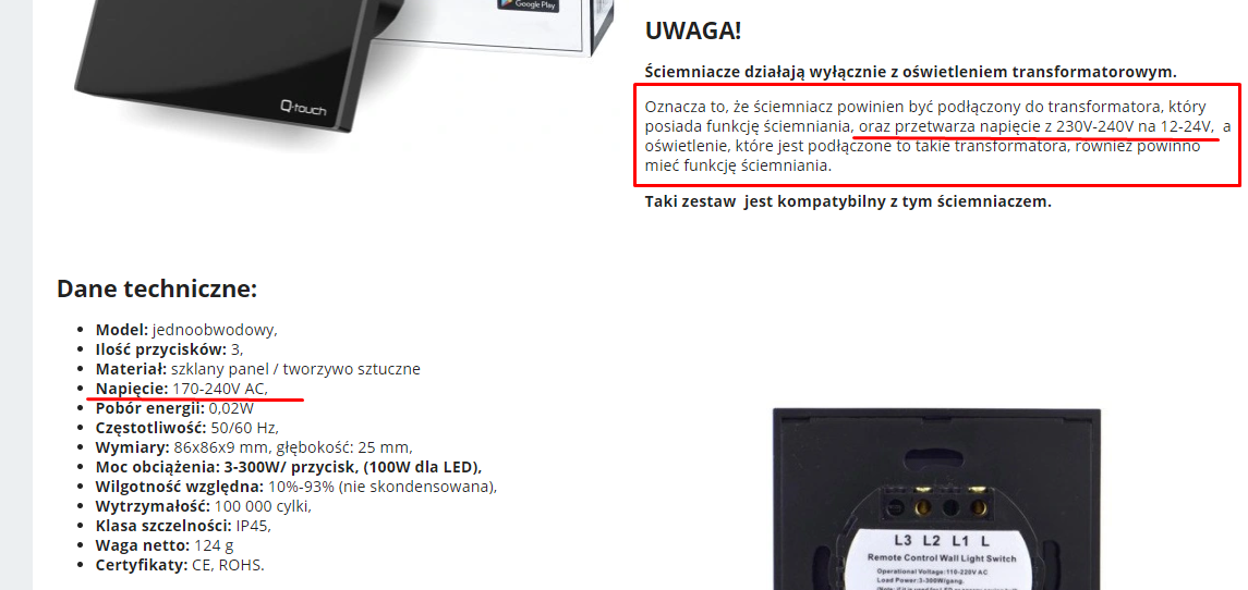
The seller provides the correct installation diagram of the switch (this is quite important, because the manual included in the box has an incorrect diagram !!!):
 .
.
But there is other incorrect information on the seller's quotation. The seller first suggests that this switch is connected on 12/24V and then states that the operating voltage is 170-240V....
 .
.
I didn't agree, so I quizzed the seller on this, but the seller confirmed that this switch does not work on 230V and requires a transformer, and that each of its three buttons (brighter, darker, off) can be paired with a remote control:
 .
.
Apparently the manufacturer's brochure also highlights that this product has RF433:
 .
.
Is the vendor correct? What is it like in reality?
It is time to find out.
Content of the kit .
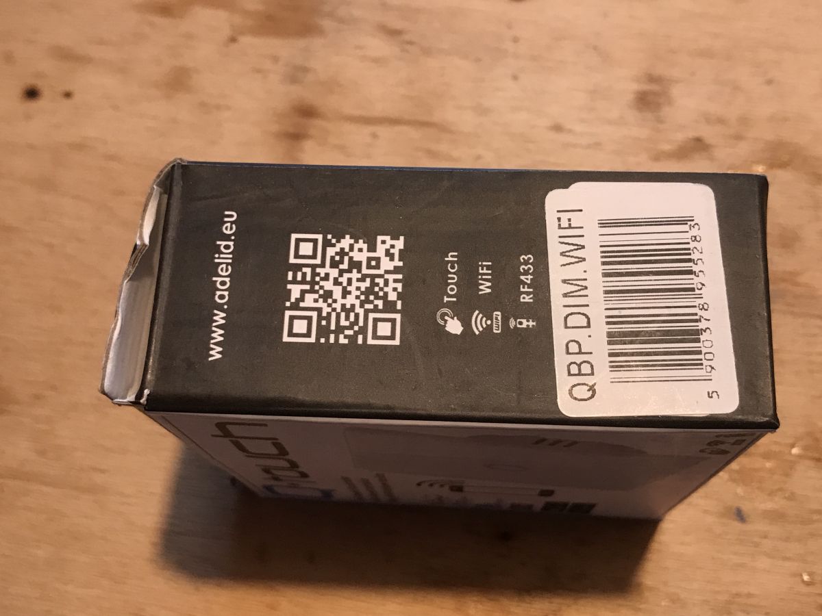
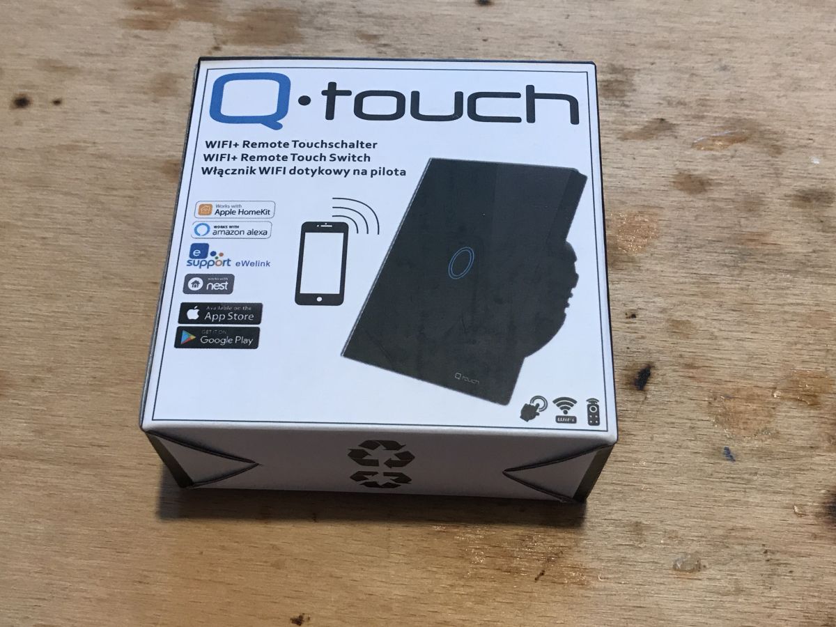
It is clear from the product packaging that communication via WiFi and RF433 is supported:
 .
.
Product code: QBP.DIM.WIFI
Inside we have instructions, a switch and a capacitor....
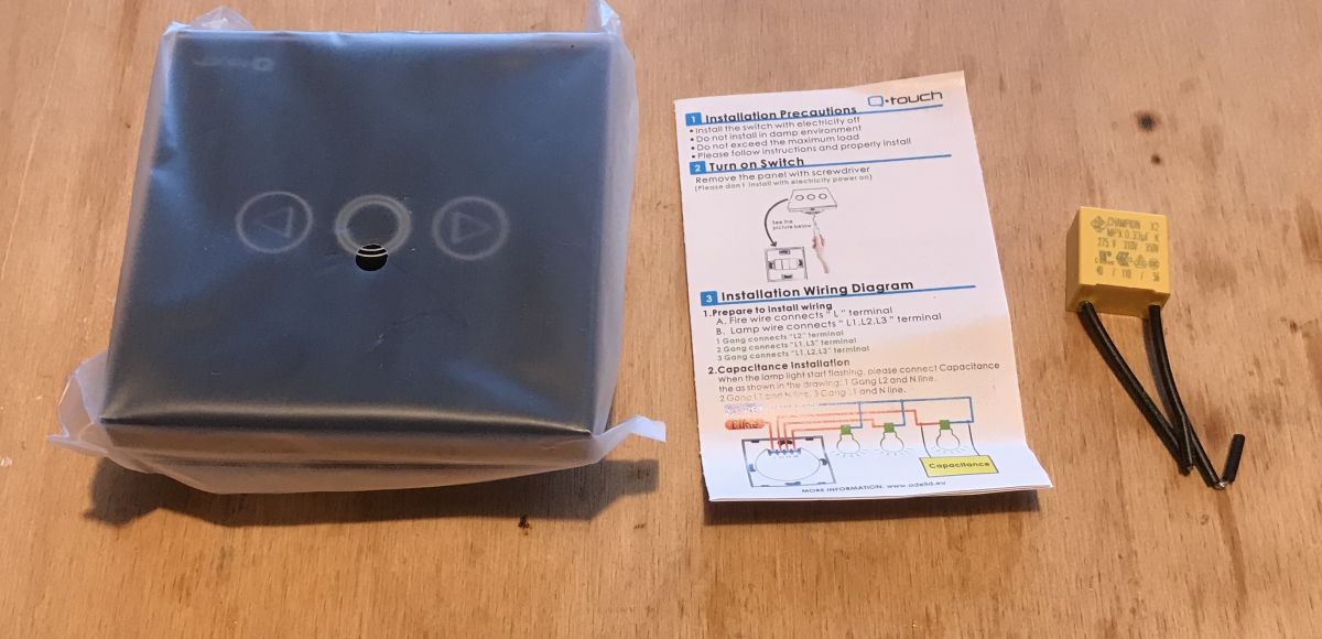
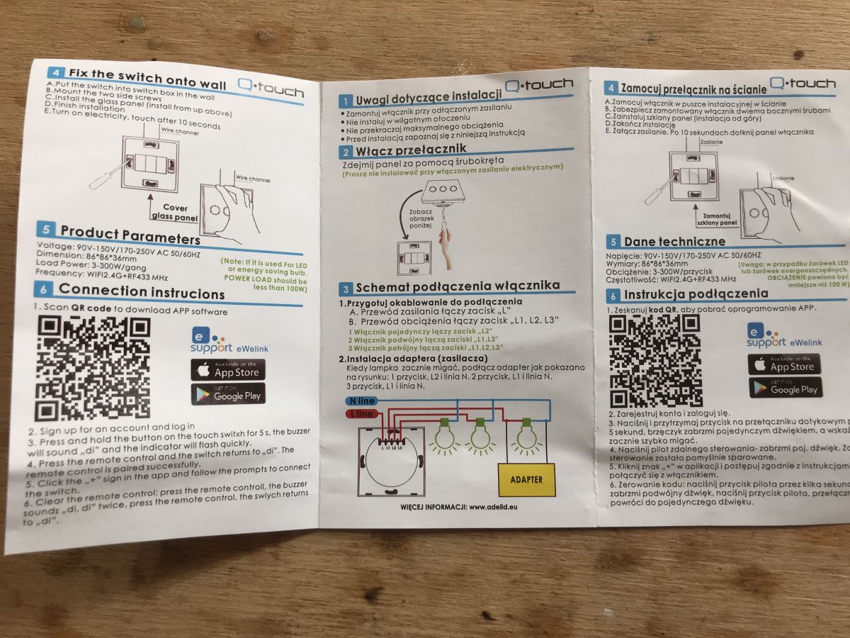
The manual, unfortunately it does not apply to this product. These instructions are for a switch that does not need a zero connection (plugged into the phase), not for a dimmer:
 .
.
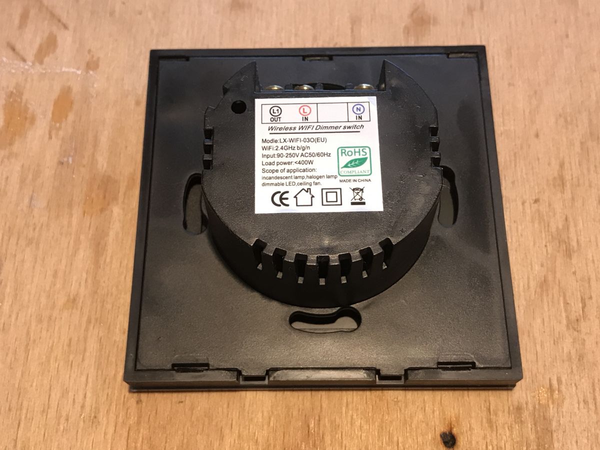
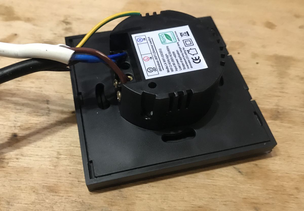
Rear:
 .
.
There is a different product code on the case to the one on offer. LX-WIFI-03O (EU) . Under this heading you can find offers from outside our country. There is nothing about the RF433 in them.
First commissioning .
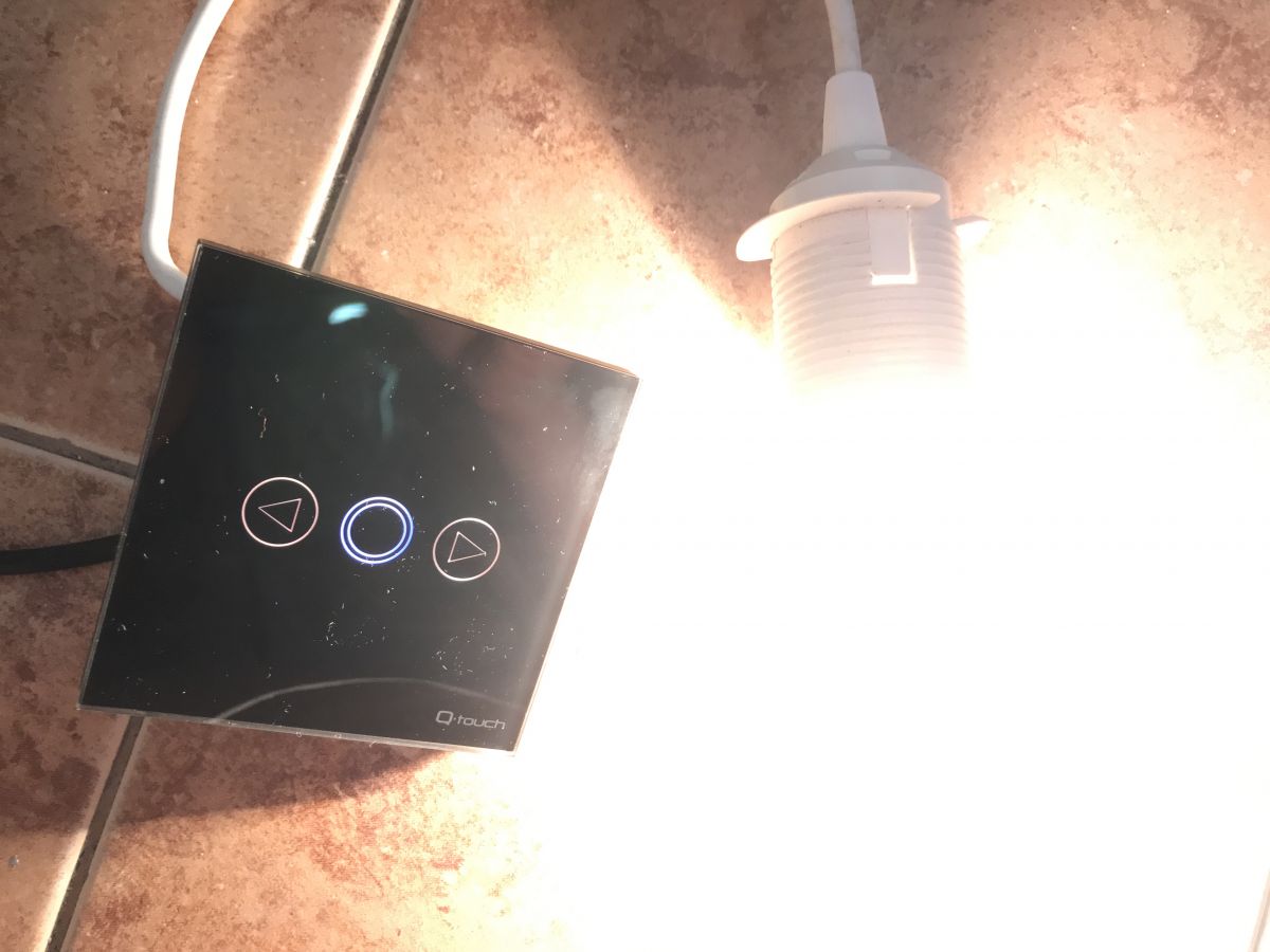
After assembly (according to the instructions from the website, not the one from the box):
 .
.
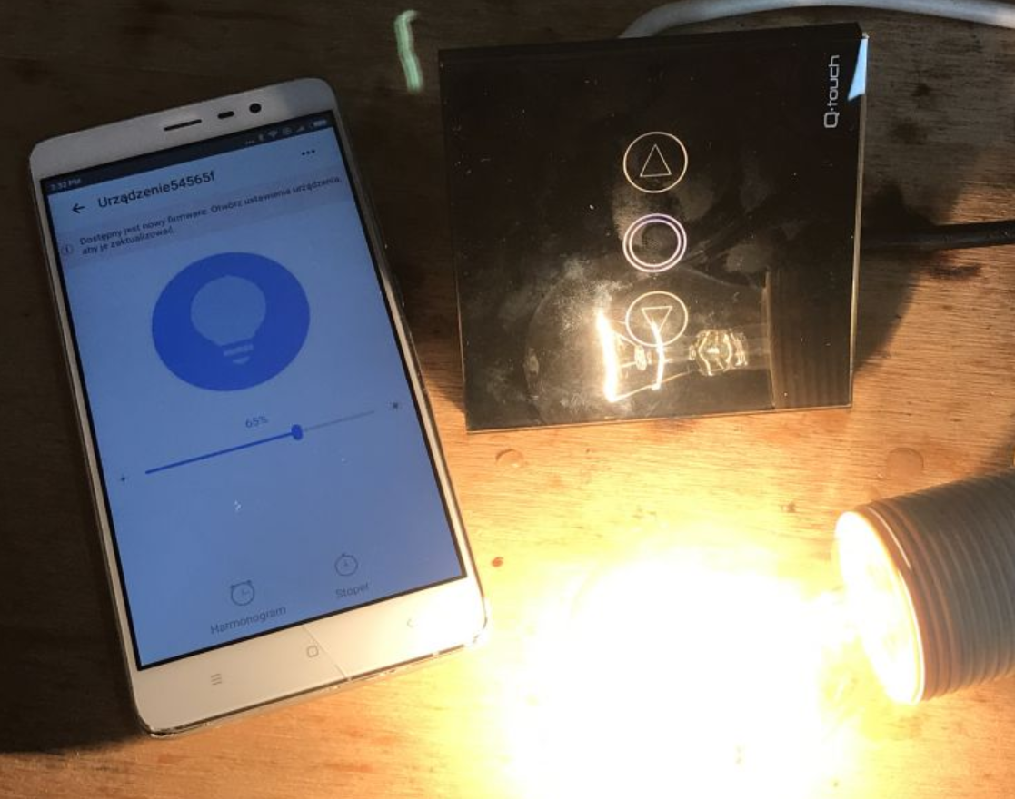
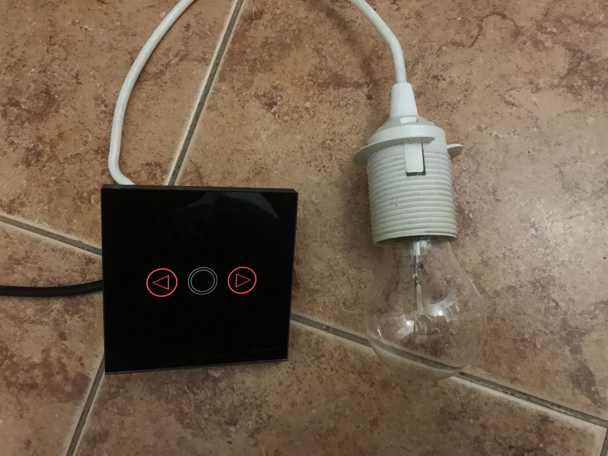
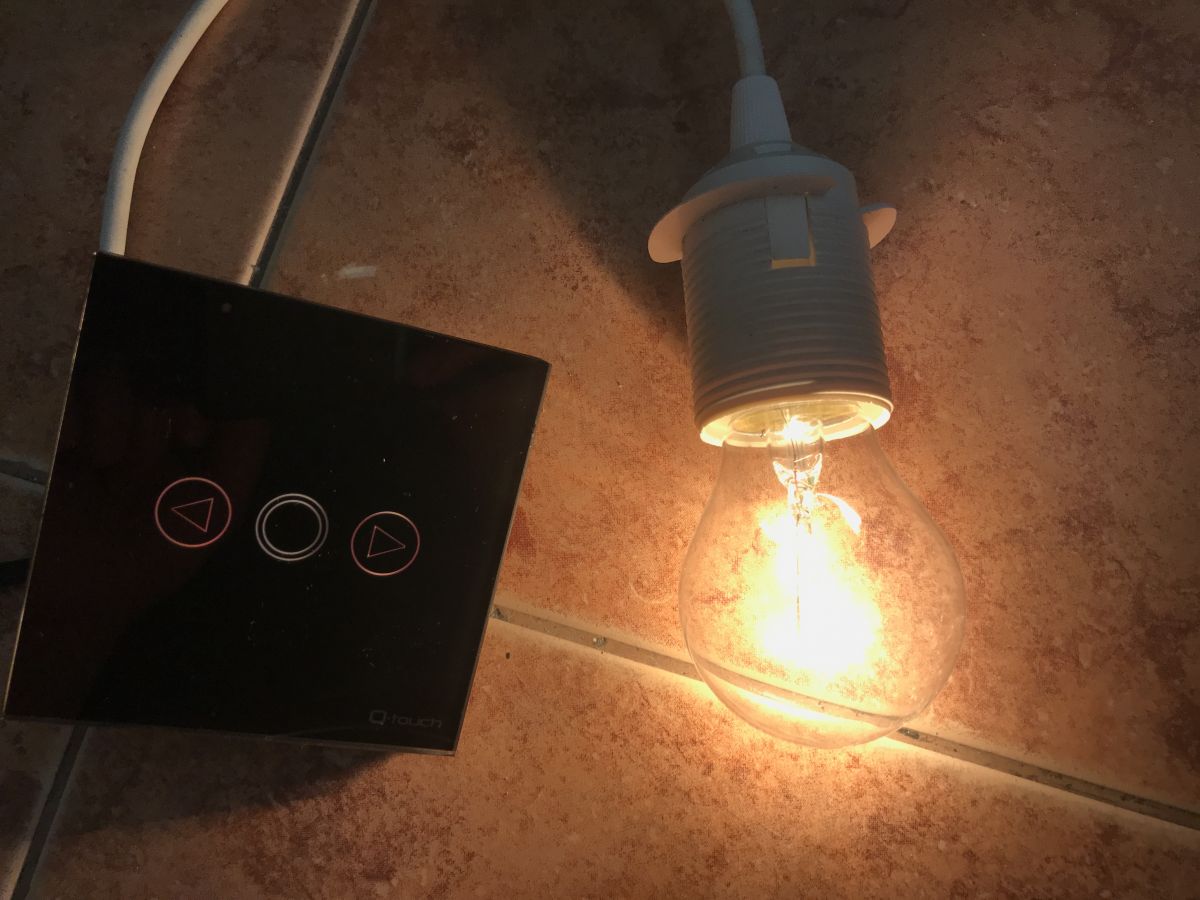
The buttons are illuminated, in my opinion the whole thing is quite aesthetically pleasing and I like it.
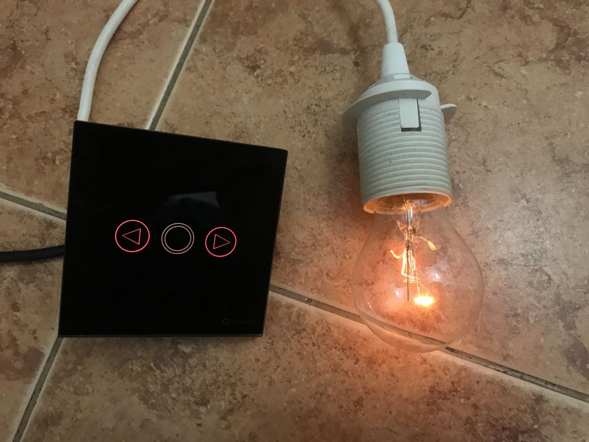
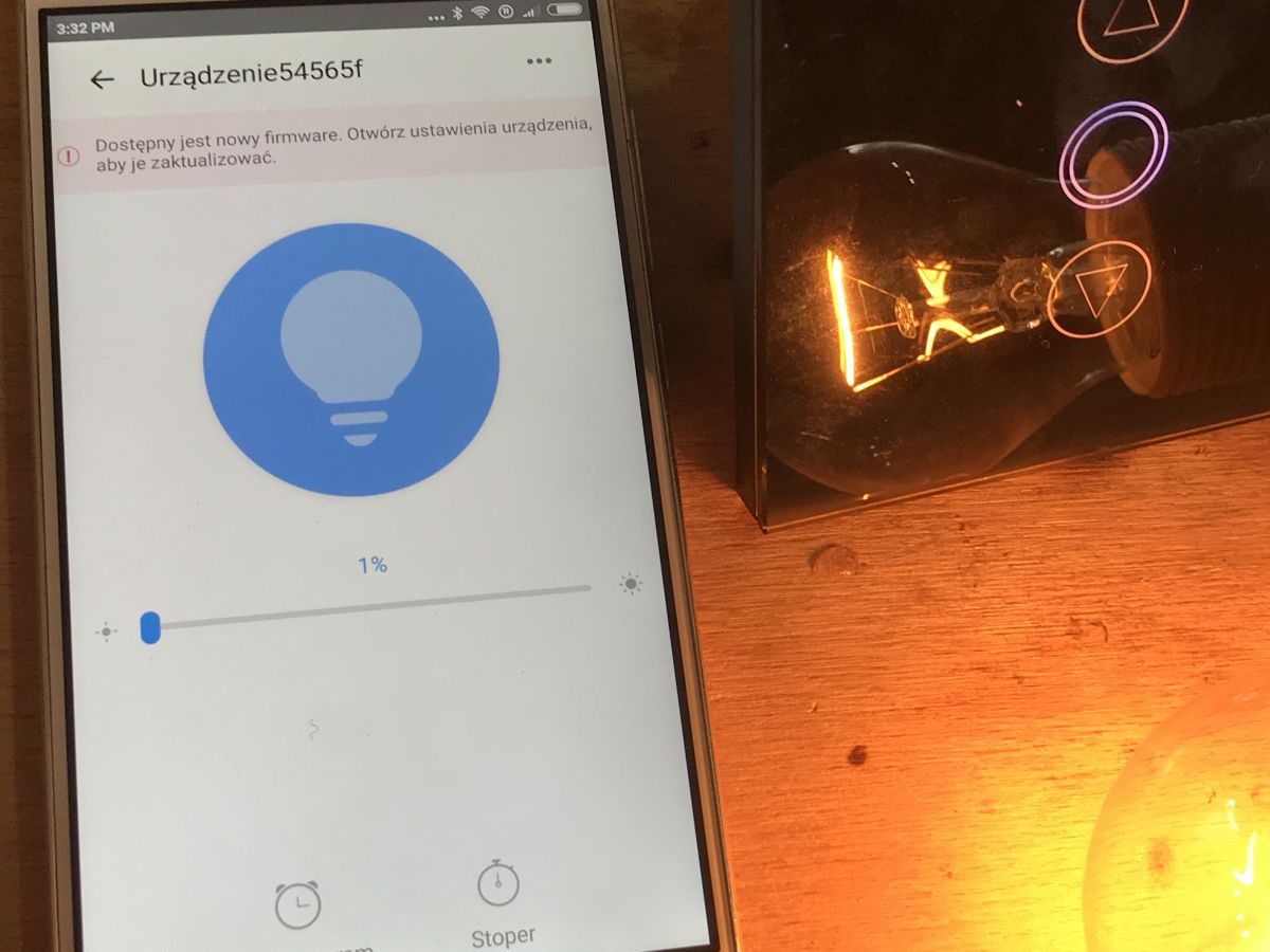
The buttons respond quite slowly, but the dimming is smooth, but not from 0.
 .
.
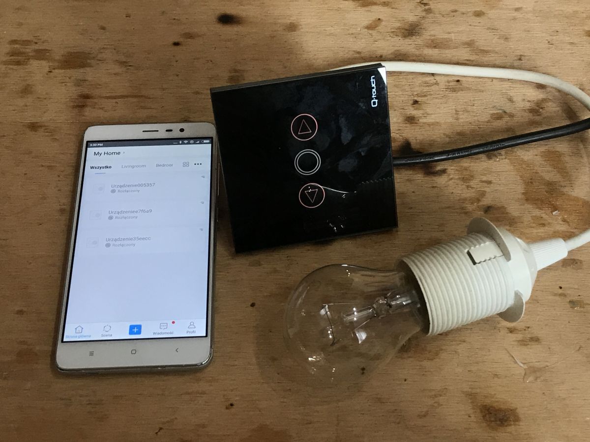
Pairing with eWeLink app and phone control .
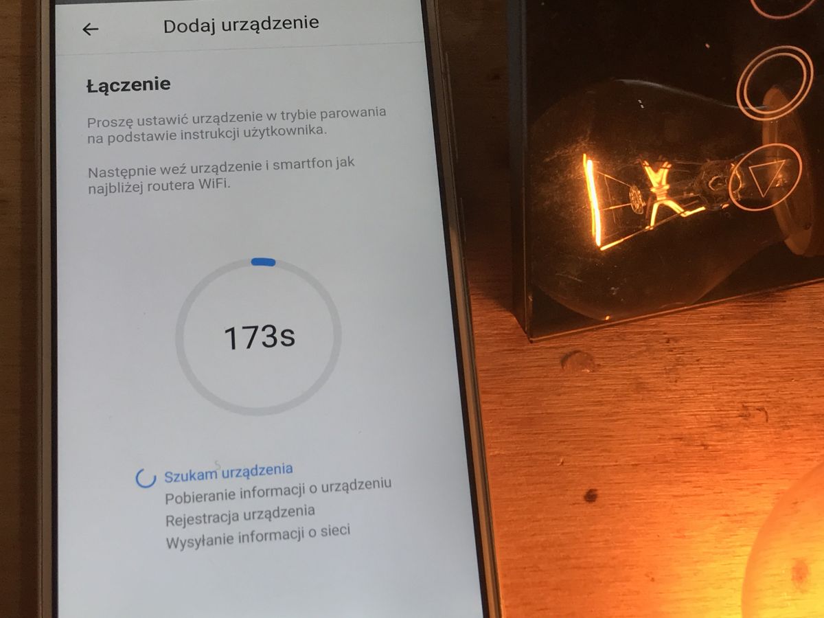
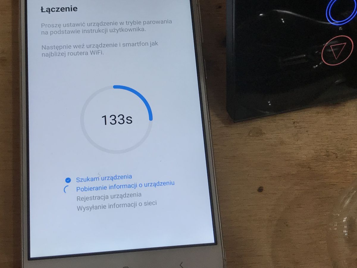
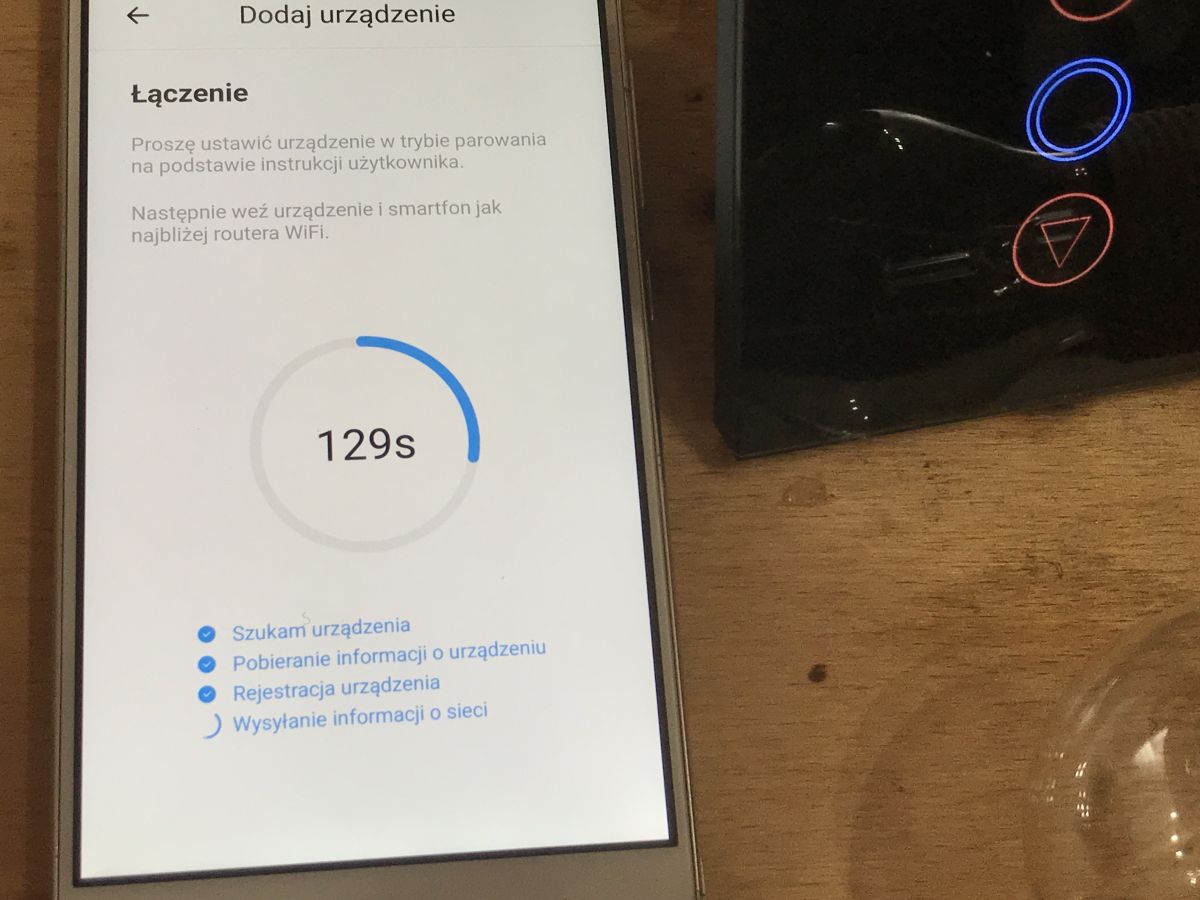
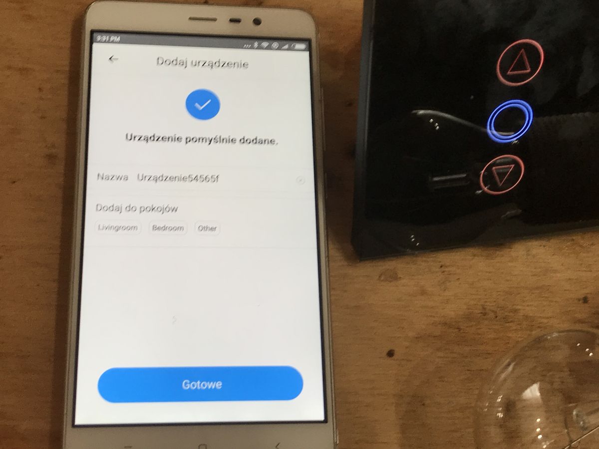
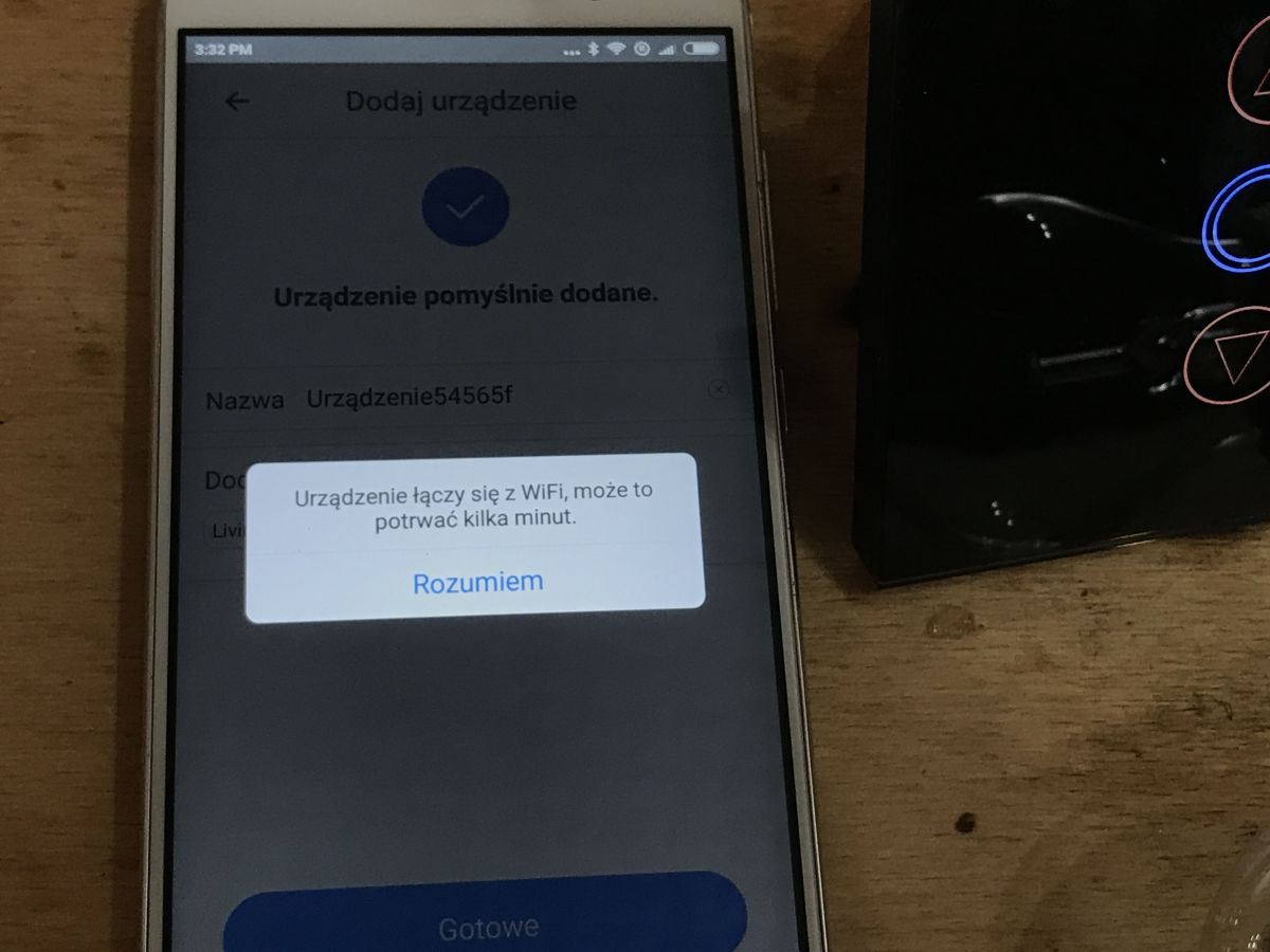
Before pairing, put the unit into RESET mode by pressing the button for a long time (until it starts flashing rapidly in blue).
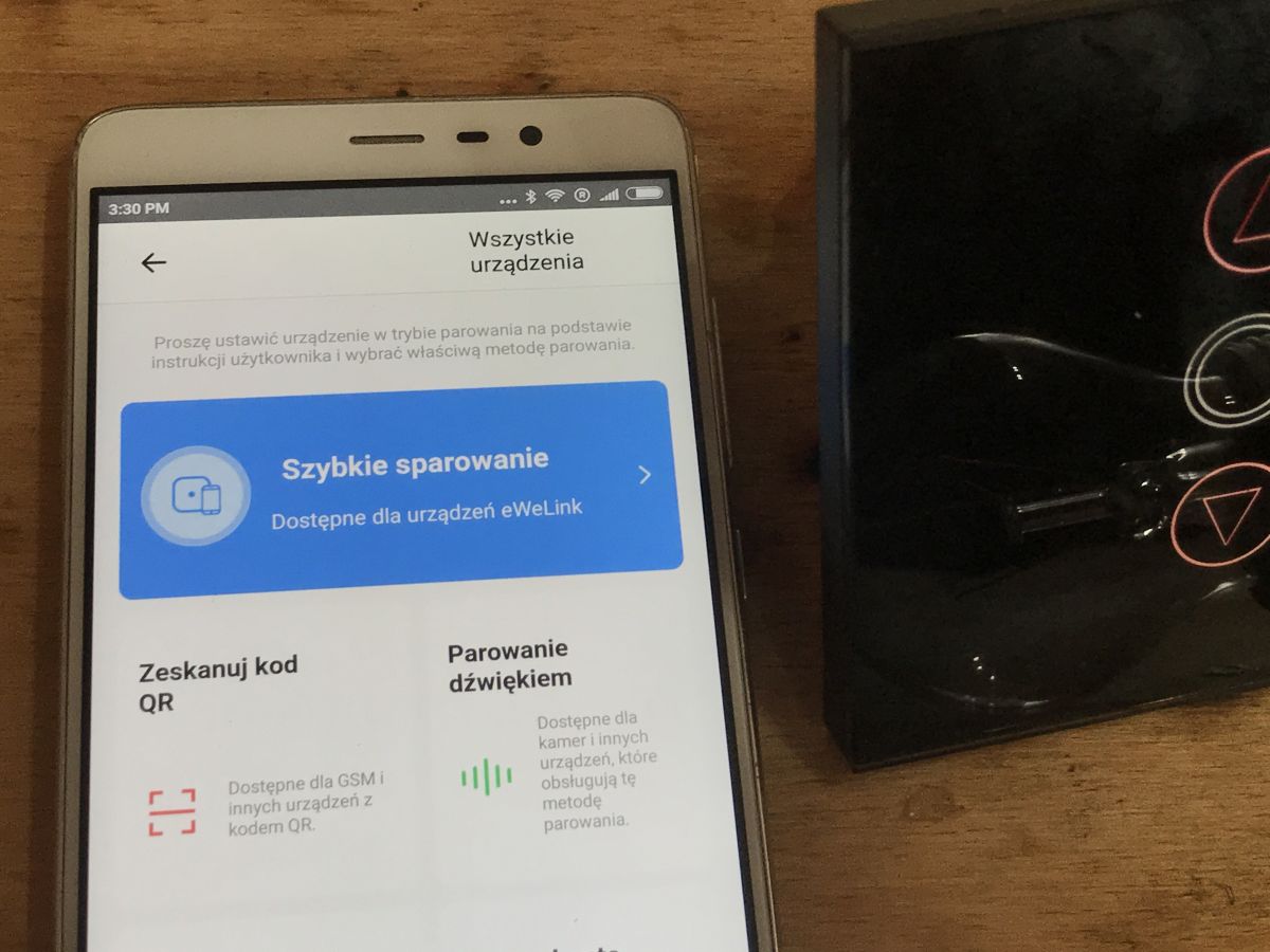
Pairing works in "Quick Pairing" mode.
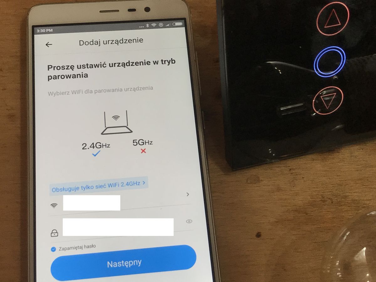
Pairing requires the SSID and password of our WiFi (2.4GHz only supported).
I have covered the Smart device applications in detail in previous topics in this series.
Step-by-step screenshots of the pairing:
 .
.
 .
.

 .
.
 .
.
 .
.
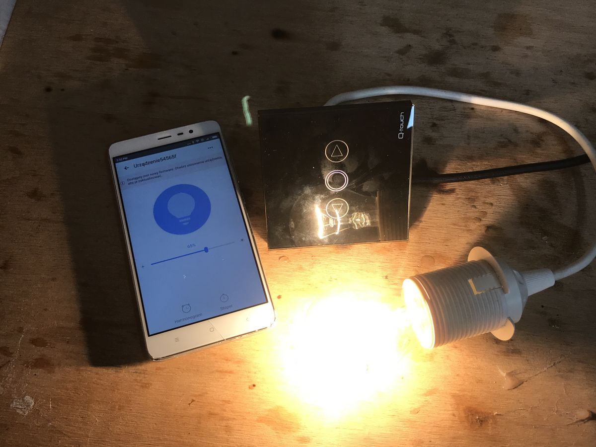
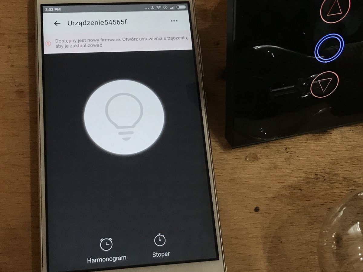
The application offers an interface as below (you can control the brightness with a bar, from 1% to 100%):
 .
.
If you are interested in learning more about the Switch Control application, I recommend checking out these topics:
https://www.elektroda.pl/rtvforum/topic3687040.html#18652154
https://www.elektroda.pl/rtvforum/topic3749207.html
Admittedly, it is about a different application there, but they are very similar
Pairing with RF433MHz remote .
I was unable to pair this QTouch switch with either of my remotes, although the other QTouch (but without the dimmer) worked with the remote without any problems.
My remotes:
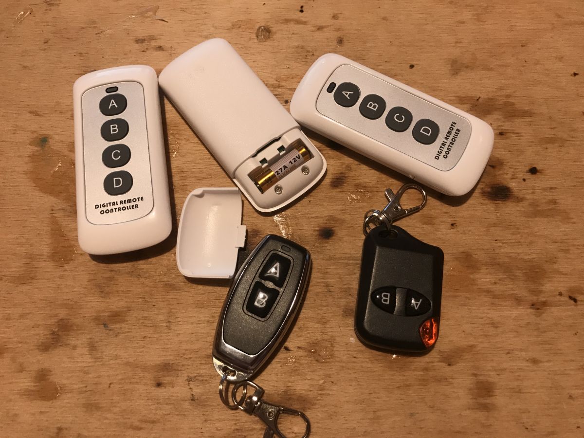 .
.
I suspect that this QTouch with dimmer does not support RF though (and an analysis of its board confirms this, but more on that shortly)
Inside of the dimmer .
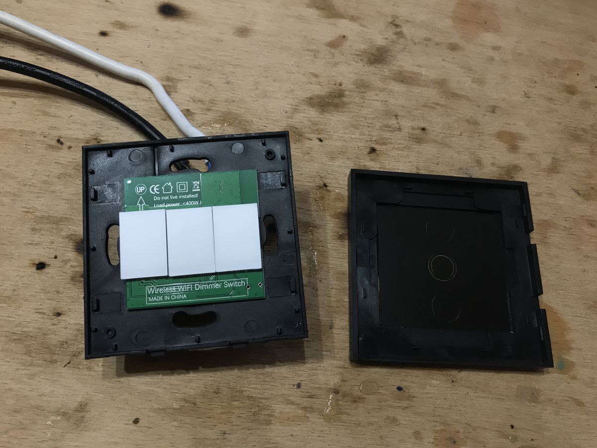
It's time to take a look inside. The front panel can be removed by levering it up with a flathead screwdriver.
 .
.
The panel with the ESP is simply removed (although I think it was also slightly glued on):

 .
.
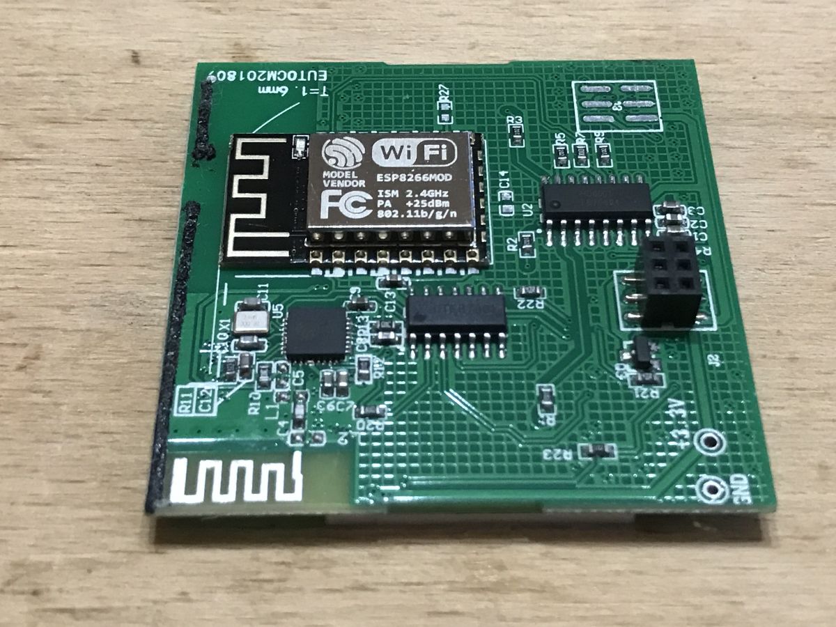
Interior dimmer - board with ESP .
This board only has low voltage circuits, 3.3V. Its role is to handle communication via WiFi, the dimming process (but the triac that performs the dimming is on the other board) and the touch buttons.
 .
.
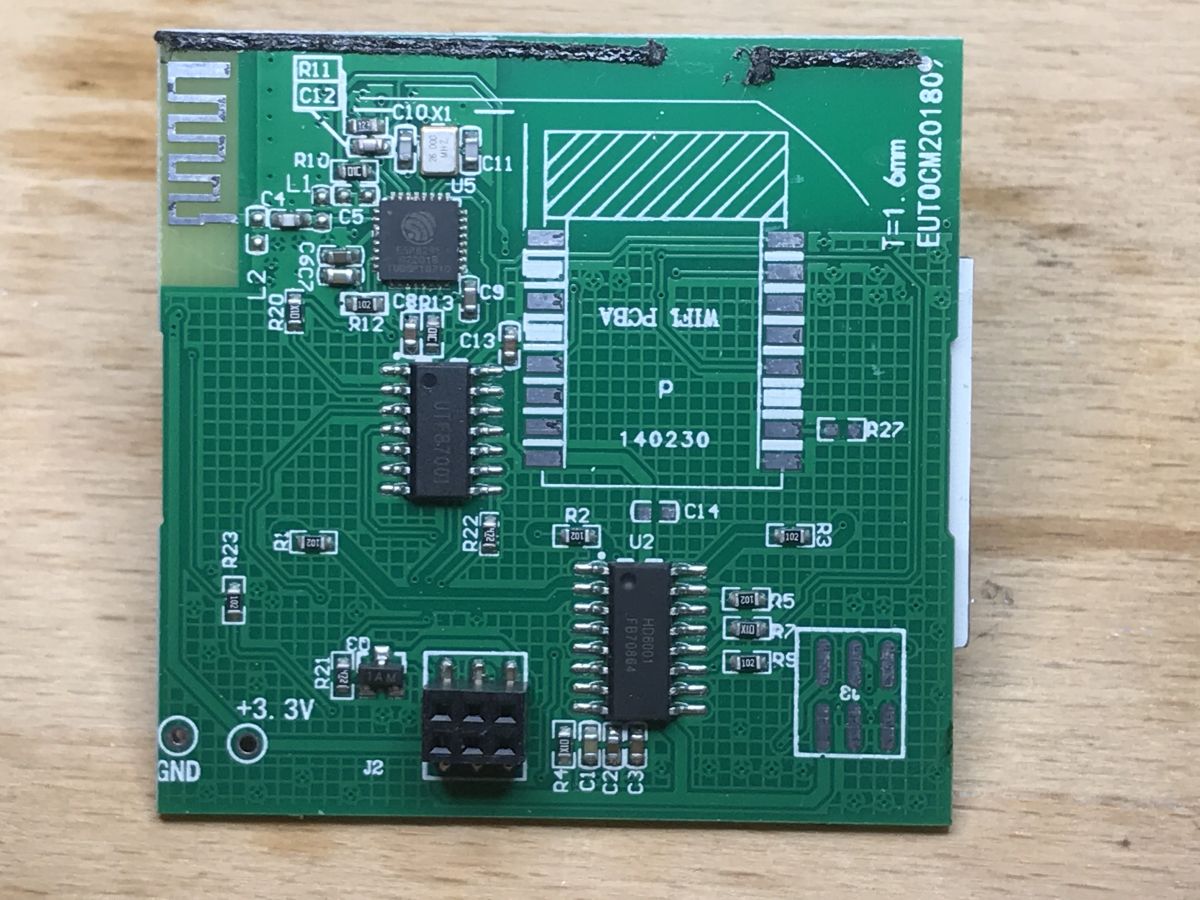
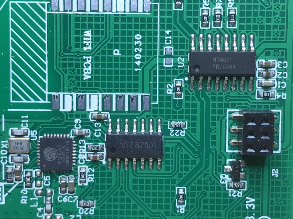
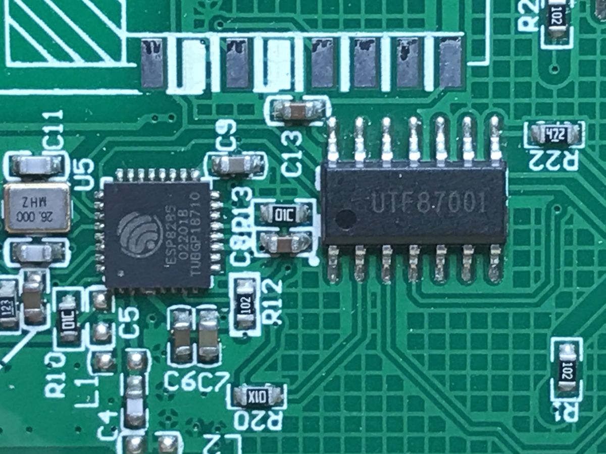
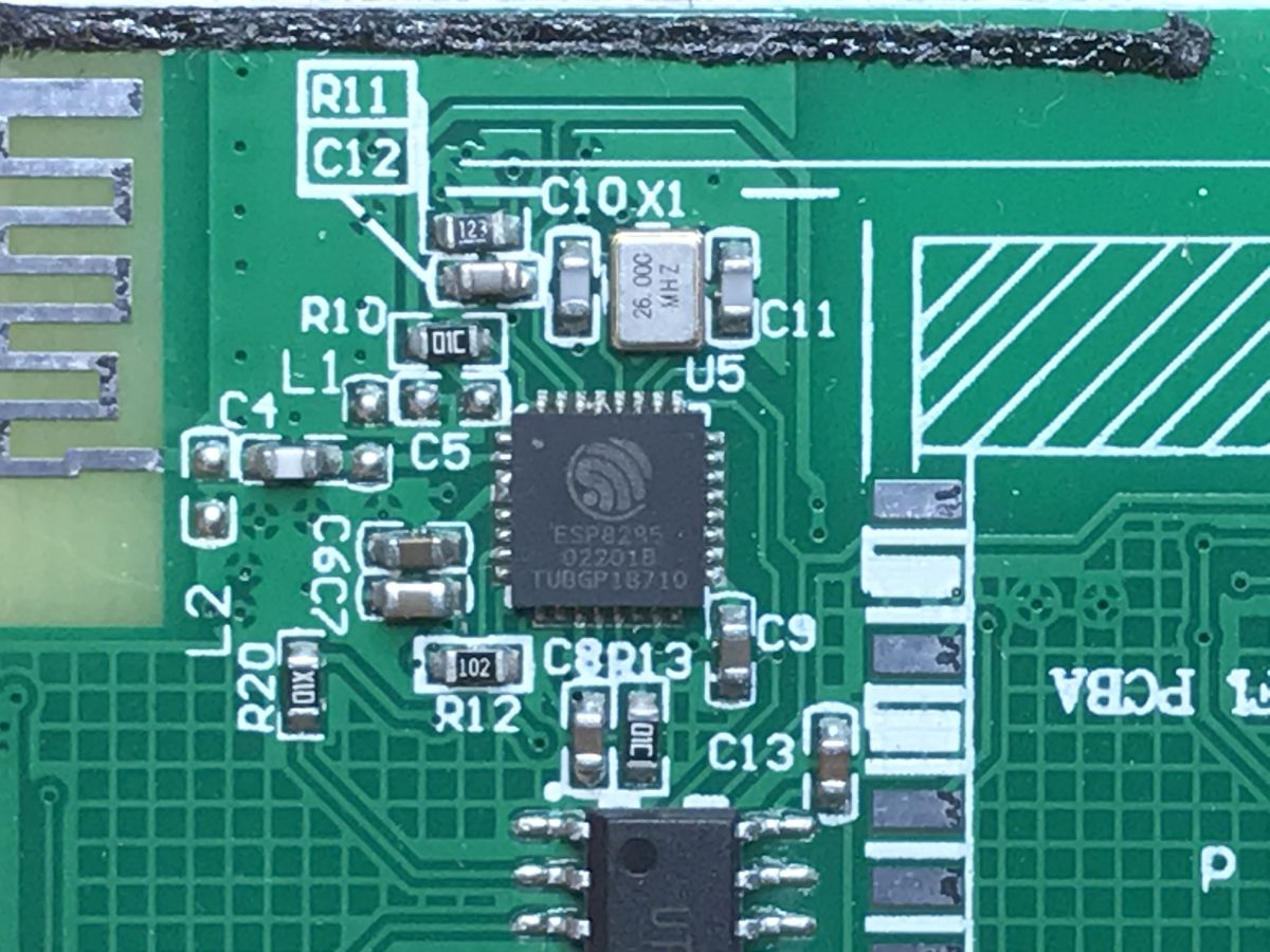
Here we have the ESP8285 (i.e. ESP8226 with built-in Flash memory), UTF87001 and HD6001.
 .
.
HD6001, touch button microcontroller. Yes, a microcontroller, not a simple touch button chip.
 .
.
 .
.
 .
.
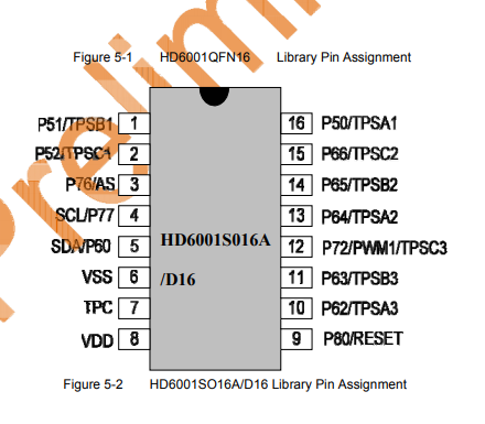
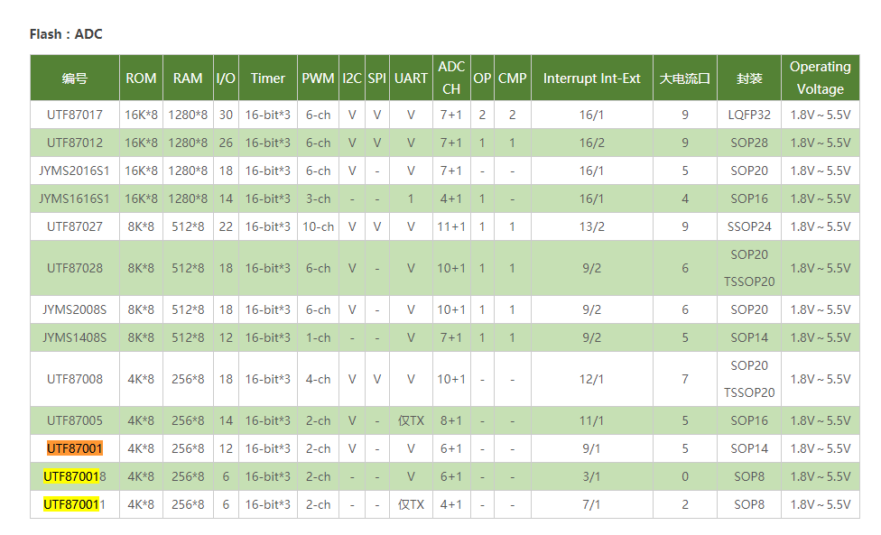
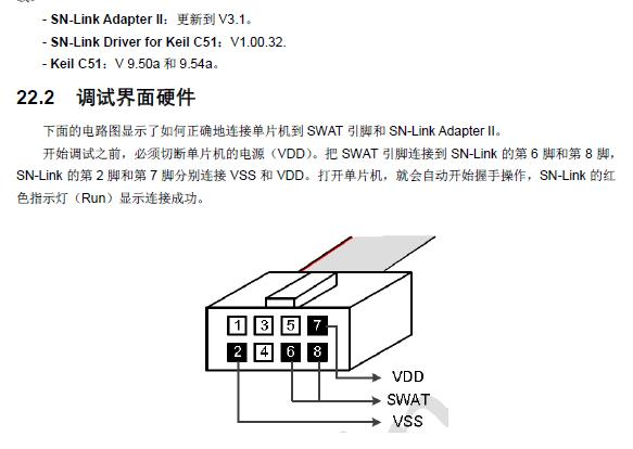
UTF87001, another microcontroller, manufactured by Songhan. I think it's in the C51 architecture. I have found very little information about it. It is programmed with some kind of SoniX SN-Link3 adapter.
 .
.
 .
.
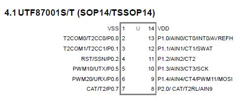
Pinout:
Programming information:
 .
.
 .
.
Alternative location for connector between plates:
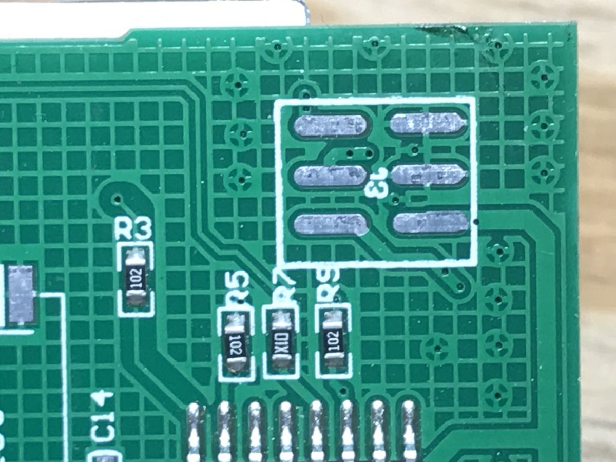
Alternative location for WiFi module (maybe these pads will come in handy if we solder wires to them?):
 .
.
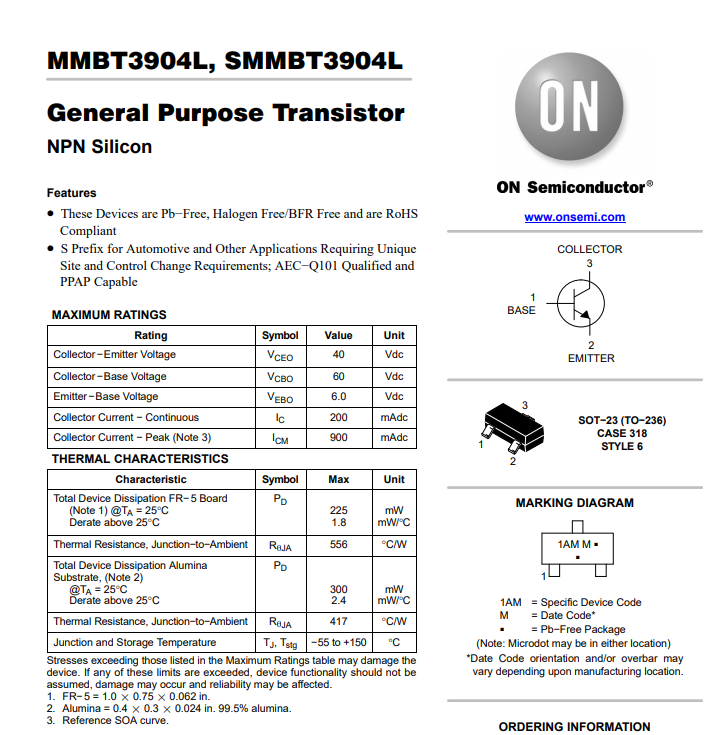
Transistor 1AM (to turn on the triac?).
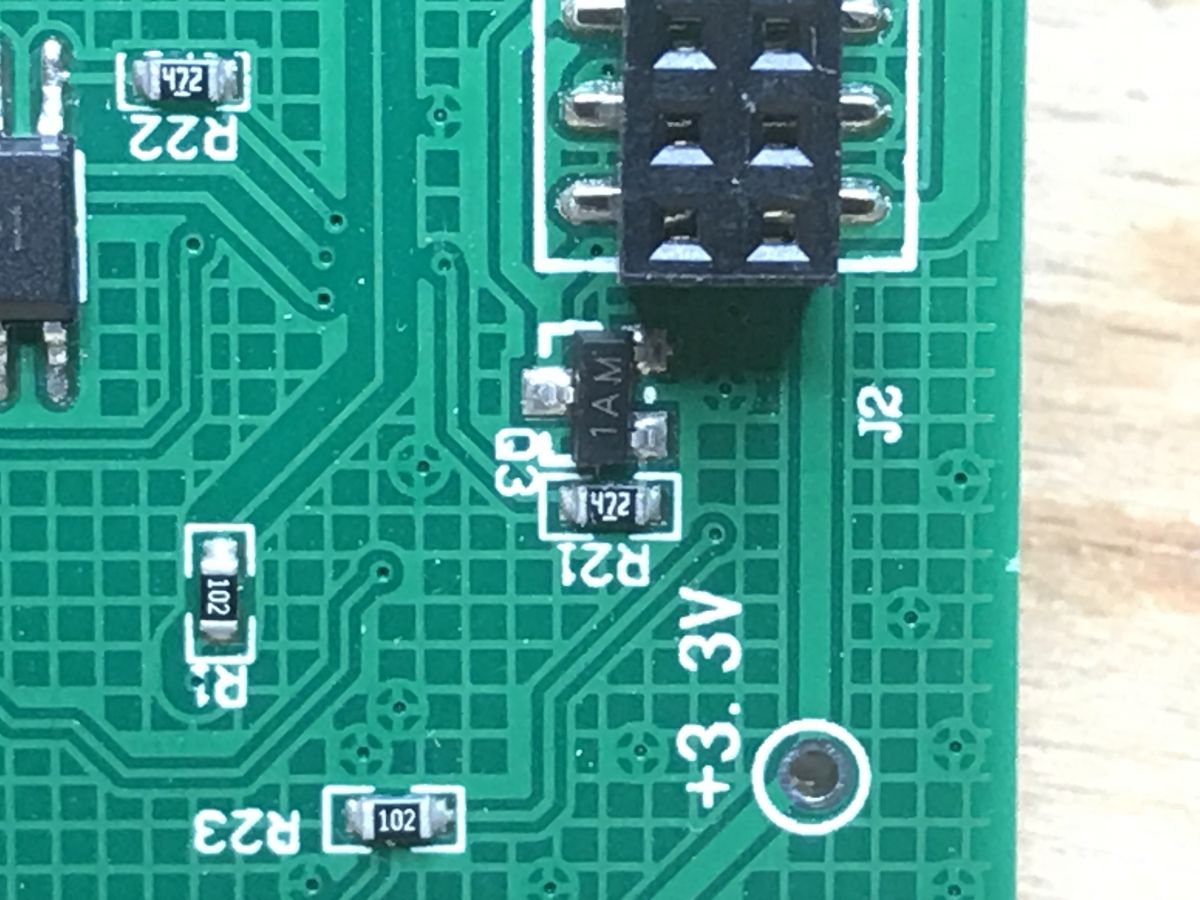 .
.
That is, MMBT3904LT1.
 .
.
Two useful soldering points:
 .
.
Next to the ESP is just the 26MHz clock generator (no separate memory for SPI as this is an ESP8285 with built-in Flash):
 .
.
Interior of dimmer - board with power supply and triac .
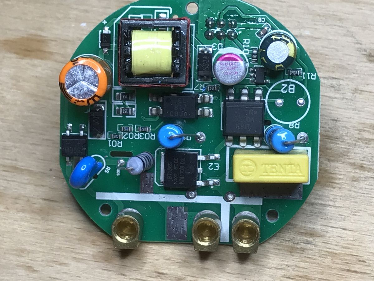
The circuits on this board are primarily for mains voltage:
 .
.
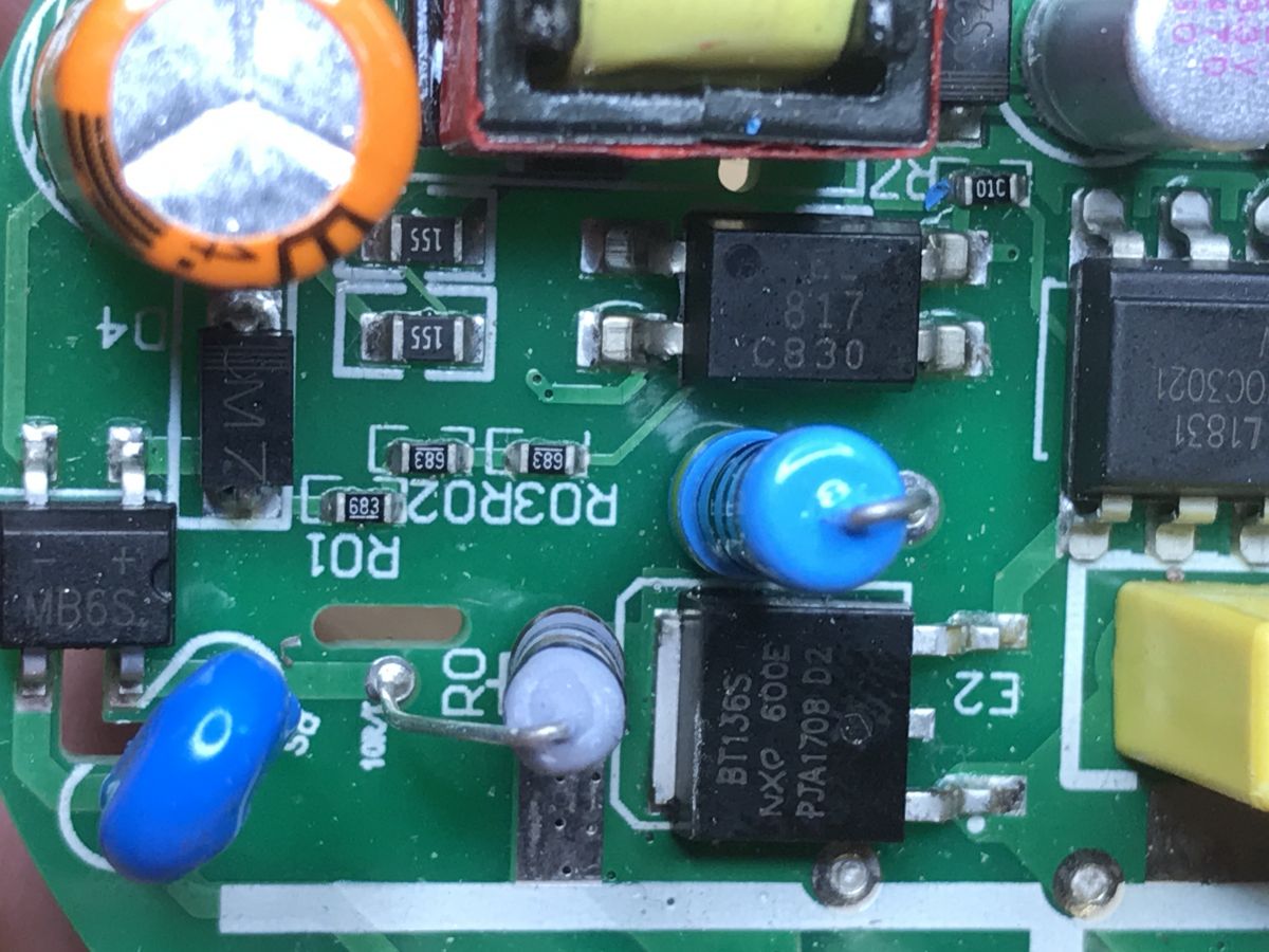
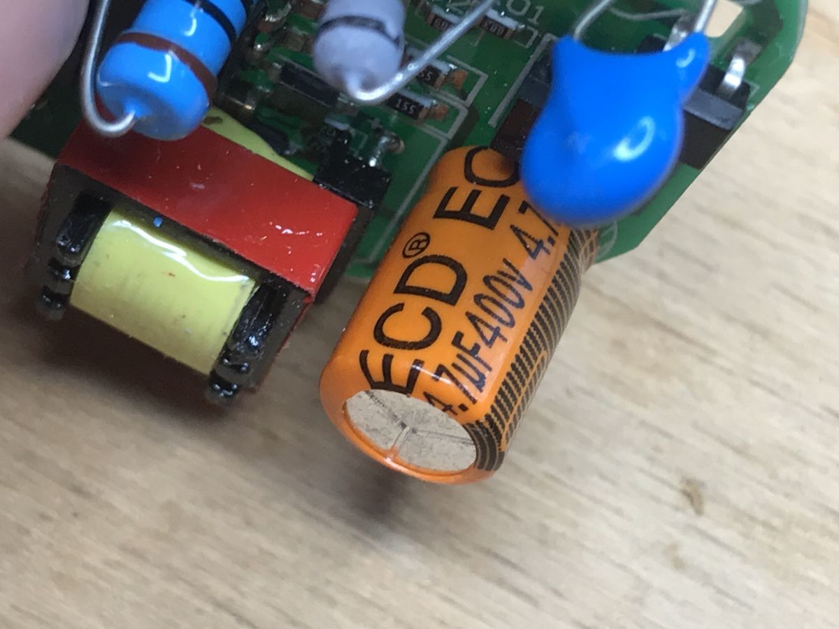
Fuse resistor, MB6S rectifier bridge, rather interesting path connection with resistors and rectifier diode:
 .
.
 .
.
The input is also protected by a varistor:
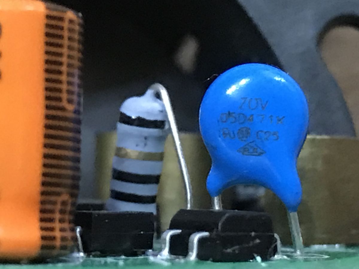
Varistor 05d471k, specification:
 .
.
I don't see any filters here, does this switch not sow interference?
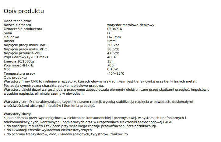
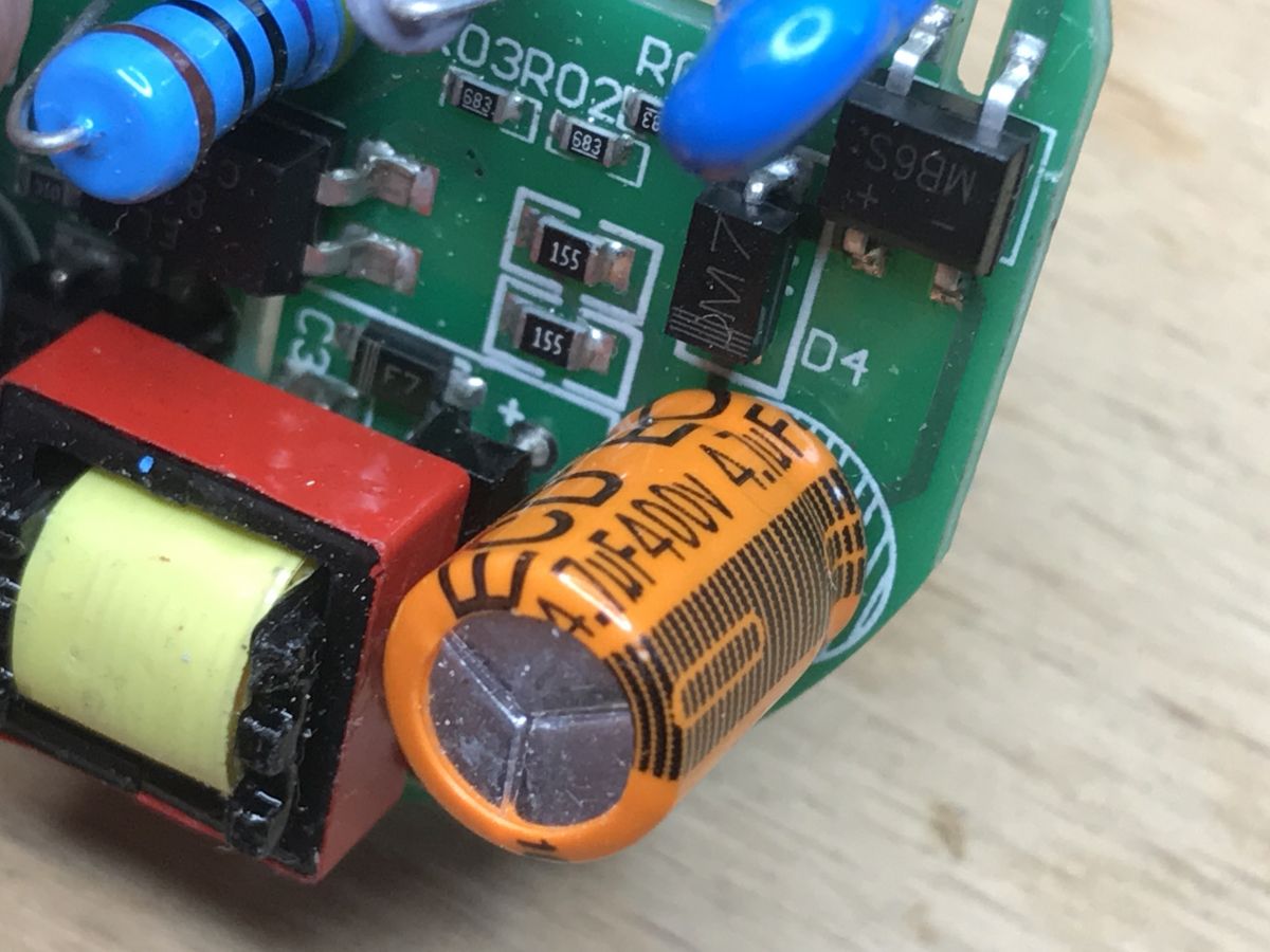
4.7uF 400V capacitor:
 .
.
This diode F7 is probably part of the snubber (gasifier) pin circuit from the power supply. The circuit itself that controls the power supply (including the built-in transistor, since it's a flyback) is under the transformer:
 .
.
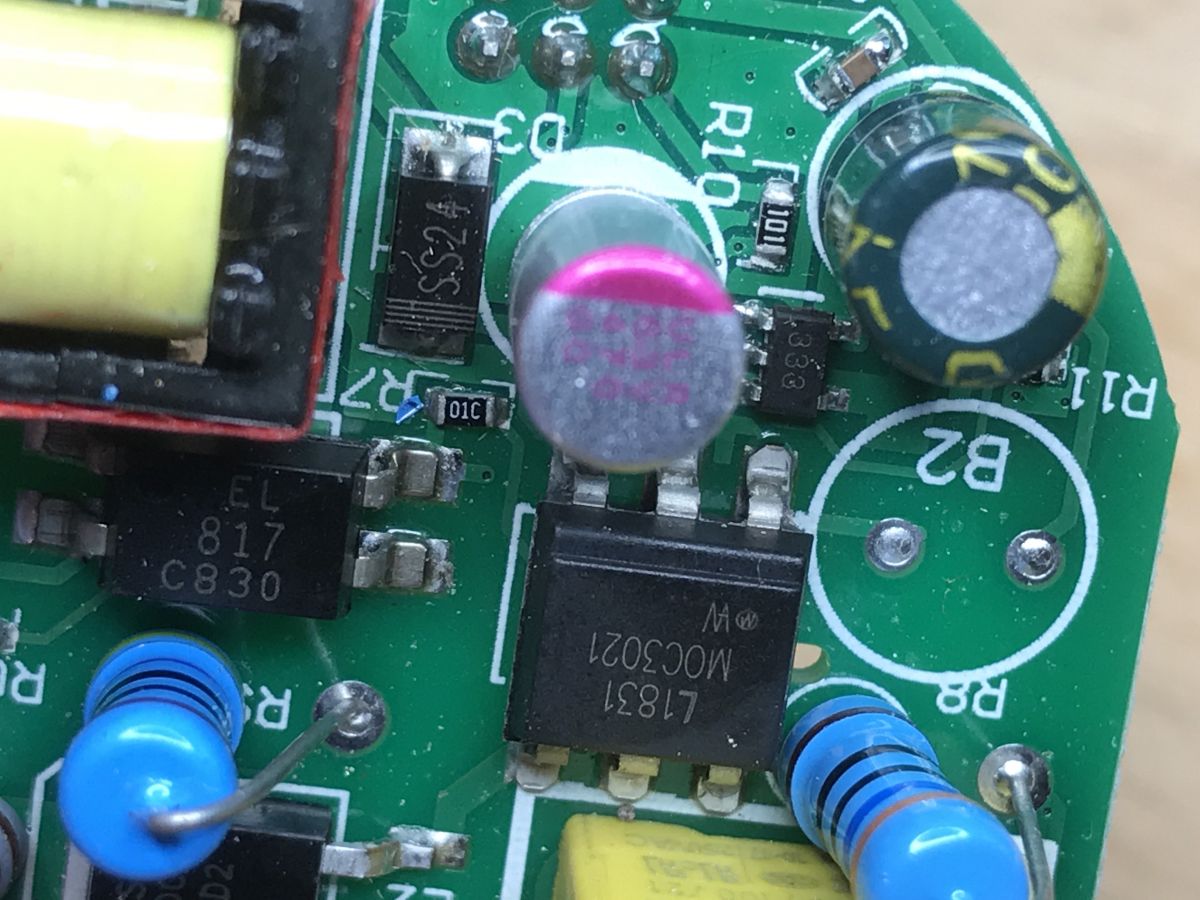
There is also a PC817 optocoupler (but it is not part of the power supply circuit, but is needed for dimming control):
 .
.
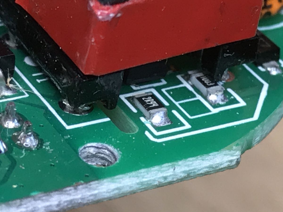
And on the other side is the triac with its driver.
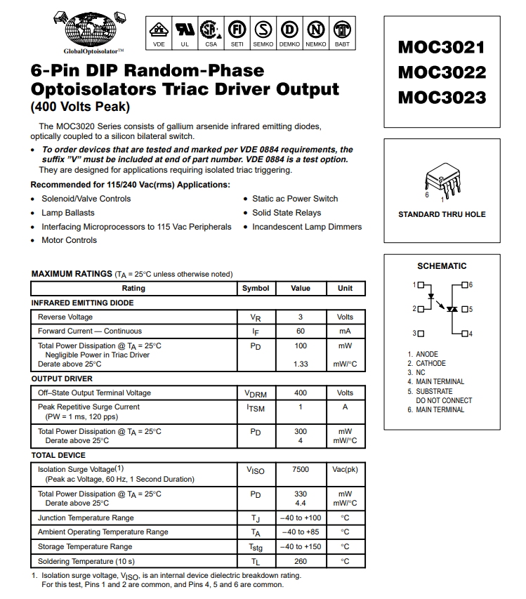
MOC3021 manufactured by Fairchild:
 .
.
 .
.
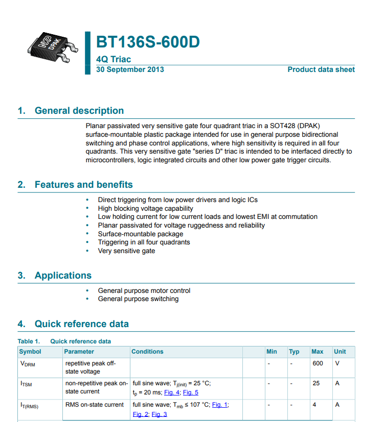
And the triac itself, BT136S-600E:
 .
.
 .
.
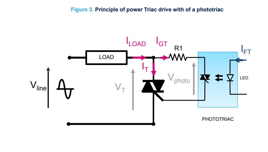
While we're here, we can take a look at the MOC3021 data note and explain its connection to the BT136S.
 .
.
Additionally, with the AN-780A:
 .
.
 .
.
A 360 ohm (2W) resistor here protects the optotriac from high current when switched on. A 470 ohm resistor (2W) and a 0.05uF capacitor (here: 0.047uF MKP X2 275V) reduces interference for the MOC3021.
Changed capacitors? Voltage measurements .
Already at this stage something didn't sit right with me.
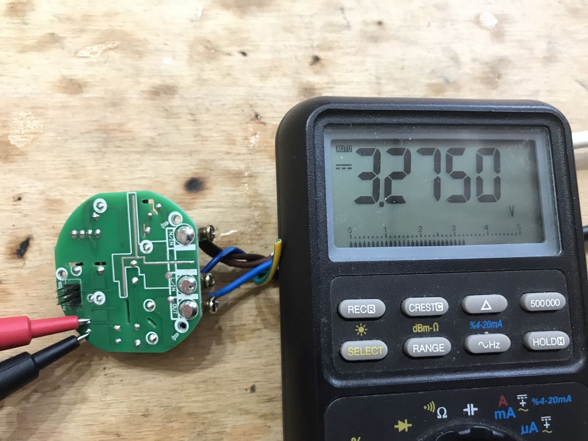
On the secondary side there are capacitors, consecutively a ULR "silver" at 6.3V with a capacity of 470uF, and then there is the usual electrolytic at 10V, also 470uF.
Shouldn't it be the other way around?
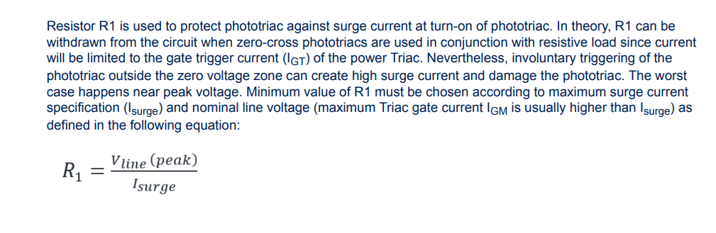
I have checked the voltages on them:

 .
.
Indeed, on the one at 6.3V there is just under 4V and behind the six legged circuit which is definitely an LDO or possibly a mini step down converter there is 3.3V (and a capacitor at 10V).
But I think I can see the rationale for this. ULR series:
 .
.
This is a low ESR capacitor, and the output of a flyback power supply should be just that. A bit low voltage, but probably still this one better than the usual electrolytic one that is further out. But maybe the Chinese guy got the wrong place?
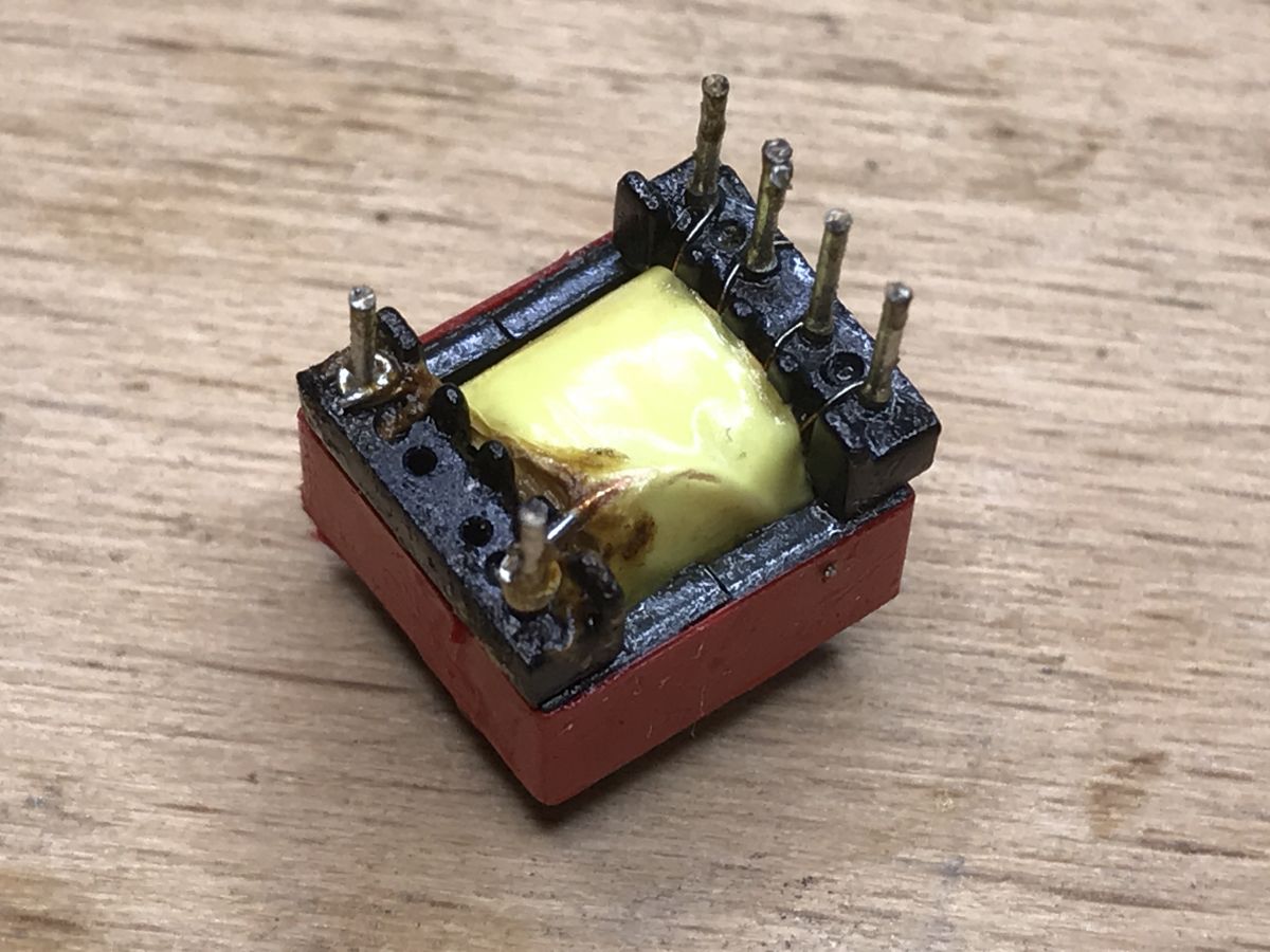
Further teardown - soldering out the transformer .
(chronologically I did this a bit later, but let the paragraph be here for clarity...) .
To fully understand (and later draw the schematic) I was still missing a few connections, so I decided to strip the board of the transformer, and then some other components too:
 .
.
 .
.
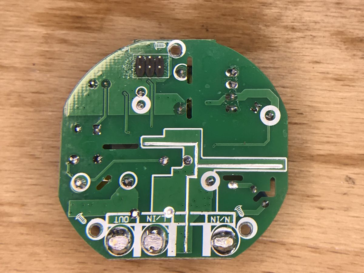
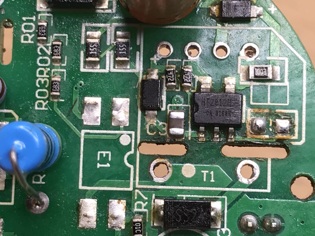
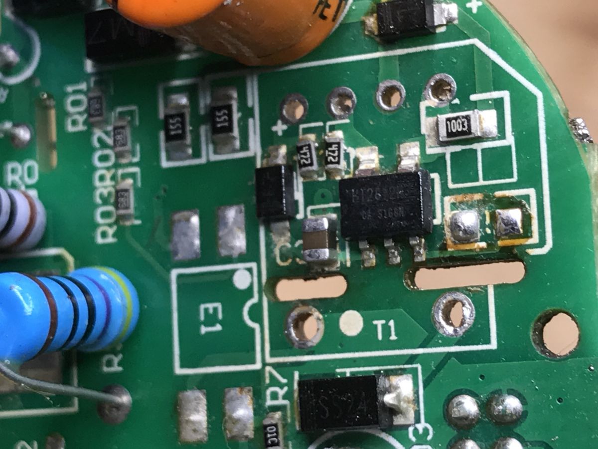
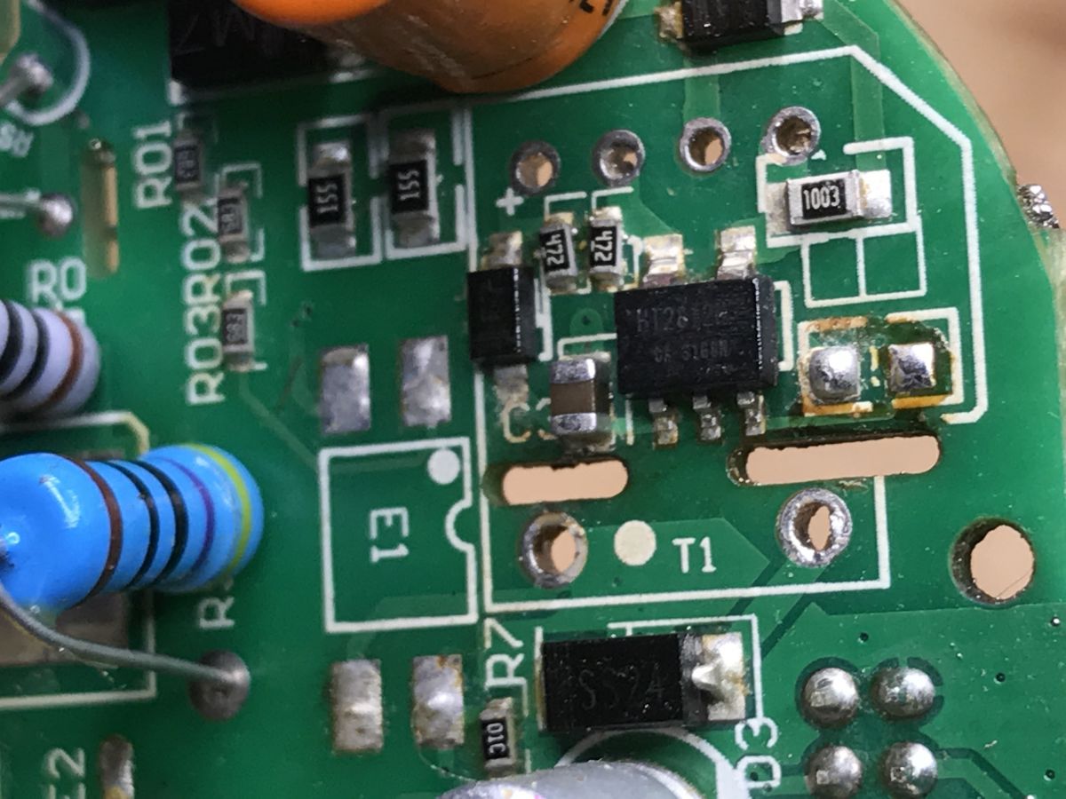
Bottom:
 .
.
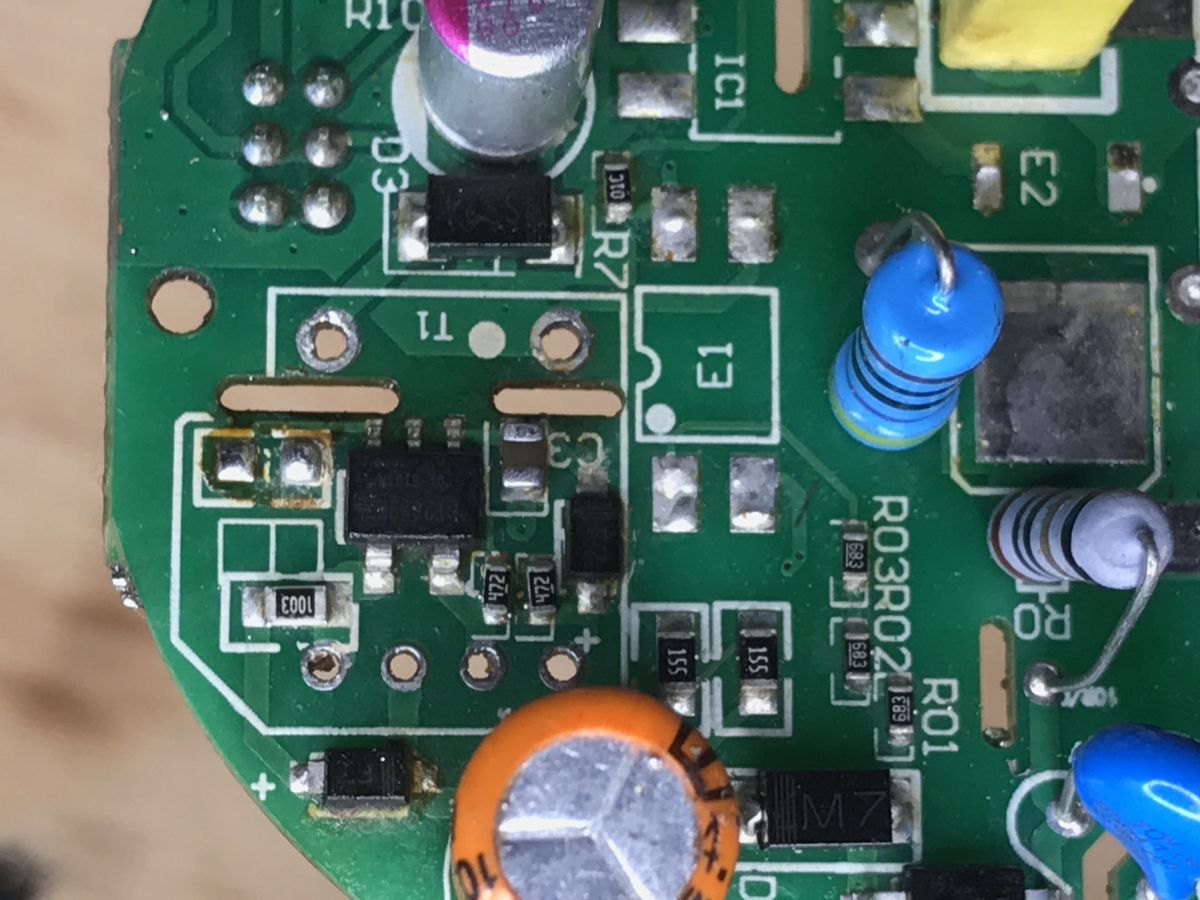
Top:
 .
.
The inverter controller is a HT2812H.
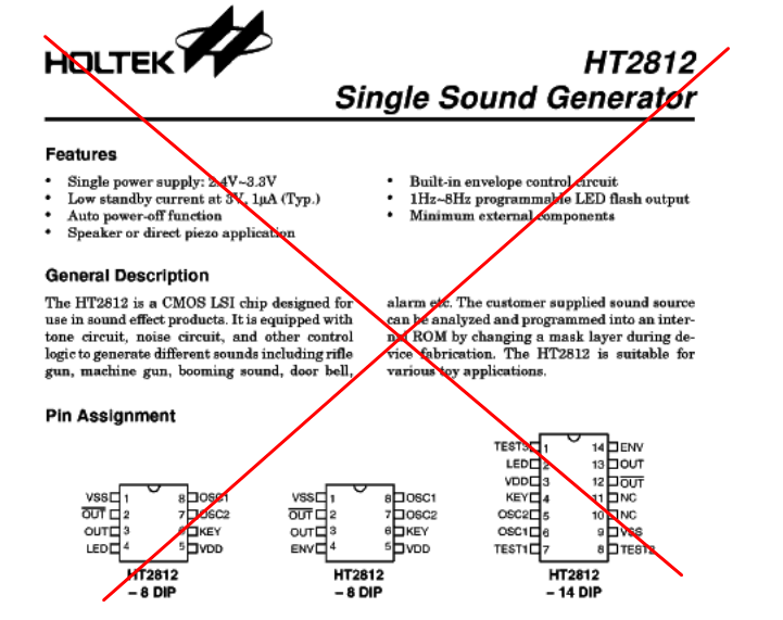
And here we have a strange situation - because there are two components with this name (ew without the H) on the net.
The tone generator from Holtek (it's not this chip):
 .
.
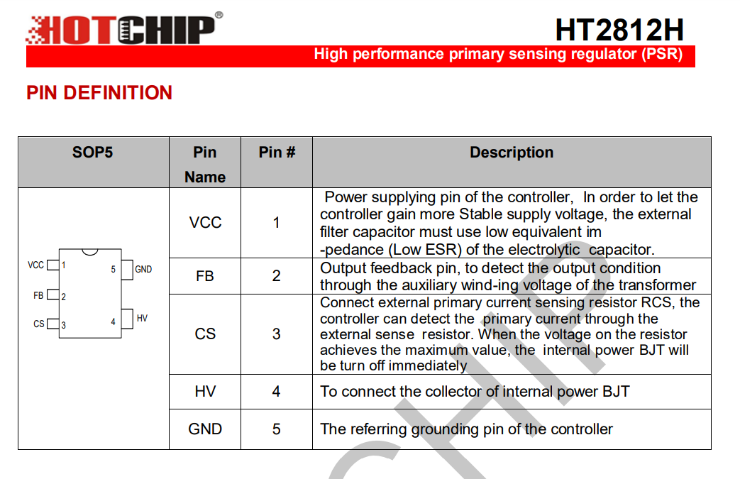
And an inverter controller from Hot Chip (it's this chip):
 .
.
The HT2812H is a "high performance primary sensing regulator" (abbreviated: PSR), the phrase "primary sensing" means that it takes coupling from the primary side, here from a resistor divider from the auxiliary winding (as opposed to taking coupling from the secondary side via an optocoupler)
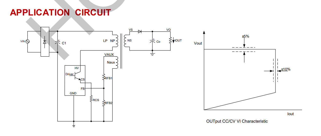
Here we have an example application of it (note that without the optocoupler, so this optocoupler on the PCB has a different role):
 .
.
and in a little more detail:
 .
.
And a pinout:
 .
.
First attempt at programming .
At first I thought just use the pads of free space on the TYWE3S or there ESP12, solder the wires there, UART RX TX and esptool.py will work:
 .
.
ESP12F pinout (pins also compatible with TYWE3S):
 .
.
I have discussed the programming procedure itself several times before, including here:
https://www.elektroda.pl/rtvforum/topic3749207.html
Unfortunately it did not work. Esptool.py was not even able to recognise the ESP.
A quick check of the connections with a multimeter explained why:
 .
.
The UTF87001 is connected to the ESP825 via the UART and probably communicates with it too. This makes it impossible to program the ESP. The UTF87001 would have to be soldered out.
And I will solder out the UTF87001 - but that's later.
Now it's time to check what is it that these chips are sending to each other?
You can use the connection I already have for this. UART does not give a rule that there must be only one RX for one TX. You can give two RXs to one TX and simply eavesdrop on the communication in this way.
Protocol - UART packets sent when touch buttons are pressed .
I started by checking what happens when we press the touch buttons. In this situation, UTF87001 is sending the data and ESP is responding.
After a few tries I guessed the baud - 19200.
 .
.
I have included the collected packets below. It is worth noting that the packets are separated by an ESC character (decimal 27), there is no CR LF:
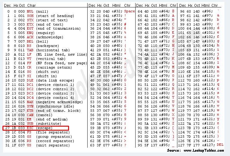 .
.
Pressing the middle button:
Code: C / C++
(the packages are separated only by the ESC character, in the above examples I have added transitions to new lines for readability) .
The format looks like JSON (without the brackets).
Pressing for longer (even up to reset mode) changes nothing:
Code: C / C++
Quickly pressing the dimmer button (until it is completely dark):
Code: C / C++
Responses (what the ESP sends):
Code: C / C++
Protocol - UART packets sent during control by the mobile app .
It is time to see what happens on the UART when we control the switch via eWeLink.
In this situation, the data exchange is initiated by ESP. ESP sends the following data to the UTF.
When we switch the lamp on/off:
Code: C / C++
When we change the brightness:
Code: C / C++
Just after power on:
 .
.
The implication is that apparently the ESP just mediates the communication and this strange microcontroller takes care of both the buttons and the brightness control.
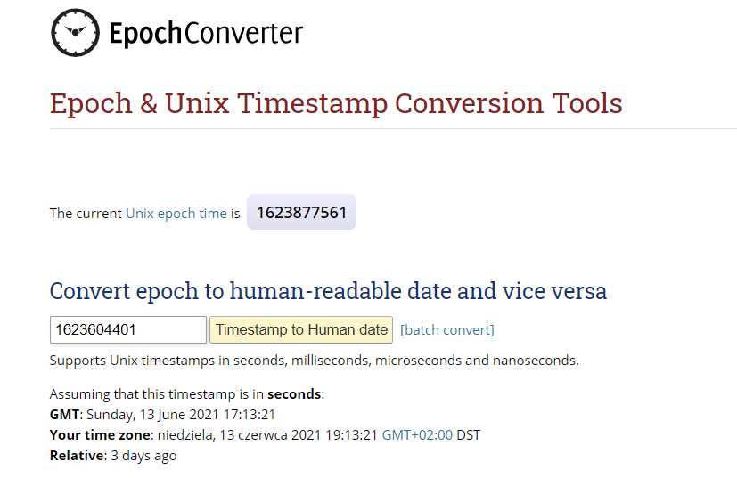
There is still a need to explain what the mysterious 1623604401 is.
When I see "1623", I immediately know what it is about.
This is the current time encoded in terms of the number of seconds that have elapsed since the beginning of 1970. This is known as epoch time, Unix time, POSIX time.
 .
.
source: https://www.epochconverter.com/
That's enough information for me.
Uploading the ESP batch .
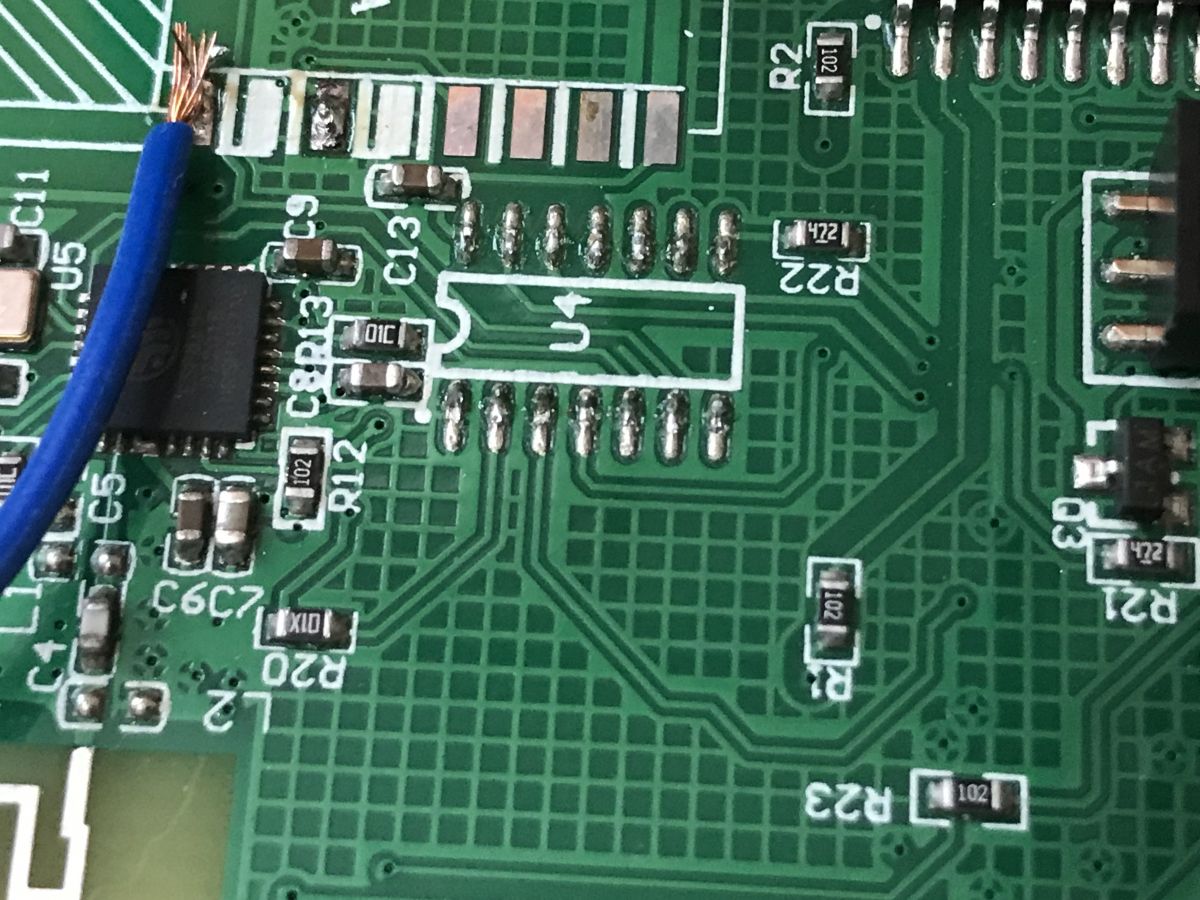
It was time to desolder the UTF87001, thus freeing up the UART lines and programming the ESP.
I used a cheap GJ-8018LCD pseudo "hot air" from China for this (it's generally flimsy, but it's lightweight and portable).
 .
.
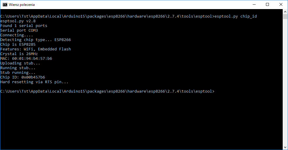
The programming started working straight away. Command esptool.py chip_id :
 .
.
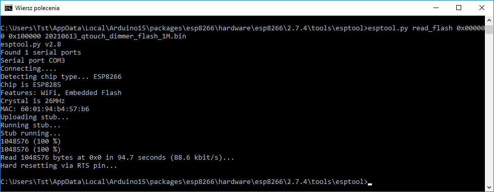
Flash ripping (flash backup):
esptool.py read_flash 0x0 0x100000 20210613_qtouch_dimmer_flash_1M.bin .
 .
.
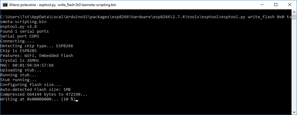
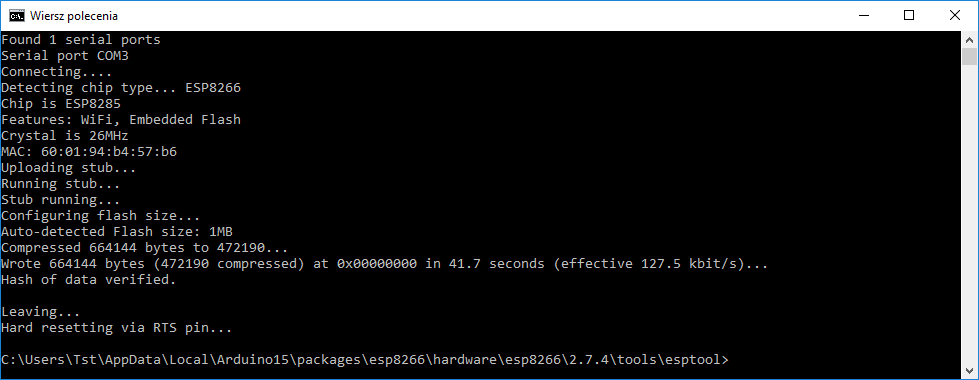
Flash upload.
esptool.py write_flash 0x0 tasmota-scripting.bin .
(I chose Tasmota-scripting to leave myself open to test their scripting system):
 .
.
 .
.
Tasmota uploaded, time to test the switch with Tasmota.
After uploading the batch .
The first thing I saw after uploading the batch and configuring WiFi for the Tasmota was that, surprisingly, the default setting was already working for the button and LED (that LED what flashes quickly when we are in pairing mode):
 .
.
Such as here:
https://tasmota.github.io/docs/devices/Sonoff-Basic/
So a configuration like this:
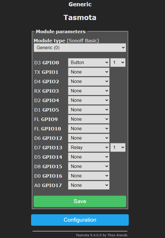 .
.
GPIO0 is the button and GPIO13 is the LED.
And the other thing I discovered is that the dimming buttons (the ones on the sides) still light up red and when pressed they light up blue, meaning ESP is not involved in their operation.
I decided to check everything with the bulb (after disconnecting the computer):
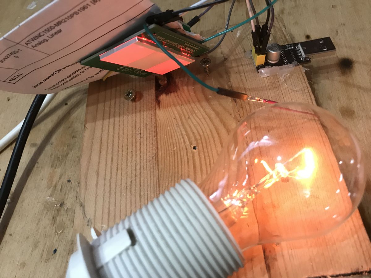 .
.
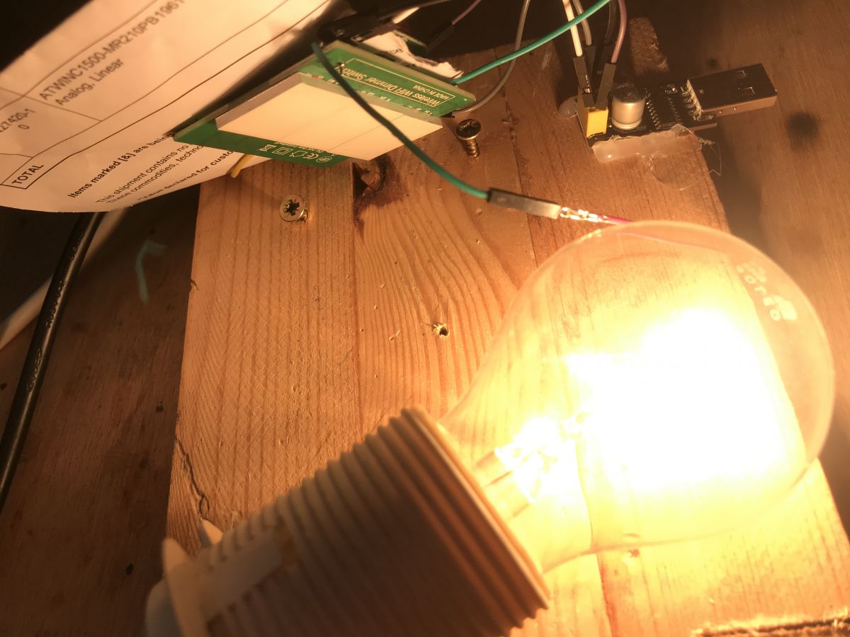 .
.
It quickly became apparent that even after uploading Tasmota to the ESP it continued to work:
- controlling the brightness of the bulb (when lit)
- switching the bulb on and off using the centre button
This confirms that these two operations are performed fully by the UTF chip.
The ESP, on the other hand, only controls the LED from the centre button and can also read its status, but cannot control the bulb directly.
That is, the centre button is connected to both the UTF and the ESP
(and this is logical, because ESP needs it to detect the pairing mode and UTF to switch the bulb on/off).
Trying to control from the serial port from the Tasmota console .
It would now be useful to put the knowledge gathered into practice and try to posterise the UTF87001 chip via ESP.
Tasmota supports the so-called Serial Bridge:
https://tasmota.github.io/docs/Commands/#serial-bridge
It is operated from the Tasmota console.
In theory, all you need to do is type:
seriallog  0
Baudrate 19200
SerialDelimiter 27
And that should be enough to handle the UART, then you send with the SerialSend command (or versions of it - there are separate ones for hex, etc).
Plus the command:
SetOption22
should return "On".
Unfortunately with me it didn't want to work the first time. I had to switch the seriallog on and off several times to get the UART to start receiving:
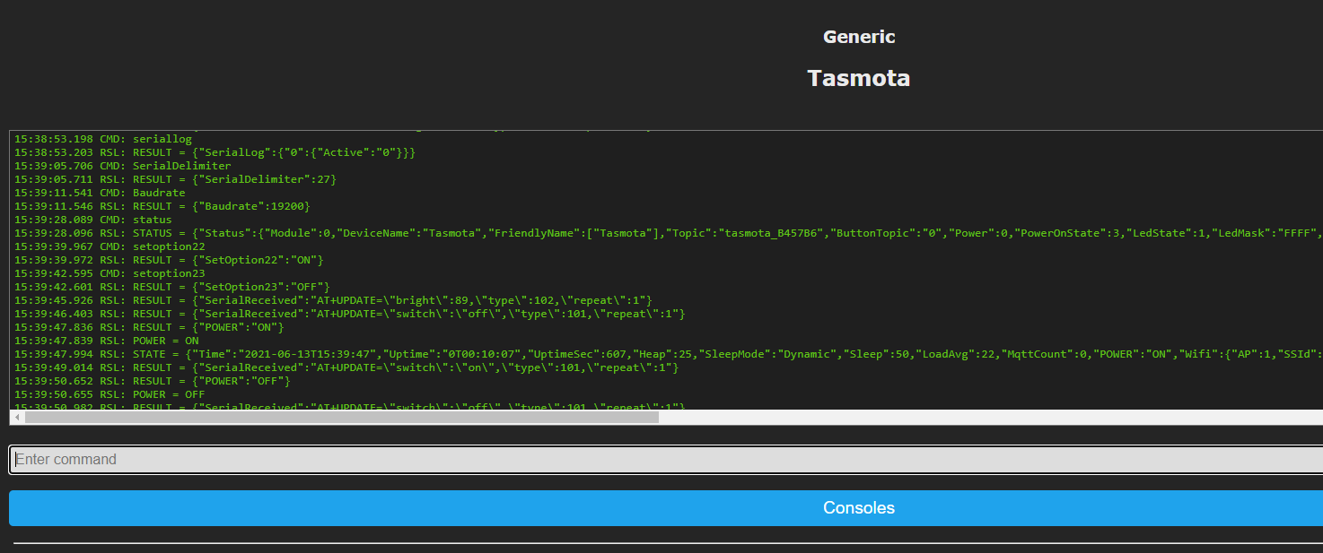 .
.
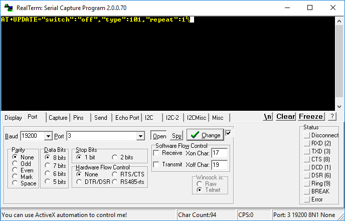
You can see that the Tasmota is receiving AT+UPDATE commands from the UTF87001 (Serial Received events appear), both brightness and switch.
Now, it would be possible to send commands to the UTF87001 from within Tasmota but unfortunately this would rather already require implementing support for this in C, or possibly in this simple Tasmota scripting language....
Confirmation of protocol operation .
Tasmota does not natively support this communication protocol with UTF87001, so I decided to test just yet its operation on the Arduino. NOTE: You should not connect the Arduino UNO directly to the ESP as the Arduino has 5V logic levels and the ESP has 3.3V and is not officially 5V-tolerant. (Although I will admit that there are often opinions that a one-off such connection won't hurt).
The Arduino will send commands to UTF8700 instead of ESP.
I have therefore prepared the code:
Code: C / C++
And I hooked it up to the switch, powered from a powerbank (not mine!) of course:
Success!
At this moment I don't know if this AT+START is needed at all, maybe not, but the code above definitely works and allows you to control the UTF87001 via the UART.
A few tidbits from the original QTouch batch .
Before uploading the Tasmota, I backed up the original ESP batch from this switch. The batch is, of course, in binary form, compiled, and you'd need the right tools to decompile it (although I think I might be able to present that in another topic), but you can still try to review it even in notepad to look for text constants that are readable to you.
For example:
error HTTP/1.1 101 Switching Protocols action params reason config hb hbInterval regInterval IP port cmd upgrade redirect notify sledOnline off GET /api/ws HTTP/1.1
Host: iotgo.iteadstudio.com
Connection: upgrade
Upgrade: websocket
Sec-WebSocket-Key: ITEADTmobiM0x1DabcEsnw==
Sec-WebSocket-Version: 13
Invalid owner uuid iotgo_tree_register iotgo_tree_date AT+SEND=fail AT+SEND=ok version romVersion model ts GET /device HTTP/1.1 POST /ap HTTP/1.1 { } ssid password serverName id_to_app %d HTTP/1.1 200 OK
Content-Type: application/json
Connection: keep-alive
Content-Length: {"error":0} {"error":400,"reason":"timeout"} {"error":401,"reason":"Wrong password"} {"error":402,"reason":"No AP found"} {"error":403,"reason":"Connect failed"} {"error":404,"reason":"Unknown exception"} accept post " tţ?%02x OK
Above we see snippets of HTTP requests sent to/through the API. Including the interesting URL iotgo.iteadstudio.com.
By the way, you can type these ITEADTmobiM0x1DabcEsnw into Google and get:
https://github.com/vponomarev/Sonoff-Server/blob/master/doc/ServerExchange.log.txt
AT+SIGNAL= AT+CONF_LIST= , ERROR
AT+START
AT+DEVID?
AT+DEVID= AT+DEVMAC?
MAC: - AT+VER
FWTRX-TA85 AT+SHA256
OK
AT+GPIO_LOW
AT+GPIO_HIGH
AT+WIFI
AT+END
AT+SEND= >
LENGTH ERROR
AT+READ_CONF= AT+TRANSSEND= AT+FWVER?
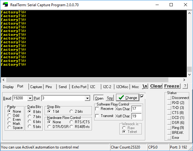
AT+FWVER= ITEAD_PD_T 27955416 AT+CWJAP= AT+GPIO_IN= AT+GPIO_OUT= AT+GPIO_READ= AT+GPIO_LOW= AT+GPIO_HIGH= AT+SETBAUD= AT+TRANSREV_ON AT+TRANSREV_OFF enabled type do startDo endDo once repeat duration * factory! factory? factory?
Above you can see the commands of the AT batch that this ESP originally has uploaded.
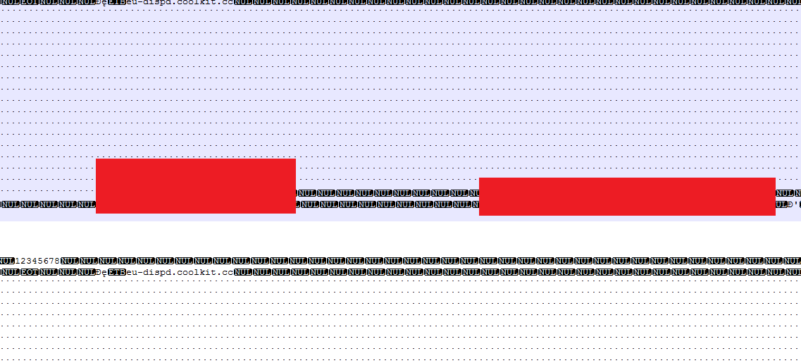 .
.
And here above we see (censored!) the password and SSID of my WiFi network , written of course as plaintext, i.e. plain text, without any attempt at masking.
They could have at least done a simple XOR on this character string to mask it from the simplest search, but as you can see they deemed it unnecessary.
For this reason I will not publish this batch here. Readers should also be aware that by throwing away the Smart device they may unknowingly be making their WiFi password public....
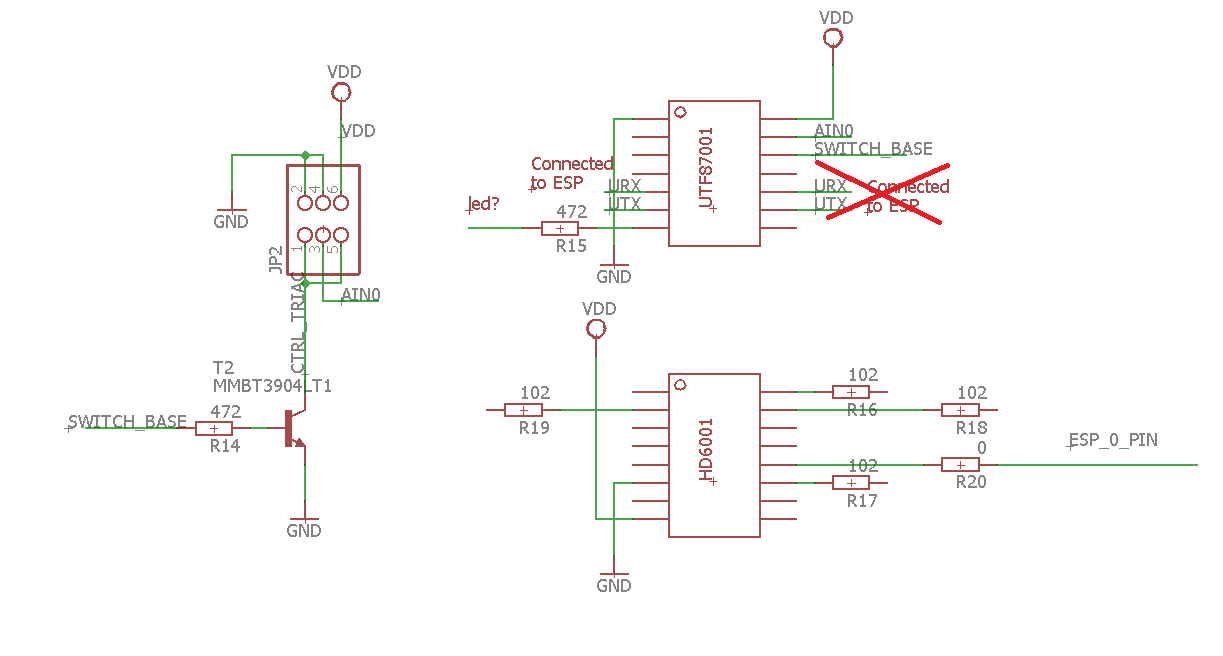
QTouch dimmer schematic .
Finally, it is time to gather is all the information gained into one place and present a sketch of the product diagram.
The schematic is not complete, I have drawn as much as I needed to understand the operation of the product.
The resistor values in the schematic are given in SMD codes, i.e. 472 means 4.7kΩ (unless otherwise written)
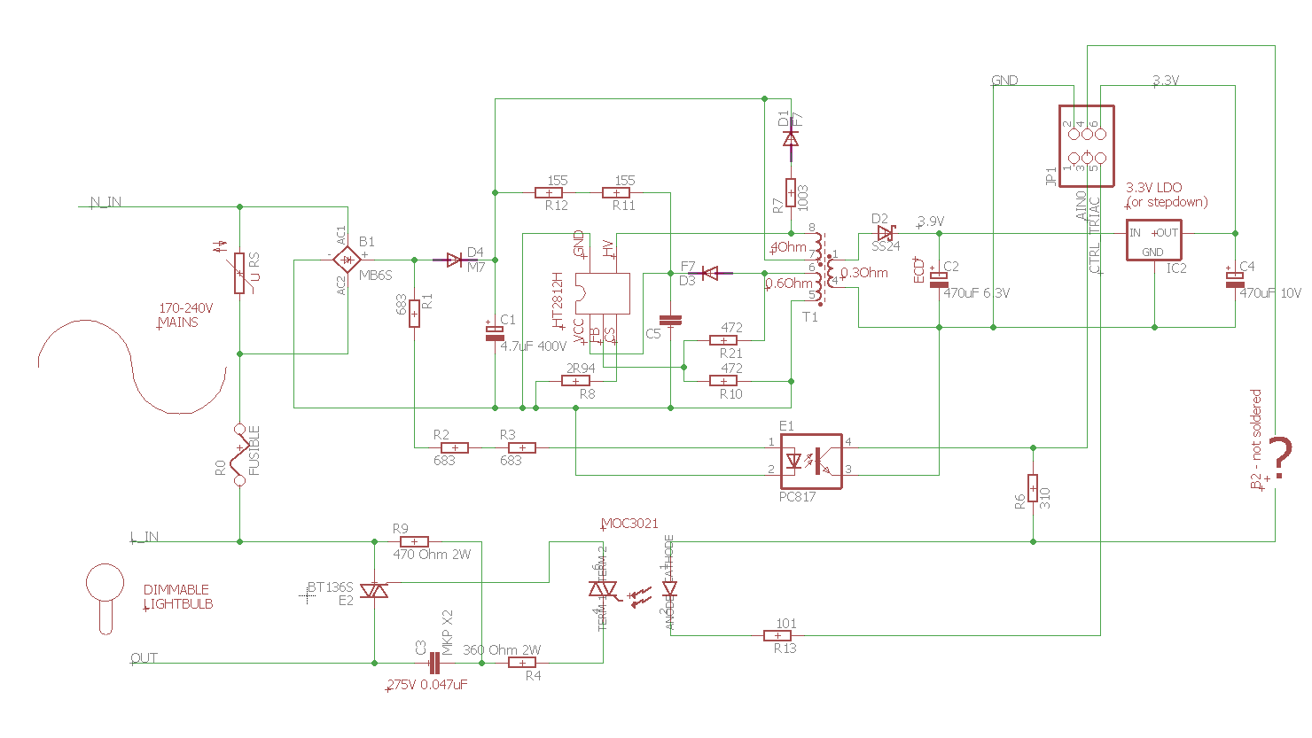 .
.
PCB with ESP (schematic after correction 2021-06-22):
 .
.
Explanation of the role of the components.
Input protection: .
- here we have varistor RS (name from the board)
- and fuse resistor R0
- other filters are missing
Power supply block: .
- MB6S, you know, rectifier bridge
- between rectifying bridge and electrolytic capacitor C1 there is additionally rectifying diode D4, not without a reason, it is for the optocoupler (more on that shortly)
- the power supply is implemented on a HT2812H in flyback topology
- R8, with a value of less than 5 ohms, is a shunt, on which the HT2812H performs current measurement (pin CS - Current Sense)
- R21 and R10 of 472 (4.7k ohms) form a resistor divider, for feedback, on it the HT2812H measures the voltage on the auxiliary winding via pin FB (Feedback)
- high-speed diode F7 charges C5 from the auxiliary winding, the capacitor supplying the HT2812H via its VCC pin
- at the start of circuit operation C5 is charged directly from 325V via R12 and R11 (smd codes 155, i.e. 1.5M ohms)
- D1 fast and R7 are the snubber (gasifier) pins on the primary winding
Block of optocoupler: .
- the optocoupler is needed for the microcontroller to know when the rectified sine wave is rising (to be able to adjust the brightness and switch on the triac), it is not needed for the power supply (because usually when someone sees the optocoupler they think that the power supply takes the voltage regulation from the secondary side)
- diode D4 is placed after the Greatz bridge so that the current from the electrolytic capacitor does not "go back", because we want a sine wave to go to the optocoupler (or rather its halves already rectified by the bridge)
- the optocoupler feeds the signal to pin AIN0 from UTF87001 on the second board
Block of the triac:
- the triac is a BT136S, controlled by a MOC3021, an optotriac, it also provides isolation
- a large 2W, 470 ohm resistor protects the optotriac from high current when switched on (see AN780 for details)
- a large 2W, 360 ohm resistor and capacitor C3 MKP X2 at the triac act as snubber, the diagram is according to the MOC3021 data sheet
- The MOC3021 is controlled via transistor 3904 located on the second board, via UTF87001
Block ESP/microcontroller (shown residually on the schematic)
- The ESP8285 including hardware (omitted from the schematic) and antenna on the PCB from path
- UTF87001 handles dimming, on, off, communicates with ESP over UART
- HD6001 handles touch buttons
- ESP8285 only reads the status of the main button to enter the RESET state, only controls the pairing status LED and communicates with the UTF87001 over the UART
- the middle touch button is shared by ESP and UTF, both read its state
- there is no RF433 chip on the board (there is not even a place for it), there is no PCB antenna from RF433, there is no buzzer from RF433, RF433 is definitely not supported
Summary .
I have not yet encountered such confusion and misinformation with Smart products, although I have ordered many from China.
Admittedly, this product here was from a Polish seller, but it is clear that it is still "made in china".
The QBP.DIM.WIFI product came to me in a box suggesting that it supported RF433MHz remote control, when in fact it did not support it at all (you can tell by the lack of an RF antenna, by the lack of a buzzer from the RF pairing signal and by the lack of an integrated circuit which can support RF).
The instructions inside, on the other hand, showed the connection of a different switch (a different switch; the one that plugs into the L wire and does not need to be connected to the N wire; from here you need to connect both wires).
The packaging also included a capacitor (called an "adapter") which is not necessary here and is also misleading.
The seller and the description from the offer additionally suggested that this switch is used behind a transformer (?!) on low voltage and not on mains voltage, which was also not true.
The switch itself also probably makes quite a bit of noise on the mains (comments from other buyers confirm this), there are no filters on the input, good that they at least gave a fuse resistor and varistor.
The design of this switch itself is quite interesting, but very unfriendly to DIY/Tasmota/Home Assistant, because it is difficult to upload a new batch to the ESP (you have to desolder another chip) and just uploading the batch won't give you much, because to control anything you would have to implement UART commands...
Which is a shame, because aesthetically I like this switch.
PS: It's possible that I'll try to pull the project further and add support for this switch to Tasmota, it may work out fully through its scripts, but that remains to be seen.
In the appendices I give the component datasheets from the middle and in addition the datasheets of some similar PSR inverter controllers.

p.kaczmarek2 wrote 14637 posts with
rating 12649 , helped 655 times.
Been with us since 2014 year.
Comments
Very nice and comprehensive description (as usual from @p.kaczmarek2 ). The schematic shows URX and UTX in UTF87001 in the wrong place (they are on the other side). Maybe you can "inactivate" UTF87001... [Read more]