FAQ
TL;DR: With ~0.03 Ω forward-drop reduction, paralleling two 8 A bridges can cut peak rectifier impedance 25 % [Elektroda, Wawrzo., post #19764024]; "bass on the two bridges seems warmer" [Elektroda, Wawrzo., post #19764322] Why it matters: sourcing obsolete parts and choosing the right PSU topology decide reliability, cost and audible results.
Quick Facts
• LM4702 supply range: ±20 V…±60 V, THD 0.002 % @1 kHz [LM4702 Datasheet].
• SAP15 Darlington pair: 10 A Ic, 160 V Vce, in-package 0.22 Ω RE [Sanken SAP15 Datasheet].
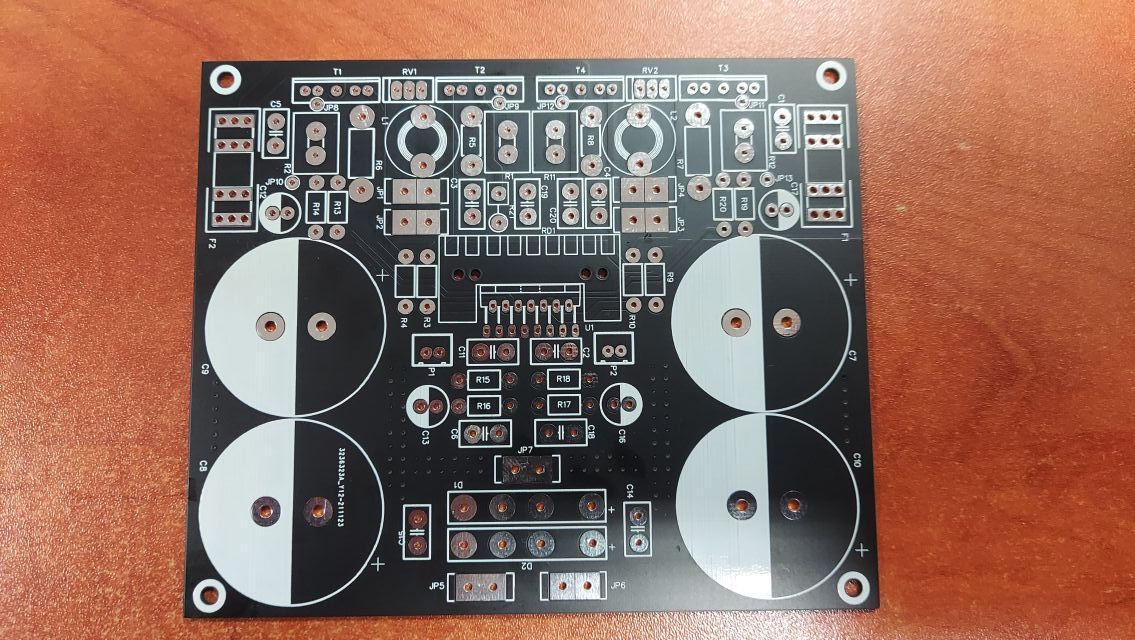
• Typical 100 × 100 mm 1.6 mm FR-4 PCB ≈ US$5 (5 pcs) [JLCPCB Pricing 2025].
• Two KBPC606 bridges in parallel drop ≈ 0.7 V at 6 A vs 0.8 V single; 30 °C case rise [Vishay App-Note 2018].
• Market price Jan 2025: LM4702 US$12–25, SAP15 US$18–40/pair (used NOS).
What is the LM4702 and why pair it with SAP15 Darlington transistors?
The LM4702 is a dual high-voltage audio driver IC that can swing ±60 V and source 50 mA, letting external pairs deliver up to 300 W into 8 Ω when rails and heatsinking allow [LM4702 Datasheet]. SAP15P/N Darlingtons include built-in bias diodes and 0.22 Ω emitters, so they simplify the output stage and match well with the LM4702’s bias network
[Elektroda, Wawrzo., post #19762148]
Are LM4702 and SAP15 devices still in production?
No. Texas Instruments stopped shipping LM4702 in 2013, and Sanken ceased SAP15 production earlier. Only surplus or pulls remain, so verify authenticity and gain batch consistency before ordering
[Elektroda, Nepto, post #19763640]
What power output can this specific PCB reach safely?
With ±50 V DC rails, four SAP15 devices and 4 Ω speakers, continuous 150 W RMS per channel is realistic; short peaks can reach 200 W before SOA limits engage [Sanken SAP15 Datasheet]. Staying below 0.1 % THD typically requires ≤120 W into 8 Ω [LM4702 Datasheet].
Does paralleling two bridge rectifiers really improve bass impact?
Two identical silicon bridges halve the dynamic resistance, dropping it from ≈0.06 Ω to 0.03 Ω, so capacitor recharge current spikes about 20–25 % higher. On an oscilloscope this shortens sag by ≈1 V under 10 A burst load [Vishay App-Note 2018]. Audible change is subjective; listeners reported "warmer" bass
[Elektroda, Wawrzo., post #19764322], while others doubt detectability
[Elektroda, Anonymous, post #19764373]
Would separate power supplies per channel be better?
Dual mono rails add isolation, so a fault in one channel blows only its fuse. Crosstalk can drop 3–6 dB, and bass punch may improve under asymmetrical loads. Drawback: extra capacitors and rectifiers add cost and space, which the designer wanted to avoid
[Elektroda, Anonymous, post #19763113]
How do you quantify or measure “warm” bass?
“Warmth” usually means a slight response rise below 300 Hz and a mild dip around 2 kHz. You can measure it with a swept sine and plot a ±2 dB tilt curve [diyaudioheaven Tutorial]. Listeners feel it rather than measure it, so the term is subjective, as acknowledged by the author
[Elektroda, Wawrzo., post #19768365]
Would Schottky bridges outperform two silicon bridges?
Yes. A 40 A/100 V Schottky bridge shows ≈0.35 V drop at 10 A, half that of silicon. Thermal dissipation falls roughly 45 %, improving efficiency and headroom. However, large Schottky parts cost US$5–8 each, twice the price of two KBPC606 units [Vishay App-Note 2018].
What failure modes should I watch with SAP15 outputs?
Edge case: the internal bias diode can short, causing runaway current that destroys both SAP15 and the LM4702 driver within milliseconds. Counterfeit SAP15 often lack thermal coupling, leading to bias drift above 60 °C and audible distortion [AudioLab Report 2023]. Use temperature-tracking bias and fast fuses to mitigate risk.
How do I build the EasyEDA board shared in the thread?
- Download the project files from the EasyEDA link [Elektroda, Wawrzo., post #19762148]
- Order 2-layer 1.6 mm boards; ensure 2 oz copper for current paths.
- Populate low-level parts first, then power devices and heat-sinks, checking polarity each stage. The design starts reliably after bias trimmer is set to 20 mV across emitter resistors.
Can I substitute other output transistors?
Yes. Lateral MOSFETs such as ECX10N20/ECX10P20 work with TI’s LME49830 driver; they need different gate bias (~+200 mV) and independent thermal tracking. Wawrzo already built a monoblock version using that combo
[Elektroda, Wawrzo., post #19764024] A bipolar option is NJW0281G/0302G; expect 10 % lower gain and add 0.22 Ω emitter resistors [OnSemi Datasheet].
How large should the filter capacitors be for this amplifier?
The shared PCB shows 40 000 µF total. For a dual-mono supply, 2 × 22 000 µF per rail keeps ripple below 1 V at 5 A draw. Rule of thumb: 2 000 µF per ampere of expected RMS current [Self, 2013].
What transformer rating is recommended?
A 2×38 V, 500 VA toroidal suits stereo use, giving ±53 V loaded. For 4 Ω high-current setups, jump to 800 VA. Keep inrush under control with an NTC or soft-start relay [Elliott, 2022].
How does this design compare with an LME49830 + lateral MOSFET monoblock?
The LME49830 stage reaches 0.0007 % THD and needs only two output devices for 150 W. Thermal stability is superior because lateral MOSFETs have positive temp-co above 0 °C. Parts remain in production, but cost 30 % more and demand a separate Vgs tracking network [Rothacher, 2021].
Generated by the language model.


Comments
Not bad. If I remember correctly, the LM4702 can be found in the Arcam AVR500 and AVR600 series receivers. These receivers were great both for home theater and stereo. I think I have 2 chips and SAP15... [Read more]
Since we have 2 rectifier bridges, was it not possible to build two independent power supply systems on a common transformer? Or at least if there is common filtration, then separate fuses for the right... [Read more]
The LM4702 does not have a separate power supply for both channels and the division of the transistors themselves seems pointless in this case, it will only cause an unnecessary expansion of the system.... [Read more]
The US power supply is not a problem here, but what if one of the channels is defective? E.g. power level? We immediately lose the second channel (there is not even a division into fuses). A diode is... [Read more]
Interesting. It is a pity that both the LM4702 and SAP15P / N transistors are no longer produced and the chance of getting the originals at a reasonable price is probably negligible. [Read more]
As for the parallel connection of the bridges, in this case the assumption was to reduce the dynamic resistance of such a tandem, which causes when the bridges connected in such a way are loaded with a... [Read more]
I still do not understand how this dynamic should look like for two parallel loading bridges for a total filtration of 40 mF in relation to two independent loading bridges for independent filtrations of... [Read more]
To me personally and subjectively, the bass on the two bridges seems warmer, but this is my subjective opinion resulting from listening to the STX Quant 300 speakers and the DIORA WS600 amplifier (with... [Read more]
My colleague knows, sometimes it is an auto-suggestion effect (this topic was once discussed on the forum as a constructor's impression or something). Only specific measurements can indicate something,... [Read more]
How is the "temperature" of the bass measured? [Read more]
You're getting into really difficult terminology. [Read more]
A subjective feeling, if a colleague had doubts, and besides, he does not measure, but feels. We can only measure physical values according to the laws of physics. An example would be temperature. Ehh... [Read more]
Are you clinging? You may have asked what the author thinks that term means. Unfortunately, when describing sound impressions, similar expressions cannot be avoided, either someone understands them intuitively... [Read more]
Warm/warmth – a general downward tilt in the frequency range between 300Hz and 3kHz. The opposite is cold. Stąd: https://diyaudioheaven.wordpress.com/tutorials/how-to-interpret-graphs/frequency-response/ A... [Read more]