Hi.
I made a power supply, nothing innovative because it is a good construction that has been going through the internet for over a dozen years.

With this construction, I put more emphasis on the design (at least I think so). Despite quite a long thought process, this power supply was not without mistakes. Fortunately, these errors do not force any major changes, such as cutting paths, etc.
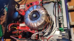
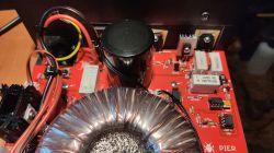
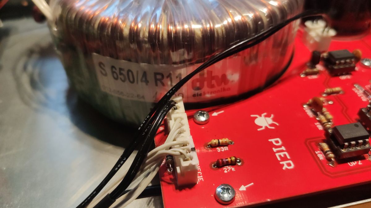
It started with the fact that I fell into my hands ups and in it quite a large transformer, 2x15V ~ with power
I guess 650W. Additionally, it has a 22V ~ winding used for an auxiliary power supply. Designation of the transformer S 650/4 R11.
As I had no idea where to use it, it fell on the power supply, there are never too many of these. I had no experience with other designs, so I focused on the Electronic Lab.
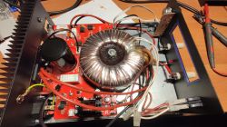
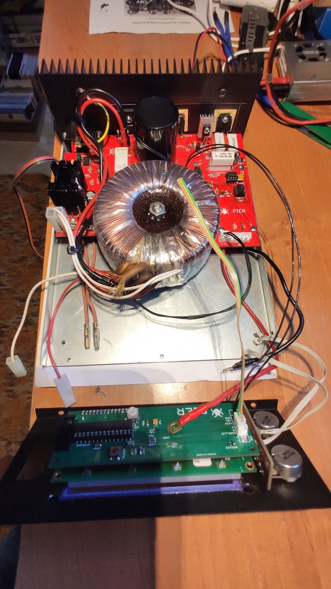
I spent a lot of time on the power supply board. I have equipped the power supply with a transformer winding switching system and a 12 and 5V auxiliary power supply. The rest is unchanged, except for changing the transistor controlling the output stage and adding a second power transistor. Such modifications are also standard in this design.
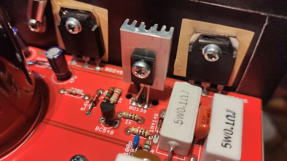
The mistakes I made on this board were the wrong footprint of the BD139 transistor, which meant that its legs had to be changed.

The rest are a few mislabeled resistors. Apparently nothing but I felt nervous when starting up.
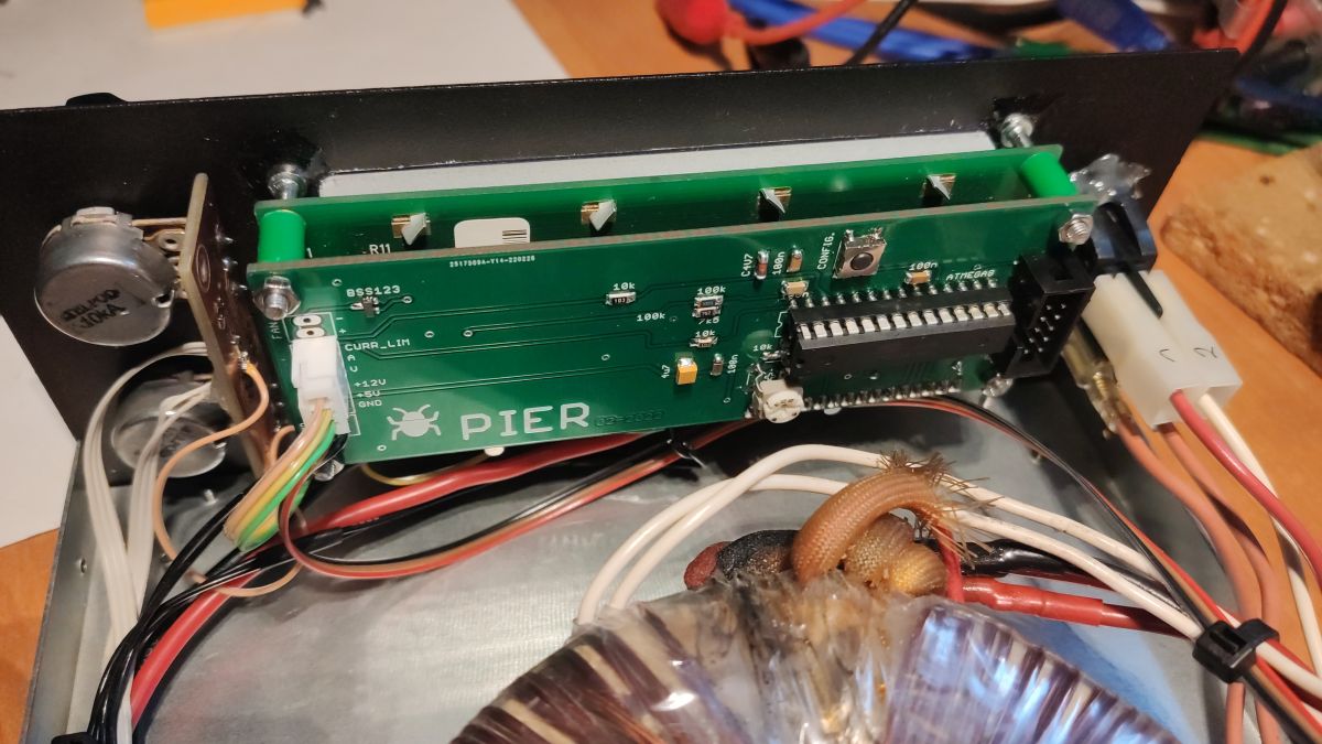
The meter is my design. It works, but it is still under development. So far, there is no option to calibrate indications or any configuration. The meter has the ability to control the fan, so far as you can see there is no fan, it only shows the temperature of the heat sink. On this PCB, I placed the connectors too close, so they do not fit next to each other and some wires had to be soldered directly into the PCB.
The meter is built on a large 2x16 display.
As you can see, the tiles are made in Asia, JLCPCB to be precise.
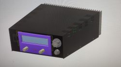
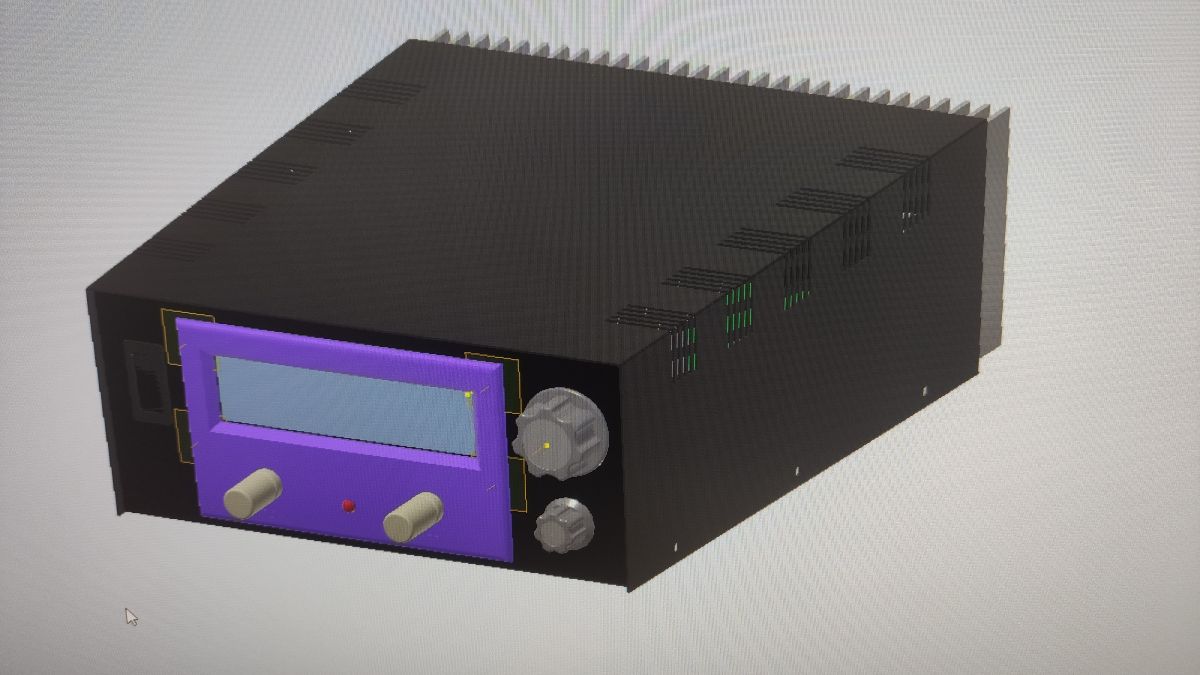
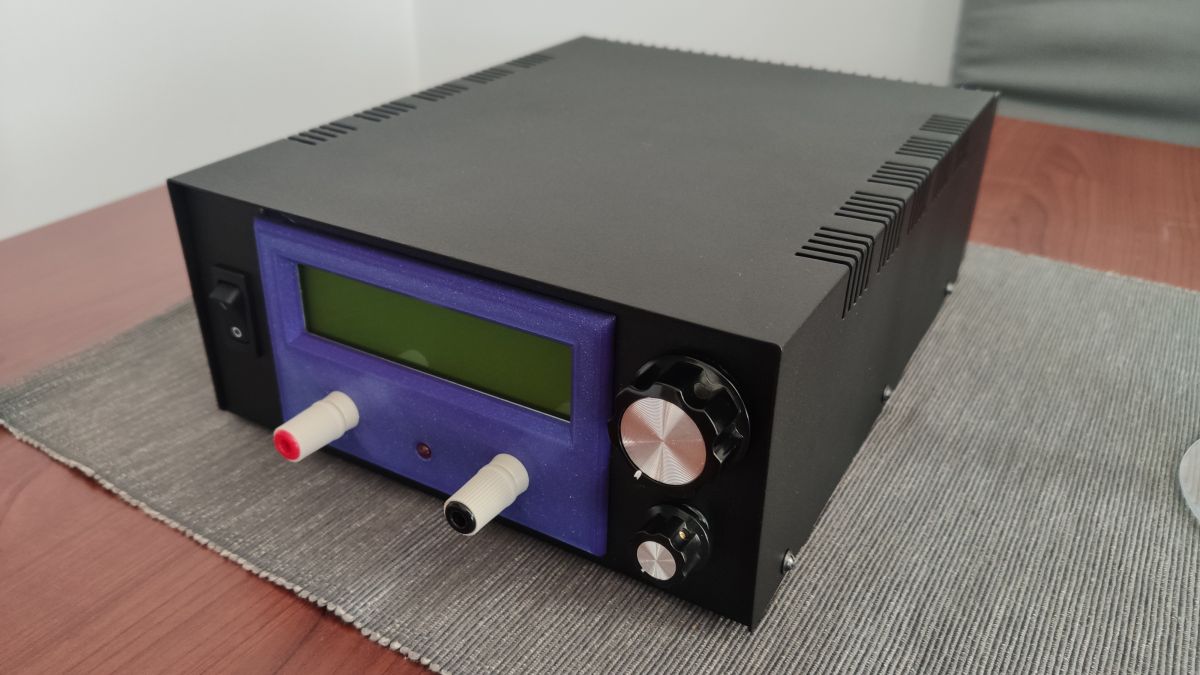
Everything is packed in the housing marked E208B. Very nice box, stiff. I was able to buy a heat sink that fits the housing perfectly, I just had to cut off a piece for the power socket.
The front panel, due to the dimensions of the housing and the display used, seems a bit non-functional, especially with the knobs, but I have no problem with operating them. Maybe the purple overlay on the LCD does not fit a bit, but it was just one that was available from the printer at the time. Yes, this plastic is specially designed and printed for this project. I was always attracted to the poor display in the housing. No descriptions on the panel because, first of all, I have no idea yet, and second, what should I describe here?
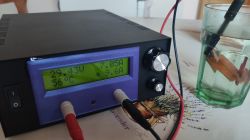
During the short tests, the power supply was fine. If I wanted to load it longer with maximum currents, I would have to think about another series resistor. The current 2x 0.47om 5W after three minutes with a current of 7A has a temperature close to 80 degrees. Bridge and heat sink transistors even do it. If it is something, I can add a fan.
The op-amps used still need to be explained.
In the design phase, I did not take into account the higher than acceptable voltage of the amplifiers from the second tap of the transformer. I thought, I advised on the forum how to figure it out. A quick solution would be to replace the amplifiers with those that can be powered with higher voltage, but the availability and prices of such cubes are not encouraging. The second option would be to add a stabilizer for op-amps, but this is an addition to the circuit and cutting paths.
In the end, the usual UA741 were left, yes, I know they work with too high supply voltage, but during the tests nothing happened with them. They work steadily and I have not noticed excessive heating. But of course, I do not recommend imitating.
Feel free to comment.
Greetings Piotr.


Comments
Plus for nice workmanship. Well, you'll see how it goes on, I'm far from criticizing. I have already covered this topic. I currently have 4 ElLabs power supplies. They work pretty well. ... [Read more]
You write that the tiles are made in Asia, which is what? Did you receive etched, drilled plates with solder mask and soldered everything yourself or did you receive plates with soldered elements? ... [Read more]
Absolutely, especially since you probably have the "+" and "-" sockets in the same color, so it's easy to make a mistake. You write about the ale amplifiers :) , you haven't added a diagram where... [Read more]
As for me, the center is very well made. The box is small and handy. [Read more]
Perhaps it looks like this on an amber CGA monitor, but for me the colors are obvious ... https://obrazki.elektroda.pl/4676685000_1650569335_bigthumb.jpg [Read more]
Well, I can see it now :) [Read more]
Nice idea with a display built-in. Only the effect is spoiled by this glue of glue :-) . [Read more]
I really like it, the aesthetically made work, I don't know how much the power supply weighs, and I don't know about you, but I would have a carrying handle like this: https://obrazki.elekt... [Read more]
It's probably not a glue blot, but a non-peeled foil protecting the display. [Read more]
Professional, tailor-made housing. Trafo solid, but the lack of detachments can quickly take its toll. Temperature measurement is a big plus, as is the fan. Take care of the current limitation while... [Read more]
I designed the tiles and the Chinese made them, that's how it works. I soldered myself. [Read more]
Nice workmanship - your own design as a whole? What is displayed on the LCD? [Read more]
The design of the power supply is from Electronic Lab, as I wrote. Mine is the tile design and all the rest. You can see what the LCD displays, maybe the current value with an asterisk requires some explanation.... [Read more]
The performance of the professor. I am asking for a diagram of the automatics of transformer winding switching. [Read more]
Thanks. Switch diagram taken from the electrode at the end of the topic are my suggestions. [Read more]
Certainly, this transformer is not so powerful, but it is enough for this power supply. If there was so much power, it would be worth doing a "soft" start. I would like to add that the "650" is the power... [Read more]
That's why I wrote 650W, I guess. It's hard to find the actual parameters of these ups. I think that the 8-10A from this is the optimal maximum that can be taken. [Read more]
By the way, luck with the UPSs, I obtained a Polish transformer from Sigma with the designation TF300SC. Typical EI core with dimensions as 40VA transformer. Here I found a short mention of him https://www.elektroda.pl/rtvforum/topic805069.html. ... [Read more]
Transformers in most UPSs have a power given as "UPS power" but first not in Watts, but in Voltoamers. Secondly, the vast majority of UPSs are designed for very short operation, usually 2-5 minutes under... [Read more]