This is a short teardown of the
Aubess Mini Smart Switch 16A which is based on
BK7231N and it uses a custom PCB ,so no Tuya module in there.
Basic Informations:
Brand: Aubess
Model: Aubess Mini Smart Switch 16A
Chip: BK7231N
Vendor (that's exactly where i bought it):
https://www.aliexpress.com/item/1005003631131323.html? <- it's the kind of seller that ask for extra shipping fees,so not really recommend it
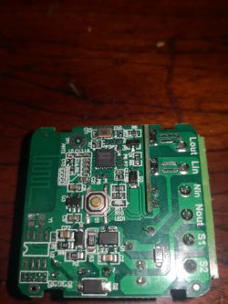
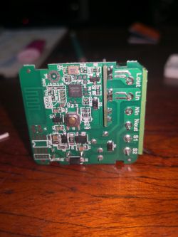
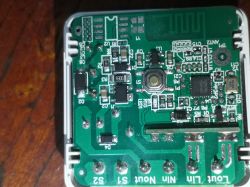
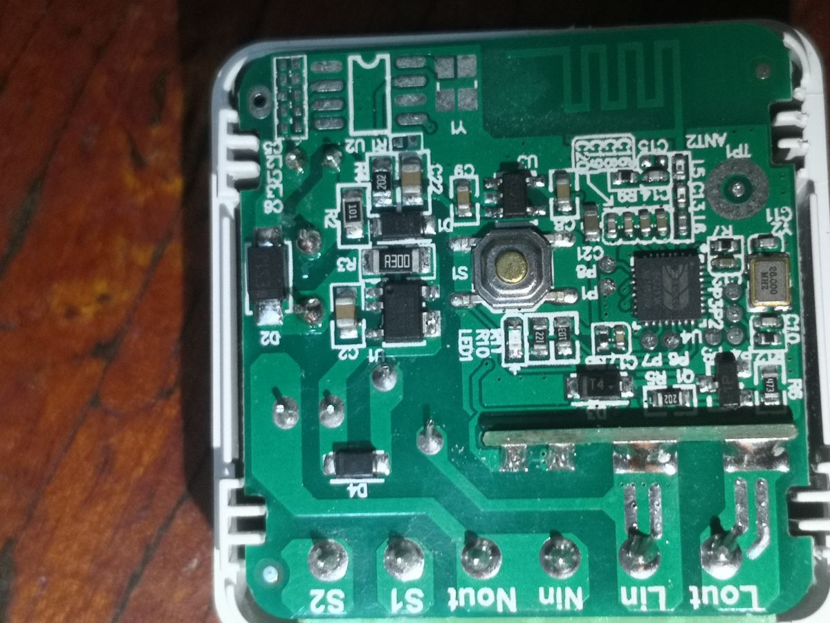
Teardown Photos
The switch is very easy to open so i wont go into details,but remember,this device it's using
high voltage,so make sure it's not connected to the mains.Also ,i took pictures only of the relevant parts.

Flashing OpenBeken firmware
Requirements:
USB to TTL adapter
Soldering Iron
Soldering skils (not pro level,but still...)
Magnifying glass or microscope are a plus
Steady hands
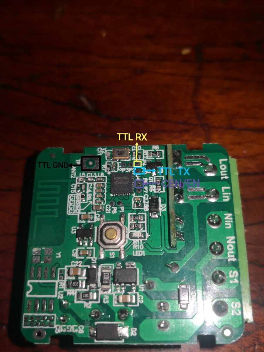
 Wiring:
 ->
Check the attached picture to locate the pins on the PCB
( PCB ) GND - > GND ( TTL )
( PCB ) TX - > RX ( TTL )
( PCB ) RX - > TX ( TTL )
( PCB ) CEN/EN -> GND ( PCB ) <-
CEN must be short to GND only for a second,in order to boot the chip in flash mode
Flashing: ->
In my case the 3.3v pin was not required at all.
1) Connect
GND,
RX and
TX to the
USB TTL then attach the TTL adapter to the PC.
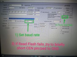
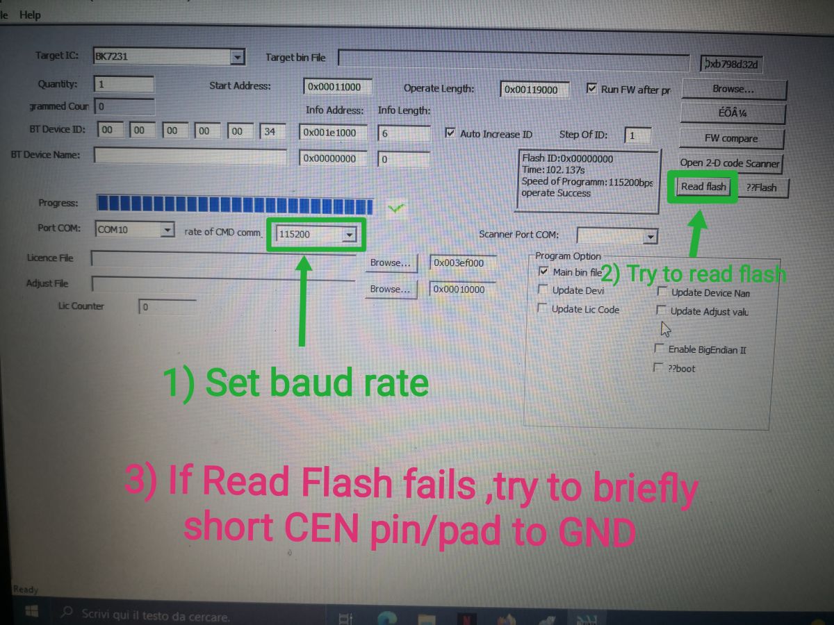
2) Open BKwriter 1.60 and set the baudrate (see attached picture)
3) Try to read the flash (if it fails ,then
short CEN to GND for a second then try again) <- this will create a backup of the original firmware
4) After BKwriter has finished the backup,you can proceed with the OpenBeken firmware flashing ,just follow the guide from
https://github.com/openshwprojects/OpenBK7231T_App/blob/main/README.md#flashing-for-bk7231n
5) After flashing Openbeken you should be able to find the quick configuration (i've sent a PR for that) for this device in ;
http://[Device_IP] > Config < Quick Config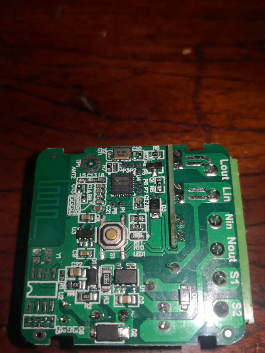

Comments
That's a very informative and helpful teardown. Futhermore, from what I see at the moment: https://obrazki.elektroda.pl/1309738100_1660641296_thumb.jpg The shipping to Poland is free and device... [Read more]
It was "free shipping " when i bought it too,but the seller asked for €0.50 more as extra shipping fee. However ,i had an Aliexpress coupon so it was still convenient ,that's why i agreed to pay... [Read more]
I bought a bunch of these devices from Aliexpress. They're branded as Aubess but use a different pin configuration than the ones already documented in this thread. https://obrazki.elektroda.pl/6581801300_1667148345_thumb.jpg... [Read more]
Hello, I'm trying to just read the firmware on a CB2S, see the picture https://obrazki.elektroda.pl/9000012400_1668112252_thumb.jpg However, I just get Speed of Programm:115200bps Init...FAILED Could... [Read more]
Here's a guide for dumping the Beken chip: https://docs.libretuya.ml/docs/platform/beken-72xx/dumping/ Using BkWriter is always discouraged, as it is very unstable. Use bk7231tools as instructed... [Read more]
Hello, Thanks for the reply, I have done the program using the command line tool, all went fine but...nothing is working. I have solded the module back and the blue led just stay still, no wifi network,... [Read more]
You may have flashed the incorrect binary file. Log output is available at TX2 pin. It should tell you what is happening. [Read more]
Thanks for this overview! I have exactly the same module from aliexpress. Everything is working fine except s1-s2 contacts. There is no effect if I short/open them. (no matter what mode is chosen in the... [Read more]
Hi, Not sure I understand your message but I think I have the same issue. I was able to flash it correctly, however, I can only control the led with the interface, the swicth do not work: https://obrazki.elektroda.pl/4398794800_1669200695_thumb.jpg... [Read more]
Why is the Relay not set for pin 26? Is there some issue with the template? https://obrazki.elektroda.pl/9887890100_1669202367_thumb.jpg Please try manually entering Relay for pin 26. [Read more]
I did but still nothing, the led go off and on when I click on/off in the web interface, but not the relay. https://obrazki.elektroda.pl/7041097400_1669204419_thumb.jpg I was wondering, if... [Read more]
If LED is going on and off then it means that you don't have configured relay correctly. Maybe relay is on some other pin. Maybe take some HD photos and show us the board, or check where the base of transistor... [Read more]
This is the board: https://obrazki.elektroda.pl/2969832700_1669206667_thumb.jpg It looks pretty similar to the one on the app template. I have solded the module back so the volts powering... [Read more]
U2 is the 3.3V LDO, so Q1 is most likely the transistor. Please check where it pins goes, one should go to Relay, and second one should go to WiFi module pin - check which pin. [Read more]
From Q1 : - middle pin is going to the switch (it can be seen also from the picture) - Left pin is going to GND - Right PIN doesn't go straing to any pin in the module, it goes to rp2 and then P... [Read more]
Can you go to Options, Configure Module and show what do you have here: https://obrazki.elektroda.pl/1339698800_1669215876_thumb.jpg ? Post a screenshot [Read more]
Mate, Apologies, just replaced the board with another one and everything isa working fine! it was a defective board, the wifi module is perfect. The template needs to ne updated though adding the... [Read more]
Board was defective? How? That's good if it works now. What kind of power meter? We are currently supporting BL0937, BL0942 and CSE*. [Read more]
Hi everyone, I've been exploring the flashing of those devices and the its operation with OpenBK7231N. I'm noob on this field so I apolagize in advance for any basic question I can place. I've used... [Read more]