
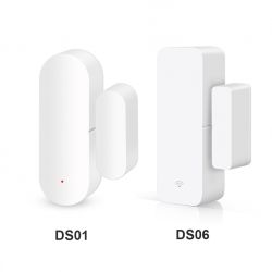
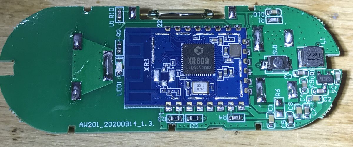
I will present here the interior of the Tuya WiFi door / window sensor implemented on the basis of two separate systems - a microcontroller (powered all the time) and a WiFi module (here: CB3S / BK7231N; powered only when you need to send information via WiFi) communicating via UART (TuyaMCU protocol but in version 0x00, not 0x03). I will also try to measure its power consumption in sleep mode. It will be a slightly different type of sensor than
previously reviewed made on the XR809 / XR3 WiFi module itself:
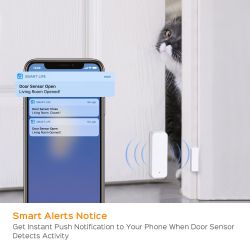
In this topic, I will focus on the operation of the DS06 sensor and its TuyaMCU communication protocol with the WiFi module.
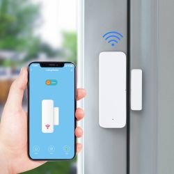
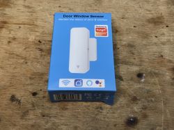
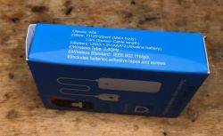
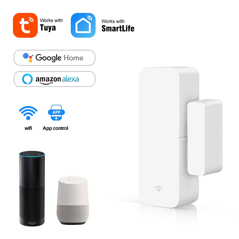
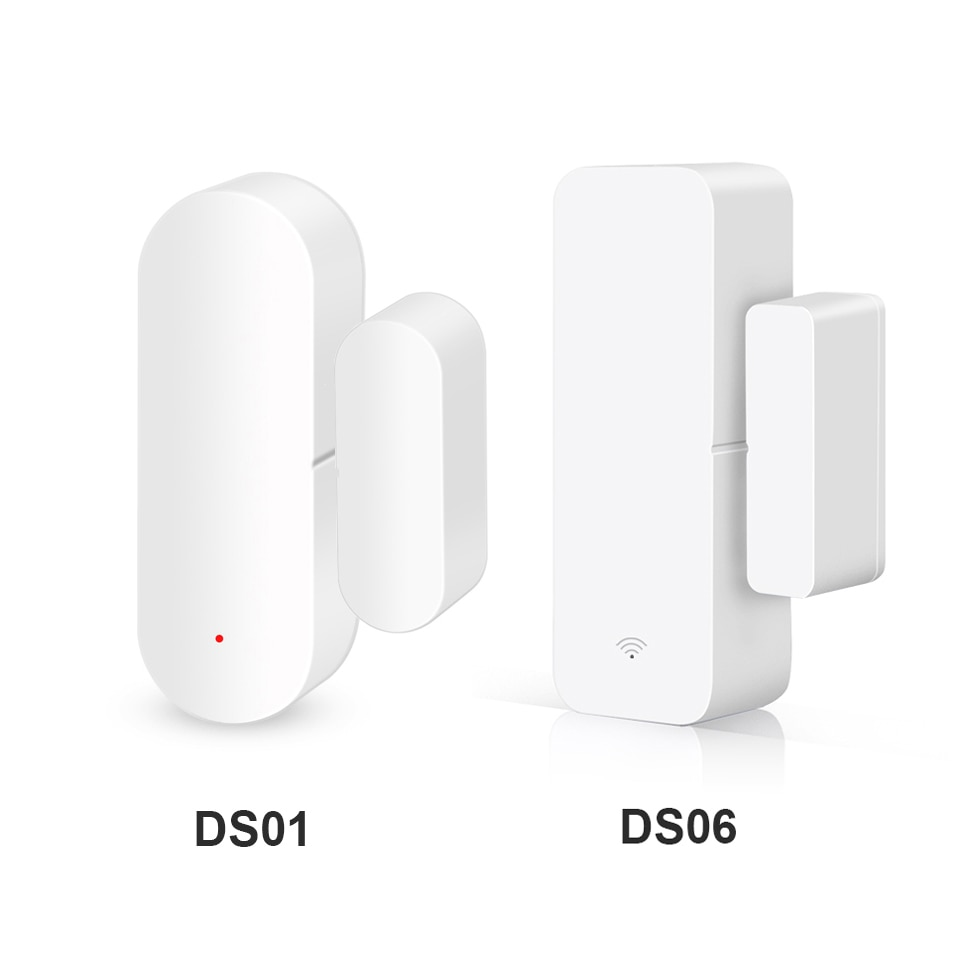
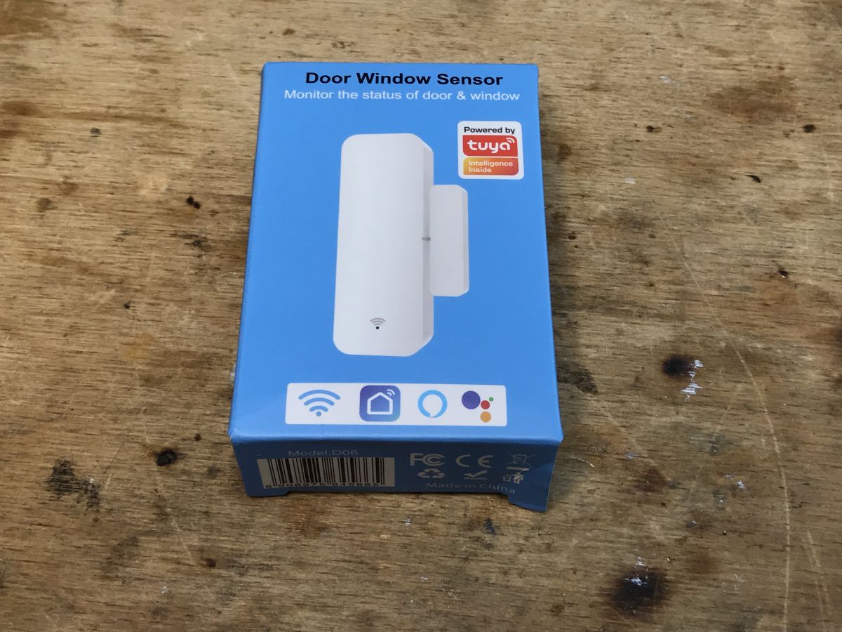
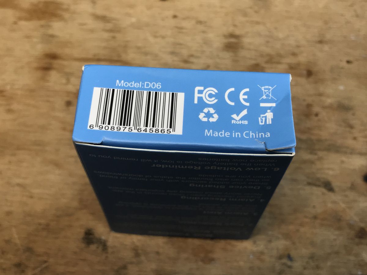
Purchase of a sensor I bought the product at the direct request of one of the users. You can find it on the web under the name "AVATTO Tuya WiFi Door Sensor, Smart Door Open / Closed Detectors, Smart Life APP Wifi Window Sensor Work with Alexa, Google Home" as well as under the model name: D06 / DS06. It costs about PLN 40.

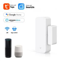
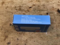
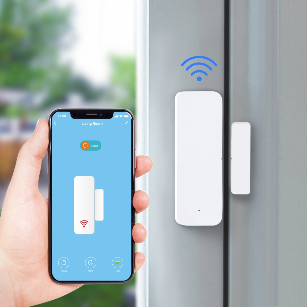
The product is advertised (truthfully) as compatible with the Tuya and SmartLife applications:

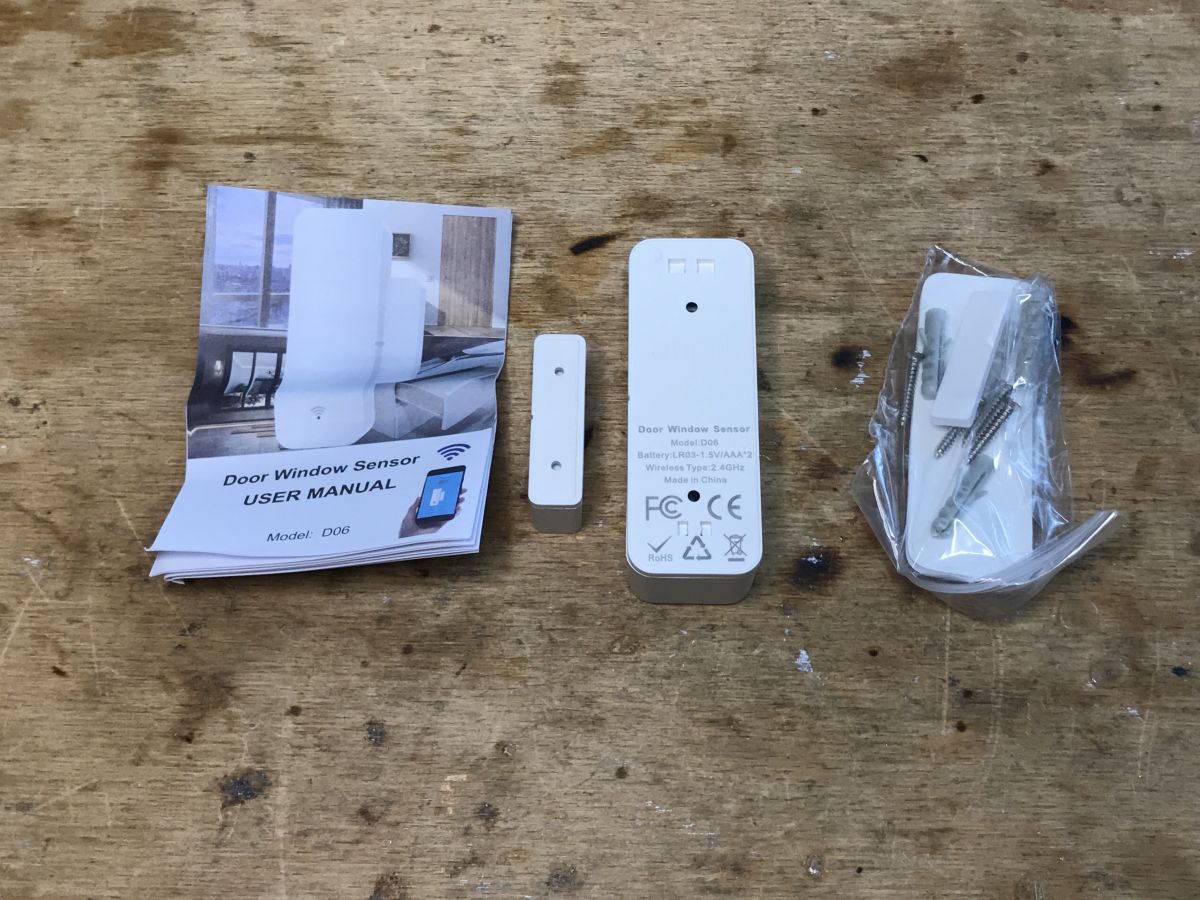
 Kit contents
 I waited a few weeks for the package again. It was brought by Pocztex, although it was given by "Sinotrans in the name and on behalf of Cainiao".

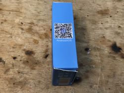
The packaging is in SmartLife blue (Tuya has orange), but it's all the same ecosystem:

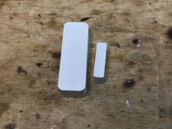
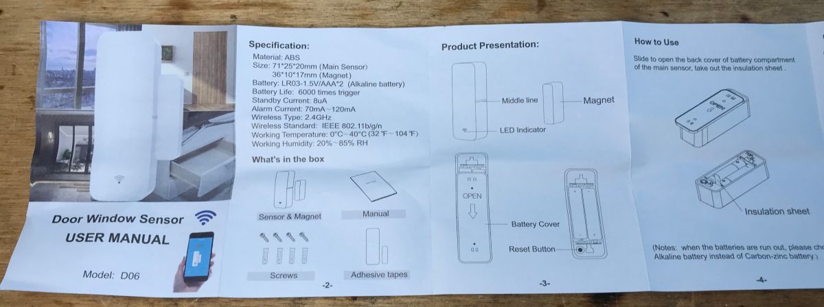
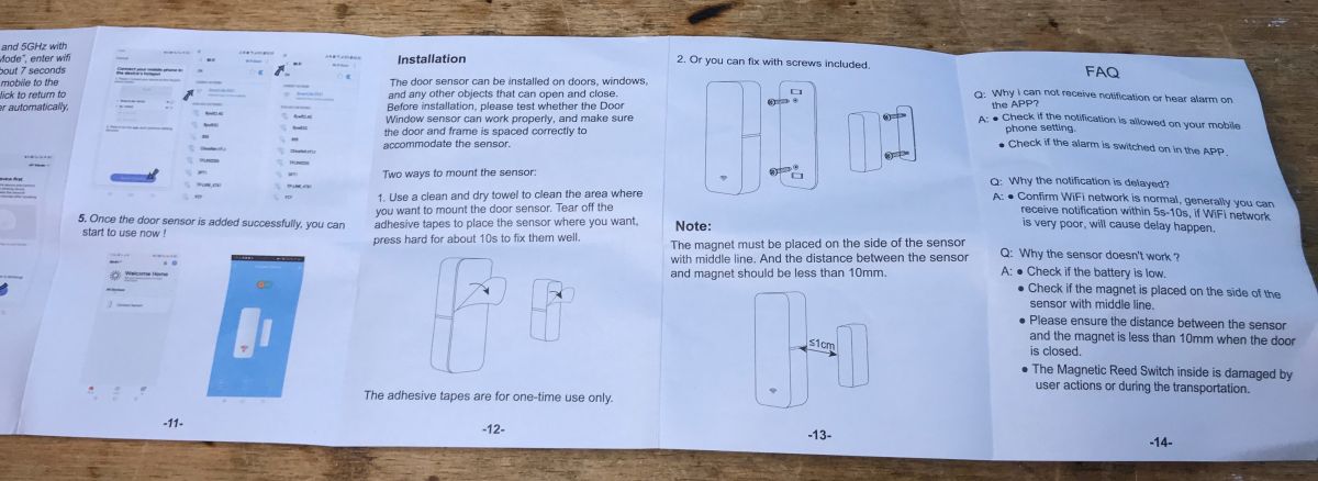
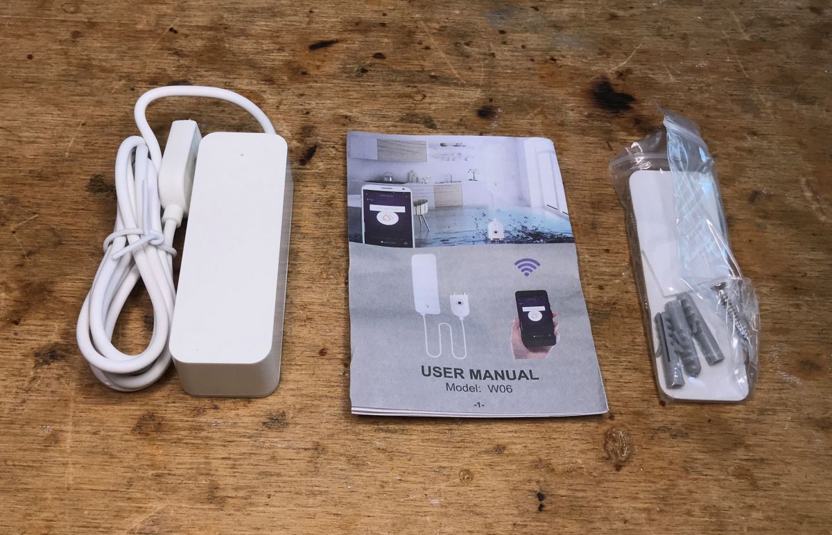
The set includes instructions, screws and tape for fixing:

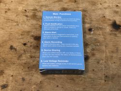
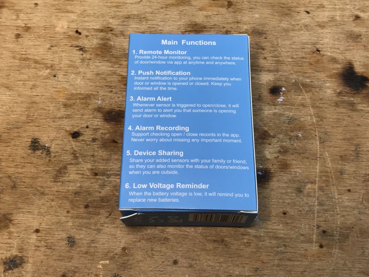
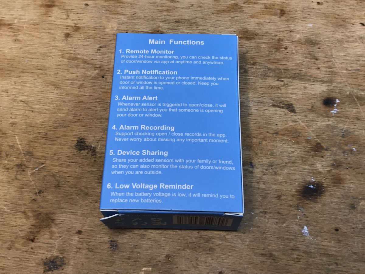
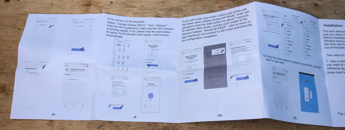
Instructions (pairing mode can be entered by pressing RESET for more than 7 seconds):


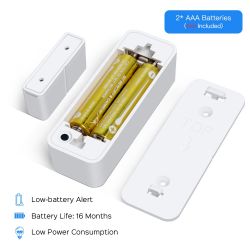
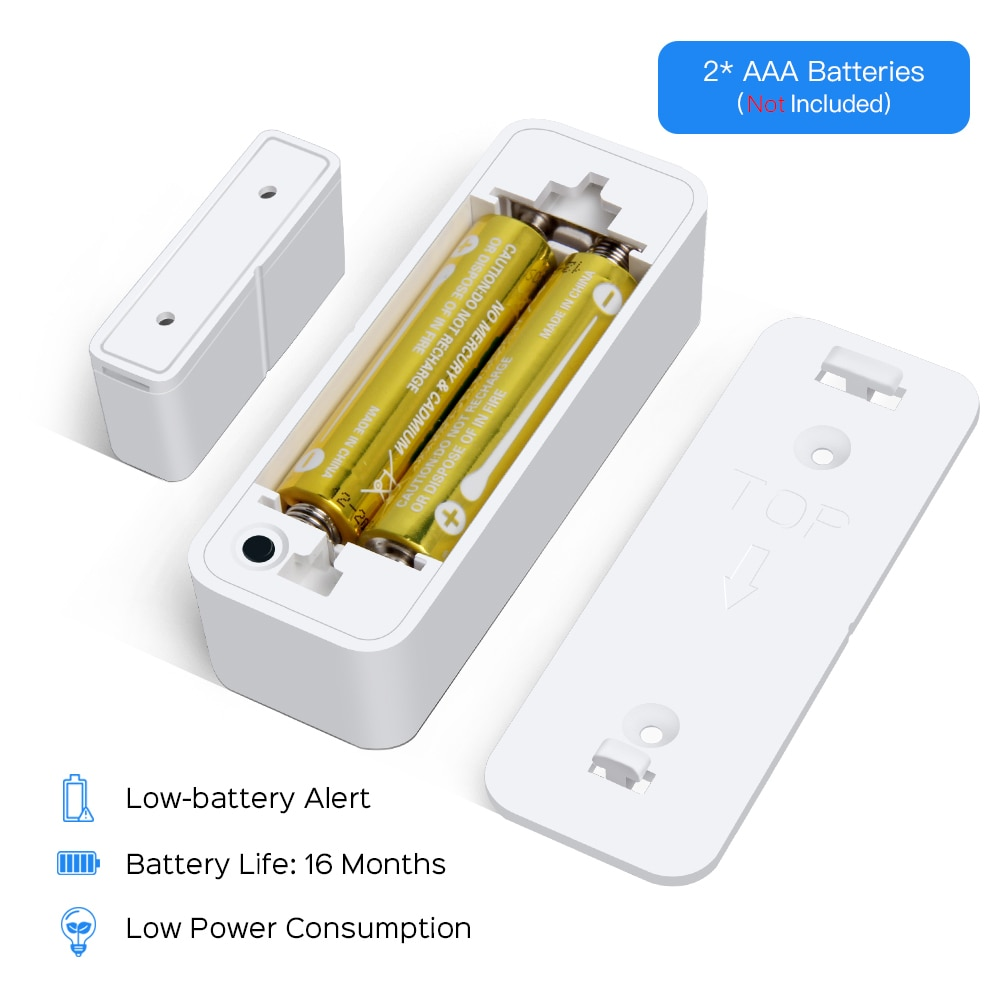
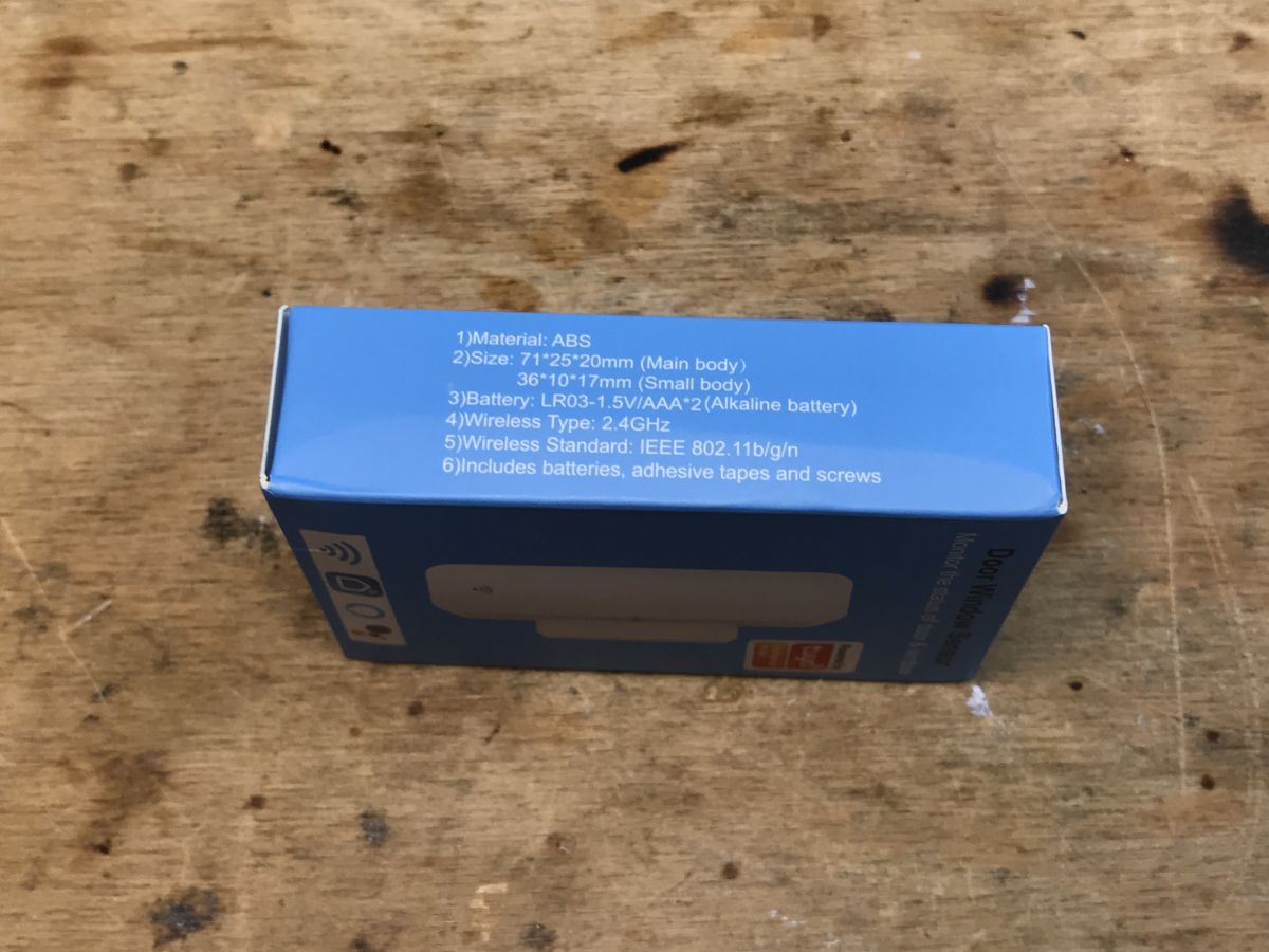
The sensor requires two AAA batteries:
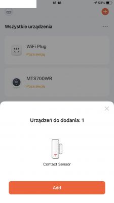
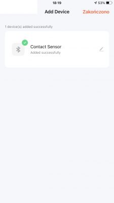
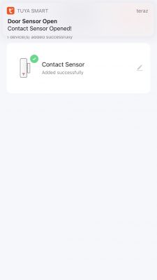
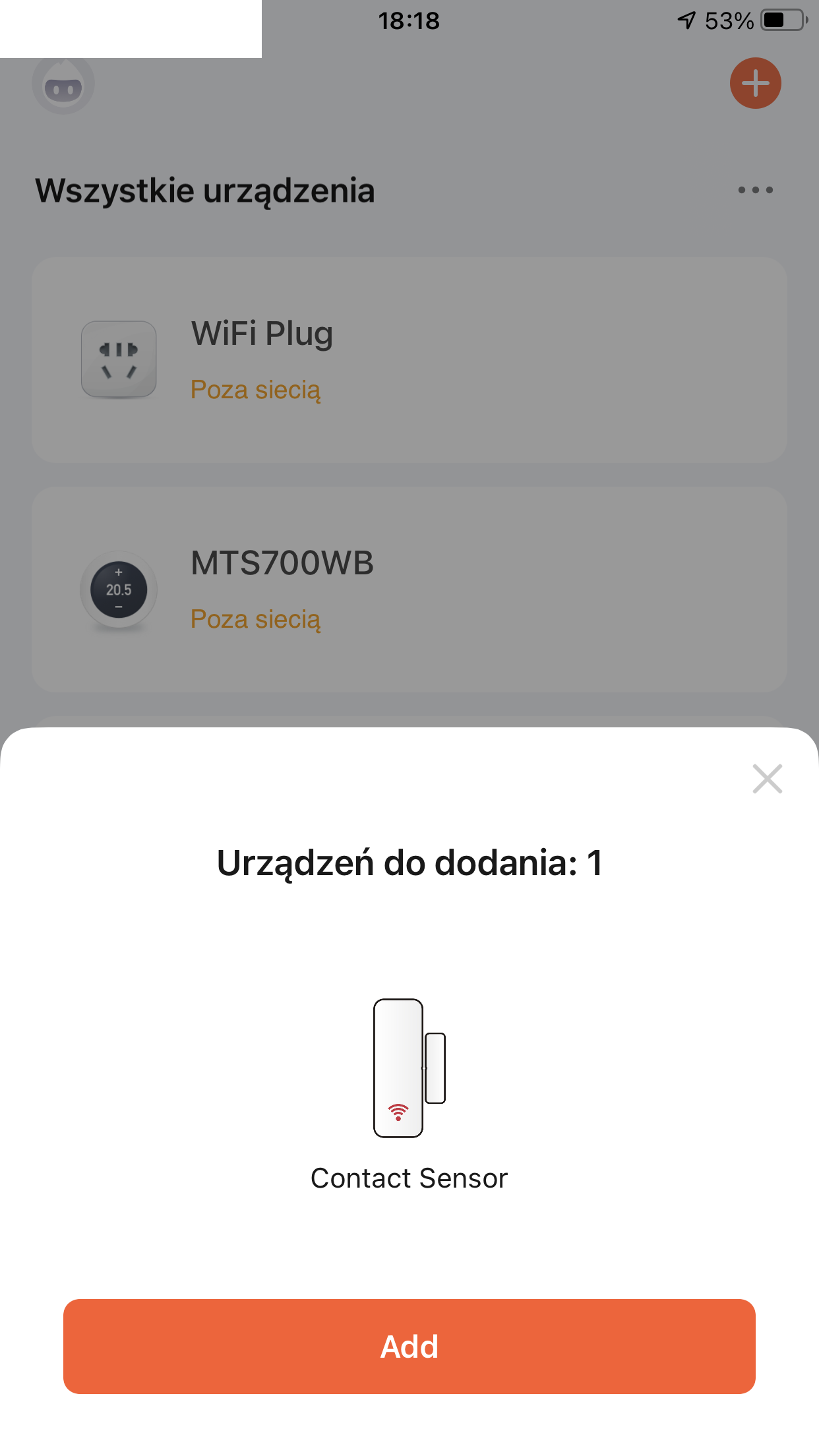
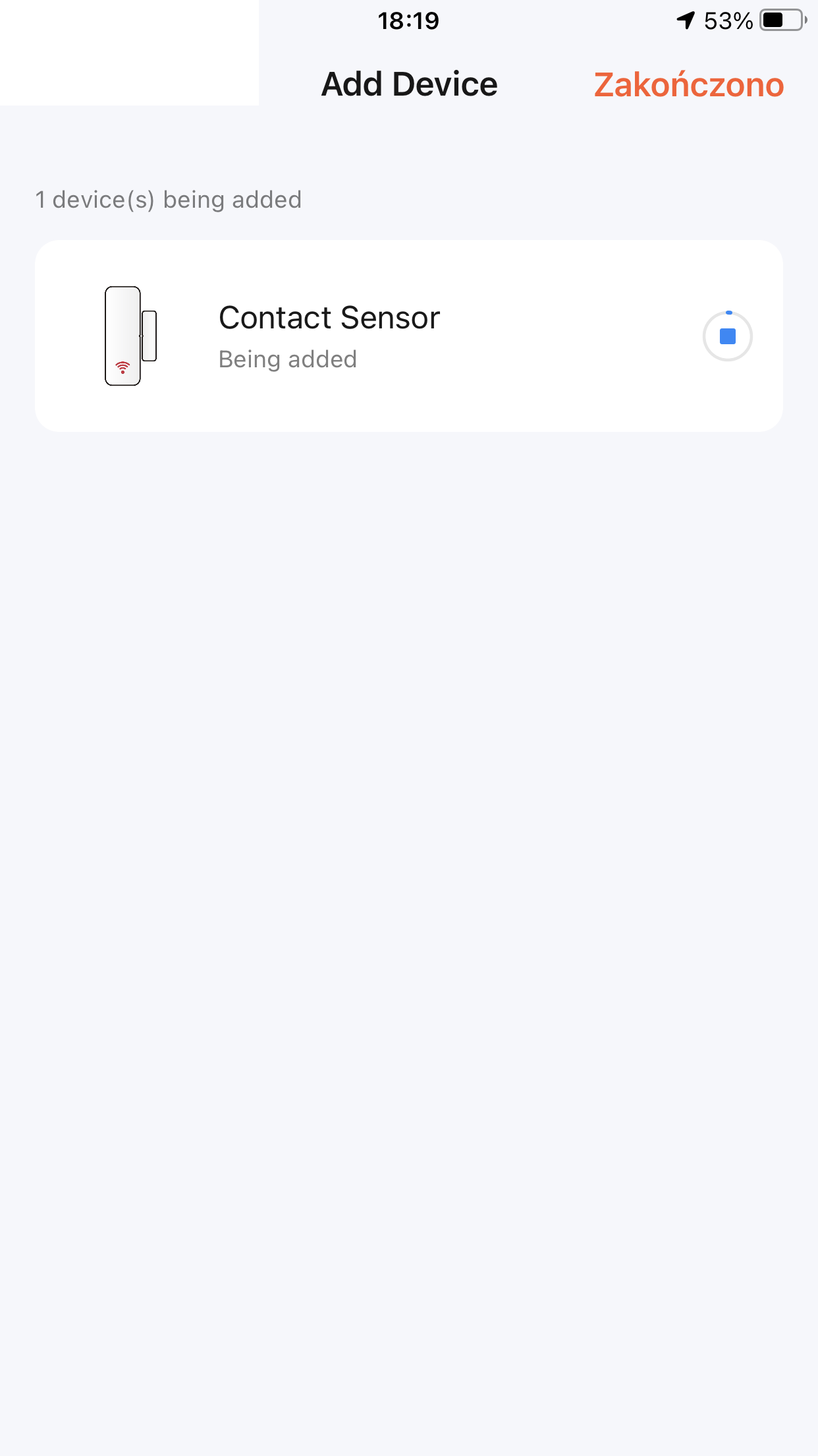
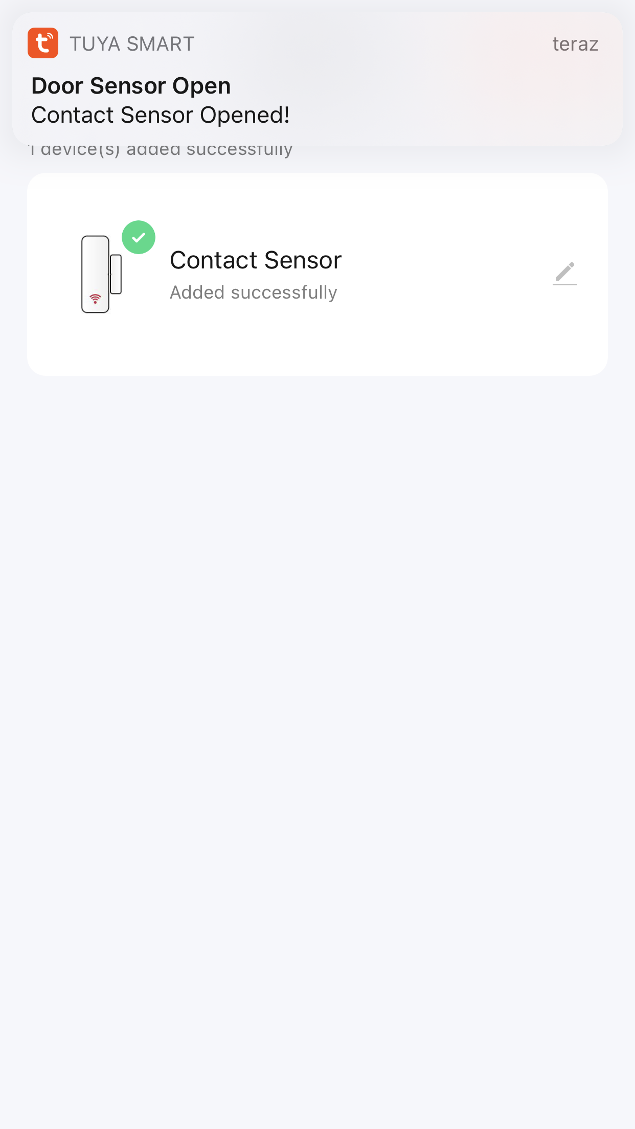
 Test with applicationTuya
 The sensor is repainted with SmartLife and the QR code leads to the SmartLife application, but is also compatible with the original, "orange" Tuya application:

You can create automation in it, but this has already been discussed in the forum several times.
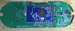
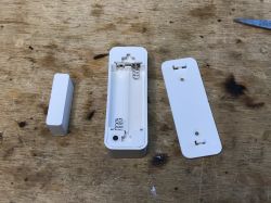
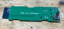
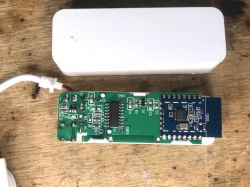
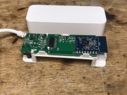
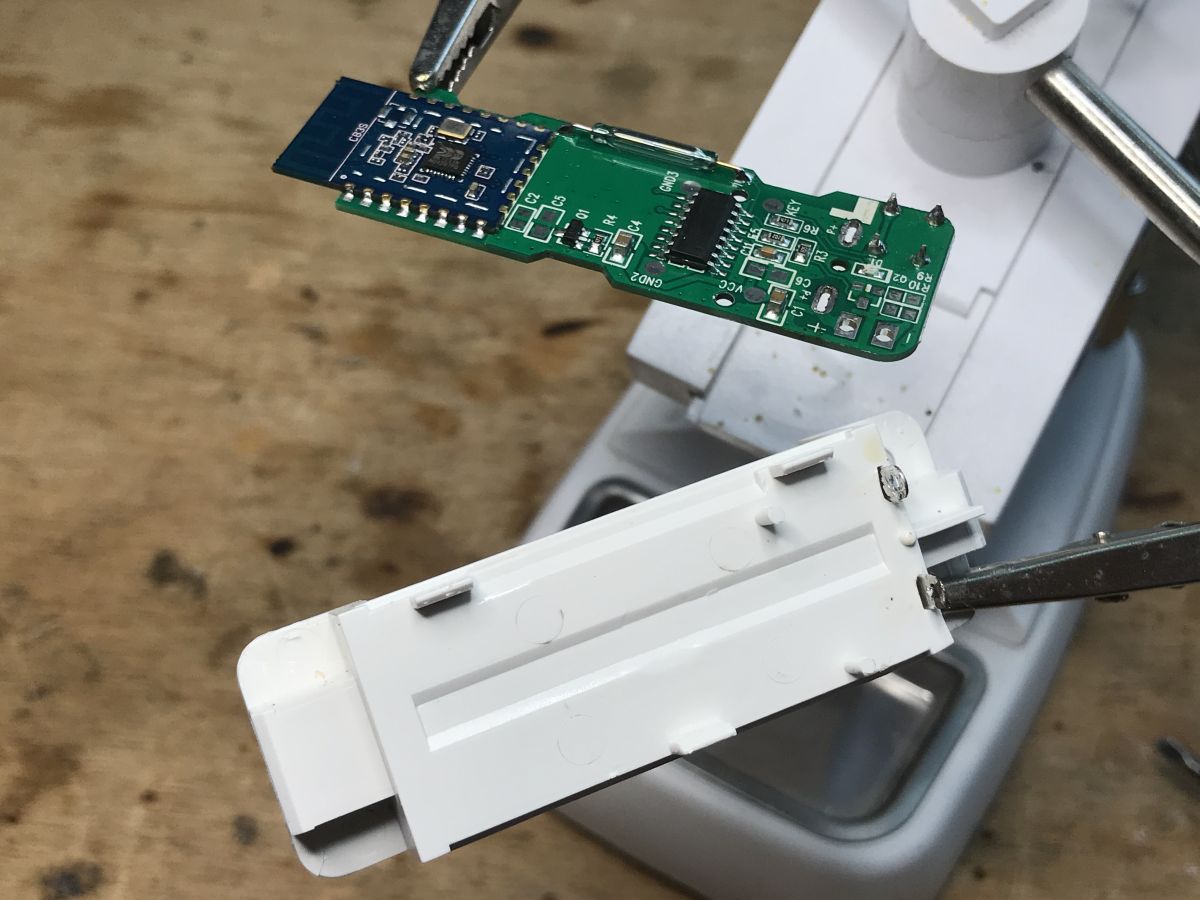
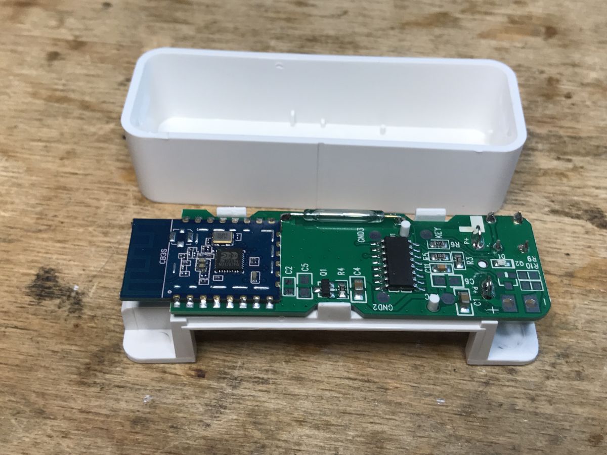
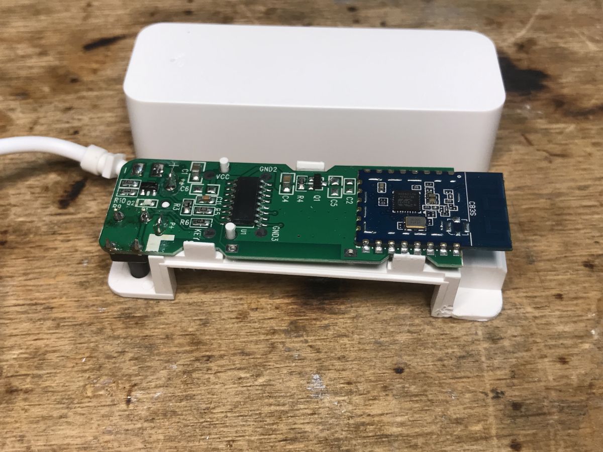
Interior of D06 It is enough to pry the housing with a knife:
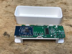
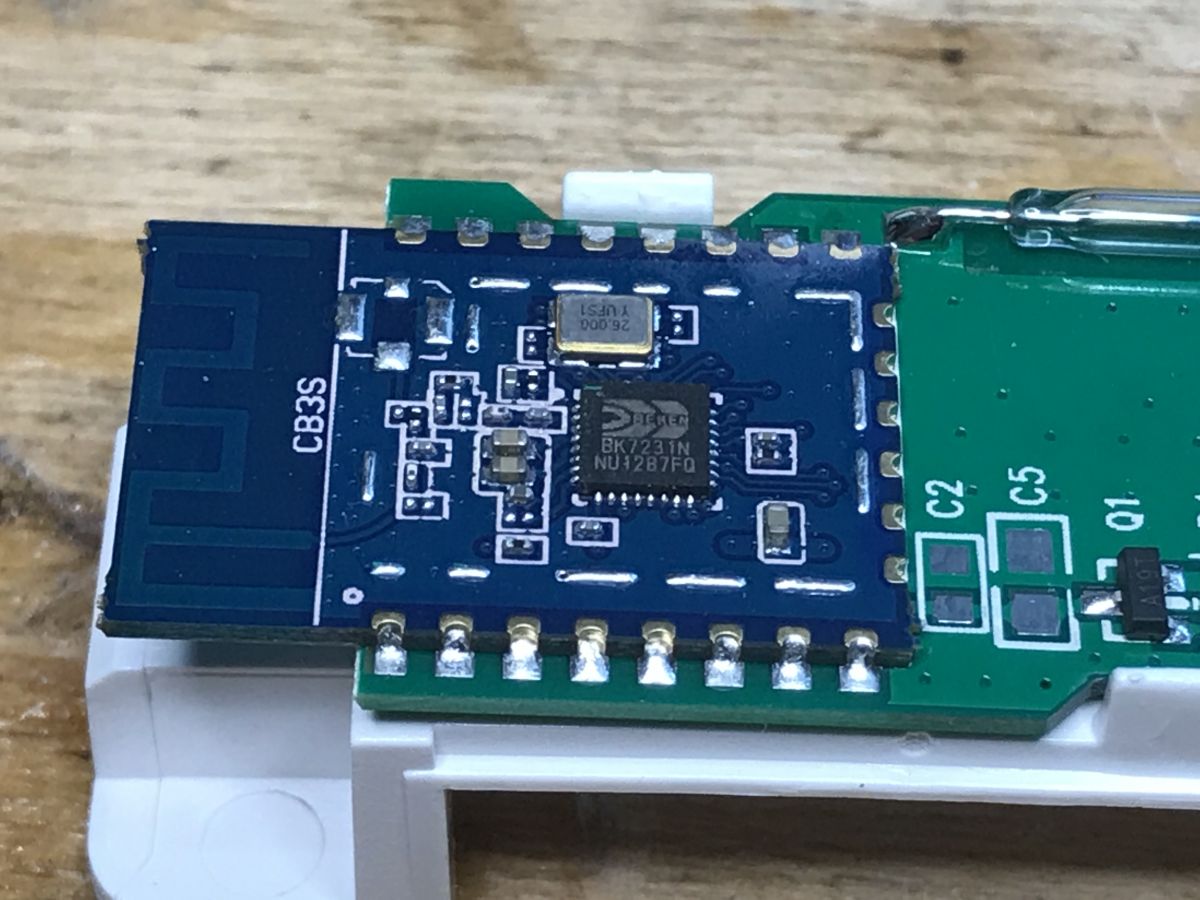
Inside there is a CB3S WiFi module (BK7231N) and a microcontroller (no marking):
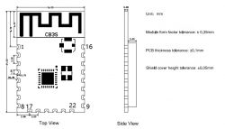
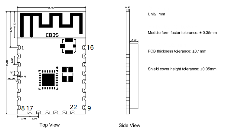
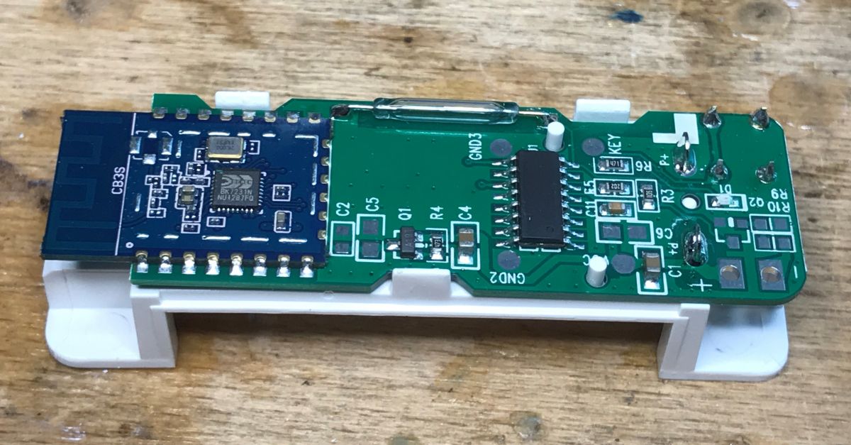
Leads of CB3S - from Tuya documentation:
| Pin number | Symbol | I / O type | Function |
| 1 | RST | AND | Low-level reset, high level active (the pin has been pulled high internally), correspond to CEN of the IC |
| 2 | ADC3 | AI | ADC pin, which corresponds to P23 of the IC |
| 3 | CEN | AND | Enabling pin, which is pulled high internally to be compatible with other modules |
| 4 | P14 | I/O | A common GPIO interface, which corresponds to P14 of the IC |
| 5 | P26 | I/O | GPIOP_26, which corresponds to P26 of the IC, PWM 5 |
| 6 | P24 | I/O | GPIOP_24, which corresponds to P24 of the IC, PWM 4 |
| 7 | P6 | I/O | GPIOP_6, which corresponds to P6 of the IC, PWM 0 |
| 8 | VCC | P | Power supply pin (3.3V) |
| 9 | GND | P | Power supply reference ground |
| 10 | P9 | I/O | GPIOP_9, which corresponds to P9 of the IC, PWM 3 |
| 11 | TXD2 | I/O | UART2_TXD (used to display the module internal information), which corresponds to P0 of the IC |
| 12 | CSN | I/O | Production test control pin. If it is used as a common I/O pin, it must be connected to the VCC externally. Do not connect it to the ground before the module is powered on. |
| 13 | P8 | I/O | GPIOP_8, which corresponds to P8 of the IC, PWM 2 |
| 14 | P7 | I/O | GPIOP_7, which corresponds to P7 of the IC, PWM 1 |
| 15 | RXD1 | I/O | UART1_RXD (user serial interface), which corresponds to P10 of the IC. Do not connect it to the VCC. By default, the MCU serial port should be in low-level or high-impedance state. |
| 16 | TXD1 | I/O | UART1_TXD (user serial interface), which corresponds to P11 of the IC. Do not connect it to the VCC. By default, the MCU serial port should be in low-level or high-impedance state. |
| 17 | ADC3 | AI | (Not recommended. If needed, please use Pin 2) ADC port, which corresponds to P23 of the IC. Programmed SPI |
| 18 | P22 | I/O | (Not recommended ) GPIOP_22, which corresponds to P22 of the IC. Programmed SPI |
| 19 | CSN | I/O | The pull-up resistor is needed during usage of customers. Do not connect it to the ground before the module is powered on. Correspond to P21 of the IC. |
| 20 | P20 | I / O | (Not recommended.) GPIOP_20, which corresponds to P20 of the IC. Programmed SPI |
| 21 | NC | - | - |
| 22 | NC | - | - |
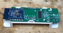


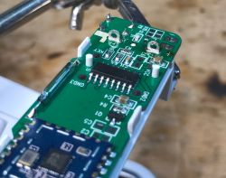
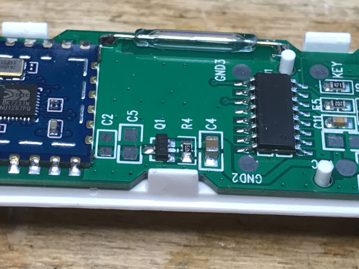
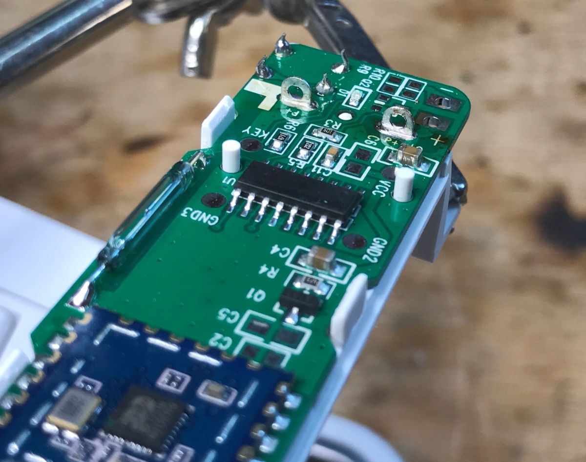
In order to analyze the tile in more detail, I first removed the binder with the braid and then removed it from the plastic base:
However, there is not much on the bottom:
On the basis of the collected knowledge, I have prepared a sketch of the connections:
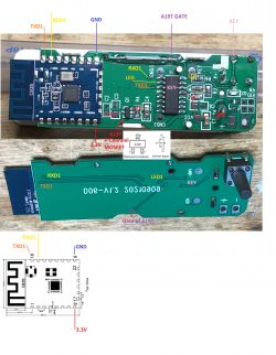
This door / window opening sensor works quite differently than the one I described in the past
sensor realized on XR809 (XR3) . Here, the WiFi module is normally turned off - only the microcontroller is still working. The microcontroller can only turn on the power
CB3S through the MOSFET transistor with P channel A19T when needed. This microcontroller communicates with the CB3S via the TuyaMCU protocol, but in the version for battery-powered devices, i.e. 0x00 and not 0x03.
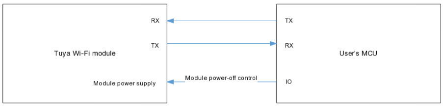
Simply put, the connection looks like this:

The artwork is from the official one
Tuya documentation .
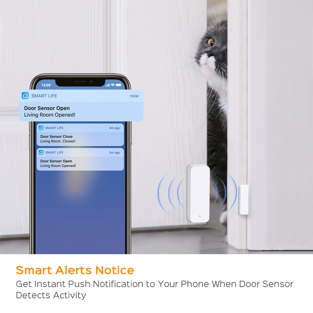
The method of reporting data by the sensor is illustrated by this algorithm:
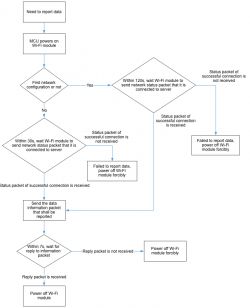
The WiFi module works for a really short period of time, normally only the microcontroller in the low power consumption mode listens for changes on the sensor.
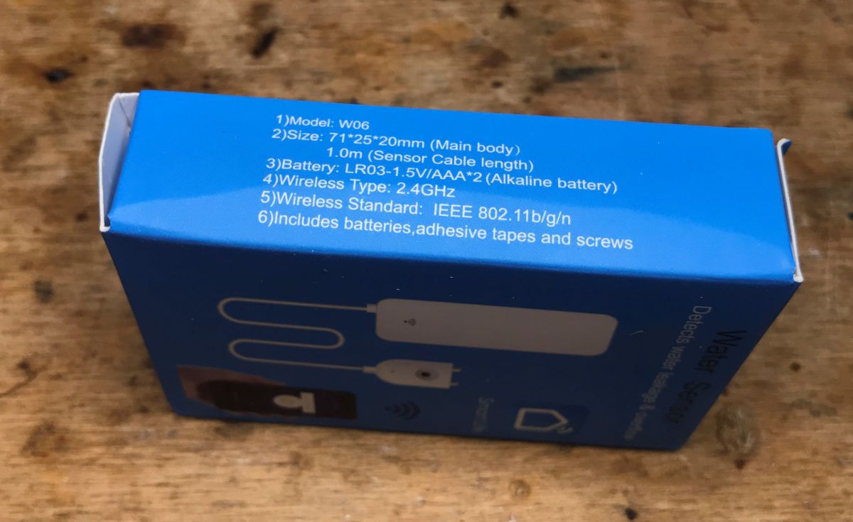
I do not describe the changes of the CB3S batch here, because it was discussed e.g. for CB2S, but I will only emphasize that the linesRX / TX are occupied by TuyaMCU, so if we want to program, we have to cut them off or unsolder that IC ... A twin product - flood sensor W06 As in the case of the previously discussed window opening / door sensor based on the XR809 module (but without TuyaMCU), this product is also sold in the form of a flood sensor - it is just the same PCB, the same circuits, but instead of the reed switch, the contacts are just brought out moisture sensor:

I performed the tests below on both devices - they work similarly.
The only difference is that we as a user know that the door open sensor is reporting
Open /
closed and the moisture sensor reports
wet /
dry . The packages themselves are identical.
Captured TuyaMCU packets to UART I intercepted at baud 9600. I leave packages here, among others. for myself for the future, when I will implement / finalize the support of this TuyaMCU version in
OpenBeken .
I described the basics of TuyaMCU here (it was a slightly different version, but most of it fits):
TuyaMCU protocol - communication between the microcontroller and the WiFi module . When analyzing packages, I recommend using the official documentation:
Serial Communication Protocol Activation. CB3S ships:
Quote:
55 AA 00 01 00 00 00
We have here (hex):
- heading - 55 AA
- version - 00
- command code - 01
- data length - 00 00
- checksum - 00
Command code 0x01 is getting product data - Query Product Information.
TuyaMCu replies:
Quote:
55 AA 00 01 00 24 7B 22 70 22 3A 22 65 37 64 6E 79 38 7A 76 6D 69 79 68 71 65 72 77 22 2C 22 76 22 3A 22 31 2E 30 2E 30 22 7D 24
The content of this packet (0x24 bytes long, i.e. 36 bytes in decimal) is ASCII text:
Quote:
55 AA 00 01 00 24 {"p": "e7dny8zvmiyhqerw", "v": "1.0.0"} $
Device ID + version.
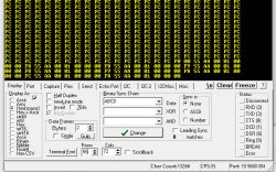
Already paired, contact closed when power was applied. (in the following quotes I have not divided separate request-reply pairs, only in the form of one block, I gave first what the CB3S sends and then what the microcontroller corresponds to) CB3S ships:
Quote:
00 00
55 AA 00 01 00 00 00
55 AA 00 02 00 01 04 06
55 AA 00 08 00 01 00 08
55 AA 00 08 00 01 00 08 00
TuyaMCu replies:
Quote:
00
55 AA 00 01 00 24 7B 22 70 22 3A 22 65 37 64 6E 79 38 7A 76 6D 69 79 68 71 65 72 77 22 2C 22 76 22 3A 22 31 2E 30 2E 30 22 7D 24
55 AA 00 02 00 00 01
55 AA 00 02 00 00 01
55 AA 00 08 00 0C 00 02 02 02 02 02 02 01 01 00 01 01 23
55 AA 00 08 00 0C 00 01 01 01 01 01 01 03 04 00 01 02 23 00
The message type 0x02 is a setting of the WiFi working status, and 0x08 is already sensor data, but more on that in a moment. First, a few more examples.
Already paired, device in sleep mode, I woke it up by closing the contact. CB3S ships:
Quote:
00
55 AA 00 01 00 24 7B 22 70 22 3A 22 65 37 64 6E 79 38 7A 76 6D 69 79 68 71 65 72 77 22 2C 22 76 22 3A 22 31 2E 30 2E 30 22 7D 24
55 AA 00 02 00 00 01
55 AA 00 02 00 00 01
head vr id size FL YY MM DD HH MM SS ID TP SIZE VL CK
55AA 00 08 000C 00 02 02 02 02 02 02 01 01 0001 00 22
head vr id size FL YY MM DD HH MM SS ID TP SIZE VL CK
55AA 00 08 000C 00 01 01 01 01 01 01 03 04 0001 02 23
Under the package I wrote what is what - head (header), vr (version), id (package identifier), size (size), FL (flag), then date values, then ID (dpID / fnID, i.e. the name of the variable) , TP (type), SIZE (variable value size), VL (value - its value), CK - checksum, checksum. Already paired, device in sleep mode, I woke it up by opening the contact. CB3S ships:
Quote:
00
55 AA 00 01 00 24 7B 22 70 22 3A 22 65 37 64 6E 79 38 7A 76 6D 69 79 68 71 65 72 77 22 2C 22 76 22 3A 22 31 2E 30 2E 30 22 7D 24
55 AA 00 02 00 00 01
55 AA 00 02 00 00 01
head vr id size FL YY MM DD HH MM SS ID TP SIZE VL CK
55AA 00 08 000C 00 02 02 02 02 02 02 01 01 0001 01 23
head vr id size FL YY MM DD HH MM SS ID TP SIZE VL CK
55AA 00 08 000C 00 01 01 01 01 01 01 03 04 0001 02 23
00
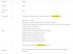
Packets of the 0x08 type (data) contain date / time (incorrect here), marked by me as YY MM DD HH MM SS, a flag that determines the correctness of the date (my FL designation) and additional data, the so-called data point, ID (variable id), TP (its type), SIZE (its size) and VL (its value).
It is the VL value that determines the state of the door sensor.
Below are screenshots describing the structure of this package from the documentation:
 Already paired, device in sleep mode, I woke it up by pressing the RESET button.
 CB3S ships:
Quote:
00
55 AA 00 01 00 00 00 (01 = Query Product Information)
55 AA 00 02 00 01 03 05 (02 = MCU Conf)
55 AA 00 02 00 01 04 06 (02 = MCU Conf)
55 AA 00 08 00 01 00 08 00 (08 = Query State)
TuyaMCU replies:
Quote:
00
55 AA 00 01 00 24 7B 22 70 22 3A 22 65 37 64 6E 79 38 7A 76 6D 69 79 68 71 65 72 77 22 2C 22 76 22 3A 22 31 2E 30 2E 30 22 7D 24 (01 = Query Product Information)
55 AA 00 02 00 00 01 (02 = MCU Conf)
55 AA 00 02 00 00 01 (02 = MCU Conf)
head vr id size FL YY MM DD HH MM SS ID TP SIZE VL CK
55AA 00 08 000C 00 01 01 01 01 01 01 03 04 0001 02 23 00 (08 = Query State)
Experiment: what does CB2S send itself when we cut off RX and TX paths and reboot? Just for the sake of principle - it should be clear.
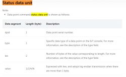
Let's break down the contents of the package:
Let me remind you, we have in turn:
- 55AA - header
- 00 - version
- 0100 - length 1 byte
- 00 - data
- 00 - checksum
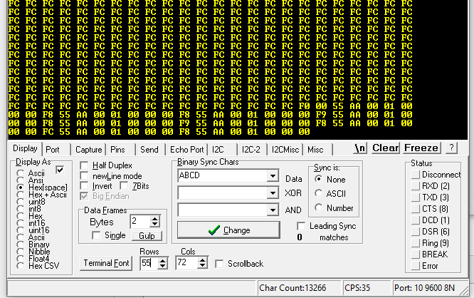
The repeating F8 / F9 looks like a glitch, it is not part of the packet.
Experiment: what does TuyaMCU itself send after cutting off TX and RX? Surprisingly, however, it sends something - probably to keep the connection:
A zero byte every few seconds. Or it's a disruption.
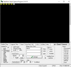
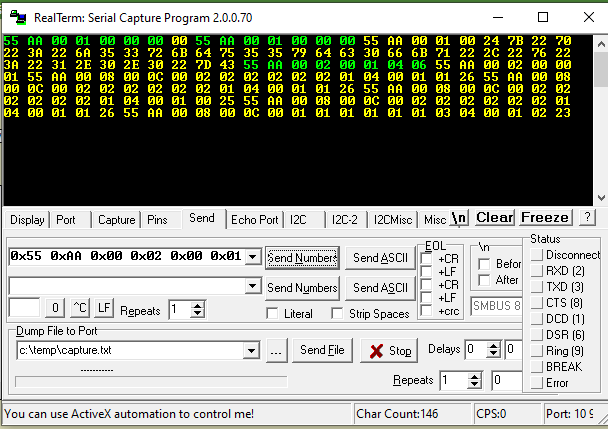
And what if after starting the power supply, we will send a request for identification to TuyaMCU: Quote:
0x55 0xAA 0x00 0x01 0x00 0x00 0x00
Response:
Quote:
55 AA 00 01 00 24 7B 22 70 22 3A 22 6A 35 33 72 6B
64 75 35 35 79 64 63 30 66 6B 71 22 2C 22 76 22 3A 22 31 2E 30 2E 30 22
7D 43
Yes - this is already the packet discussed with an ASCII value of type
{"P": "vHXEcqntLpkAl ***", "v": "1.0.0 "} ;
Screenshot:
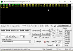
How do we try to ask him about his condition?
0x55 0xAA 0x00 0x08 0x00 0x01 0x00 0x08
No answer.
You have to send the configuration first, then you can ask for Data Points 0x08:
0x55 0xAA 0x00 0x02 0x00 0x01 0x04 0x06
Below is the entire transaction:
Broken answers:
55 AA 00 02 00 00 01
55 AA 00 08 00 0C 00 02 02 02 02 02 02 01 04 00 01 01 26
55 AA 00 08 00 0C 00 02 02 02 02 02 02 01 04 00 01 01 26
55 AA 00 08 00 0C 00 02 02 02 02 02 02 01 04 00 01 00 25
55 AA 00 08 00 0C 00 02 02 02 02 02 02 01 04 00 01 01 26
55 AA 00 08 00 0C 00 01 01 01 01 01 01 03 04 00 01 02 23
55 AA 00 02 00 01 04 06
55 AA 00 02 00 00 01
55 AA 00 08 00 0C 00 02 02 02 02 02 02 01 04 00 01 01 26
55 AA 00 08 00 0C 00 01 01 01 01 01 01 03 04 00 01 02 23
55 AA 00 08 00 0C 00 02 02 02 02 02 02 01 04 00 01 00 25
55 AA 00 08 00 0C 00 01 01 01 01 01 01 03 04 00 01 02 23
55 AA 00 02 00 01 04 06
55 AA 00 02 00 00 01
55 AA 00 08 00 0C 00 02 02 02 02 02 02 01 04 00 01 00 25
55 AA 00 08 00 0C 00 01 01 01 01 01 01 03 04 00 01 02 23
55 AA 00 08 00 0C 00 01 01 01 01 01 01 ID TP LENG  VL CH
55 AA 00 02 00 00 01
55 AA 00 08 00 0C 00 02 02 02 02 02 02 01 04 00 01 01 26
55 AA 00 08 00 0C 00 02 02 02 02 02 02 01 04 00 01 00 25
55 AA 00 08 00 0C 00 02 02 02 02 02 02 01 04 00 01 01 26
55 AA 00 08 00 0C 00 02 02 02 02 02 02 01 04 00 01 01 26
55 AA 00 08 00 0C 00 02 02 02 02 02 02 01 04 00 01 01 26
55 AA 00 08 00 0C 00 02 02 02 02 02 02 01 04 00 01 01 26
55 AA 00 08 00 0C 00 02 02 02 02 02 02 01 04 00 01 00 25
55 AA 00 08 00 0C 00 02 02 02 02 02 02 01 04 00 01 01 26
55 AA 00 08 00 0C 00 01 01 01 01 01 01 03 04 00 01 02 23
55 AA 00 08 00 0C 00 01 01 01 01 01 01 ID TP LENG  VL CH
Wet (or actually putting the sensor in the water):
55 AA 00 02 00 01 04 06
55 AA 00 02 00 00 01
55 AA 00 08 00 0C 00 02 02 02 02 02 02 01 04 00 01 01 26
55 AA 00 08 00 0C 00 02 02 02 02 02 02 01 04 00 01 00 25
55 AA 00 08 00 0C 00 01 01 01 01 01 01 03 04 00 01 02 23
55 AA 00 08 00 0C 00 01 01 01 01 01 01 ID TP LENG  VL CH
55 AA 00 02 00 01 04 06
55 AA 00 02 00 00 01
Dry:
55 AA 00 08 00 0C 00 02 02 02 02 02 02 01 04 00 01 01 26
55 AA 00 08 00 0C 00 01 01 01 01 01 01 03 04 00 01 02 23
55 AA 00 08 00 0C 00 01 01 01 01 01 01 ID TP LENG  VL CH
Can you see the difference?
Please do not pay attention to the last value, it is a checksum, you know that it changes.
Wet:
55 AA 00 08 00 0C 00 02 02 02 02 02 02 01 04 00 01 00 25
55 AA 00 08 00 0C 00 01 01 01 01 01 01 ID TP LENG  VL CH
Dry:
55 AA 00 08 00 0C 00 02 02 02 02 02 02 01 04 00 01 01 26
55 AA 00 08 00 0C 00 01 01 01 01 01 01 ID TP LENG  VL CH
A packet with ID 0x01 (dpID or fnID 0x01) changes the value from 1 (VL, Value) to 0.
We also have ID 0x03:
55 AA 00 08 00 0C 00 01 01 01 01 01 01 03 04 00 01 02 23
... but this is the state of the battery (value, VL, 02).
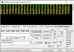
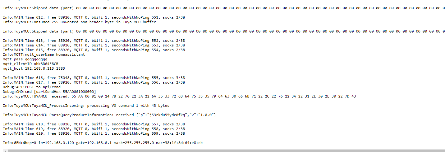
Finally, I did a test in OpenBeken - both systems powered separately from 3.3V, the microcontroller awakened, the strange 00 00 00 in the tuyaMCU buffer appear when the microcontroller is asleep (its UART is turned off) and the WiFi module works in an artificial way (we additionally powered it):
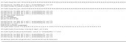
OpenBeken is able to receive the MCU Identification packet.
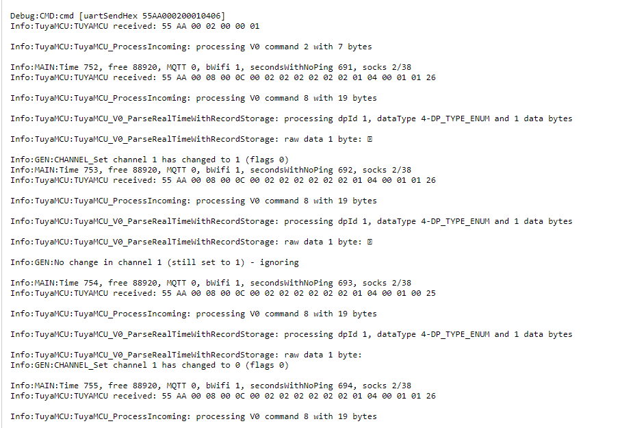
However, if we send the 0x02 configuration package ourselves (in the screenshot by the uartSendHex command), then CB3S will also send us the 0x08 package with the variable states:
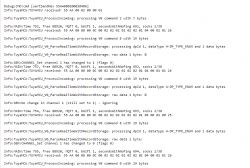
Summarizing, the above data shows that two variables TuyaMCU (data points) in the package 0x08 are used in these sensors:
- dpID 1 - sensor status, 0 or 1 (for a door sensor it is open / close, for a moisture sensor it is wet / dry)
- dpID 3 - battery status, from 3 (full) to 0 (or 1 - not checked).
These data are reported by TuyaMCU after the WiFi module has been identified.
Configuration in OpenBeken My
OpenBeken it already supports this sensor, but I haven't fully tested the full functionality yet.
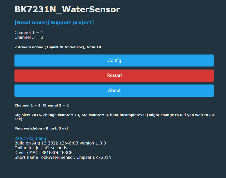
To support this sensor, you need to turn on two "drivers", one TuyaMCU and the other tmSensor. TuyaMCU handles the UART communication base, and the tmSensor itself sends out state inquiries (remember - the WiFi module first responds to TuyaMCU via UART).
Here is the OpenBeken command line (I entered it in the startup command to be executed at startup):
backlog startDriver tuyaMCU; startDriver tmSensor; linkTuyaMCUOutputToChannel 1 val 1; setChannelType 1 ReadOnly; linkTuyaMCUOutputToChannel 3 val 3; setChannelType 3 ReadOnly;
Channels / dpID the same as above - 1 and 3. One is the state of the sensor, the other is the battery.
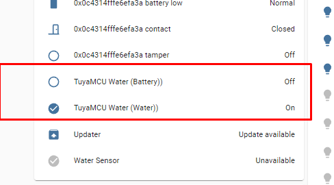
Yaml configuration in Home Assistant (this example is for a water sensor, but as I wrote, it's the same system, only a different sensor, the door opening sensor works similarly):
I have not done the battery reading yet - I will post the full version in the next topic.
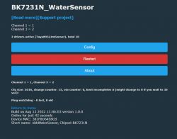
Screenshot from the panel:
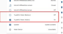
View in HA:
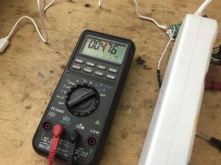
 Power consumption in sleep and data upload mode
 The microcontroller only activates the WiFi module when data needs to be sent, but how much electricity does it save? Sleep mode:
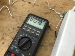
Sending data (current flows about 70mA here)
 Summary
 This door / window opening sensor is indeed different from the sensor discussed earlier, which is based on the XR809. Adding a microcontroller that turns on the WiFi module whenever you need to send new information to the server certainly allows to save energy to some extent and extends battery life, but also complicates the system itself and makes it difficult to add its support to my firmware.
My measurements show that the current consumption in MCU sleep mode is about 5 uA. It is worth mentioning that then the MCU even turns off its UART (I checked - it does not respond) and only waits for a signal from the sensor or sensor.
As soon as the signal is received, the WiFi module is on and the power consumption is up to 70mA or more, depending on what the WiFi is doing.
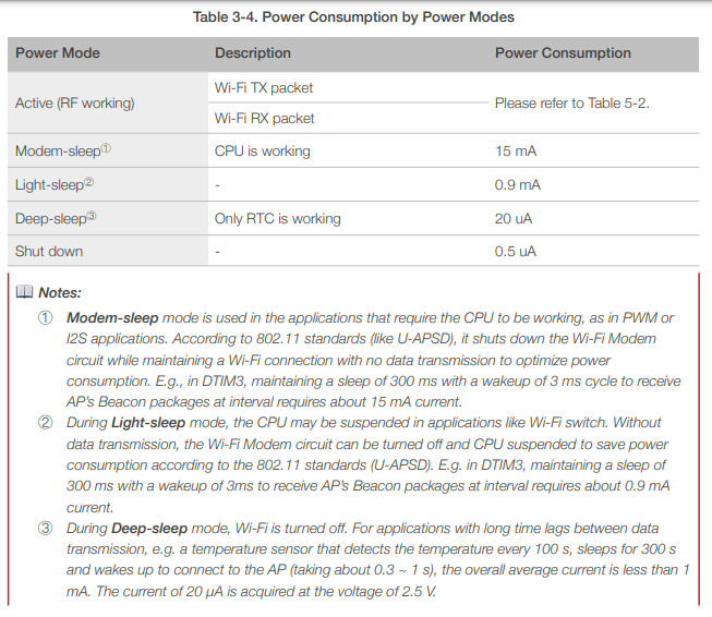
These 5uA is a rather good result - I looked at the ESP8266 datasheet (there is no ESP here, only BK7231N, but I think it's worth comparing) and depending on the sleep mode, the ESP8266 consumes the following currents:
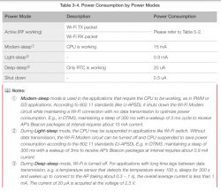
so the manufacturer could actually gain something from this addition of the MCU.
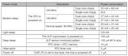
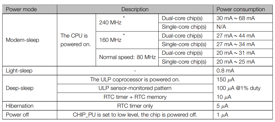
Interestingly, the 5uA result is similar to the ESP32 power consumption in hibernation mode (based on its catalog note):
Of course, the power consumption is also influenced by the power consumption during the operation of the WiFi module - only that it is difficult to judge how much impact it is, because we do not know how often the door will be opened.
The same product also acts as a flood sensor - the system and protocol are identical, the only difference is that a different sensor is soldered.
The sensor itself has already been pre-processed for mine
OpenBeken (I added support for it in my firmware) but it's not the final version, so I'll detail it another time.
Does anyone use this type of sensors and if so, how long does the battery last? Feel free to discuss.


Comments
Or maybe someone noticed this type of sensor, but a smaller one for the CR2032 battery and after BT? [Read more]
I reviewed a sensor that uses a CR1632 that communicates over Zigbee - the Zigbee is generally a bit more energy efficient, but more expensive. Aqara MCCGQ11LM door opening sensor on Zigbee - test,... [Read more]
I do not recommend. The current capacity of the CR2032 drops significantly at low temperatures. It will work in summer, not necessarily in winter. [Read more]
I use several similar sensors: https://obrazki.elektroda.pl/7559075000_1661253121_thumb.jpg https://obrazki.elektroda.pl/9699686800_1661253121_thumb.jpg https://obrazki.elektroda.pl/9107064700_1661253121_thumb.jpg... [Read more]
I have iNODE temperature sensors on BT. I decided to give one outside. On a CR2032 battery, it works very well even in frost. You can see a slight voltage drop when it's very cold, but that doesn't... [Read more]
I have a Zigbee sensor (cc2530). He always died around November / December. After being brought home, he revived. I changed the battery to the little Saft and I have a few years of peace. [Read more]
Maybe something like that Link ? Unfortunately, they are not the cheapest. [Read more]
I have versions with a motion and temperature sensor. I still bought it when it was cheaper. But then when I tested it, it crashed and needed to be restarted. Maybe I will come back to this and check again.... [Read more]
Maybe something wrong with the firmware? In general, there should be no problems with communication, because it is one-way - iNODE only sends statuses. I have several temperature sensors - I set the maximum... [Read more]
I wanted to update the firmware, but on andoid 10 the applications from the website are not running, while on andoid 4.4.2 it works, but the "browse .." button to select the firmware file does not res... [Read more]
As for the TuyaMCU protocol for battery powered devices; such a curiosity; I can see that someone, based on my article about XR809 programming, made a simple demo of this protocol only for this platform: ... [Read more]
Hi. I bought another revision of the water leakage sensor. It contains cb3s and um8005(tuya?) chips. I flashed cb3s with the latest firmware OpenBK. It works, but tuyaMCU needs baud rate 115200. I... [Read more]
Hello. First of all, have you enabled the MQTT broadcast on the connect? https://obrazki.elektroda.pl/6071963900_1671894348_thumb.jpg Flag 10 - [MQTT] Broadcast self state on MQTT c... [Read more]
Thanks for the advice! Now i have enabled flag 10. As a result, the device sends some statuses over the protocol, but not channels 1 and 3. log: Hypothesis: the channel changes before the wifi connects.... [Read more]
Hey, First of all, thank you for the great work. Flashing the sensors worked great with the instructions. This is my first attempt at openbeken. I can also reach the modules via IP address and MQTT.... [Read more]
@klaudi43 https://obrazki.elektroda.pl/6830034000_1673638780_thumb.jpg Please set: Flag 2 - [MQTT] Broadcast self state every N (def: 60) seconds (delay configurable by... [Read more]
Witam, Przede wszystkim dziękuję za szybką informację zwrotną. Dostosowałem ustawienia zgodnie z opisem. Niestety oba kanały wysyłają tylko 0. Zakładam, że jest to związane ze sprzętem. Wydaje się,... [Read more]
Wait a minute, is that your device? There is no TuyaMCU on your board. The TuyaMCU is external microcontroller that is next to the WiFI module: https://obrazki.elektroda.pl/3312860100_1673786748_thumb.jpg... [Read more]
Kupiłem na Ebayu. Numer zn373141_01 jest wydrukowany na opakowaniu. Odpowiada również zdjęciom na AliExpress i jest oferowany jako Tuya / Aubess. [Read more]