logo elektroda
logo elektroda
X
logo elektroda

[BK7231N] 6W RGBCCT E14 LED candle bulb with reassembly (Immax Neo LITE)

leoshusar  4 2217 Cool? (+5)
📢 Listen (AI):

TL;DR

  • An Immax Neo LITE E14 RGBCCT candle bulb built around a BK7231N [CBLC5] module gets disassembled, flashed, and reassembled for local control.
  • Opening the seal, lifting the LED PCB with a hook through the WiFi antenna hole, and supporting the base keeps the AC wires from tearing loose.
  • The bulb is model MK-C37-5LU-20SMD-DLV01, rated 6W, and the UART pads expose BP1658CJ_DAT on P24 and BP1658CJ_CLK on P26.
  • Manual soldering in the tight back space made flashing possible, and a thin string through the WiFi hole helped pull the base module back during reassembly.
Generated by the language model.
Brand: Immax
Model: MK-C37-5LU-20SMD-DLV01
Chip: BK7231N [CBLC5]
Local Vendor: https://www.immax.cz/immax-neo-lite-smart-zar...t-barevna-a-bila-stmivatelna-wifi-c37-p11837/

I've got 3 of these bulbs and wanted to throw Tuya where it belongs. So I bought one more for disassembly, because I didn't know if I'll be able to reassemble it again. I dumped the FW, sent profile request for Cloudcutter and waited. Glad I bought one, because it was impossible to reassemble. If you disassemble it the wrong way.

After a month of waiting, I've lost my patience with Tuya and finally decided to flash it manually. I bought one more for another test and sure enough I found a way to not destroy it.

You will need point tip soldering station and steady hand.

Here is the bulb:


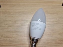
Opening it is quite easy. You can press around the seal and this will loosen it, once you can rotate it, just pop it off.


Now the hard part. You cannot just rip it off, because the neutral AC wire is pushed between the plastic and thread. If you pull it out, you won't be able to reassemble it. Maybe if you soldered a wire directly to the thread from the inside.
The second wire is pushed under the bottom pin - if you rip off this one, it's still possible to put it back, because that pin falls off.

So, what now?
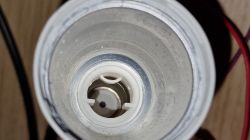
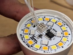
First press on these pins with something to push them down, this will give you more place to not rip off AC wires:

Now get something thin that will act like a hook, I used thin allen key.
Stick it in the WiFi antenna hole:

Now you can pull hard on it to pop the module off. I had to hold it with pliers and pulled really hard.
Be careful to not pull it all the way! Do it just like this:


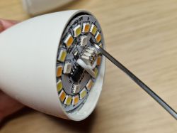
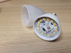
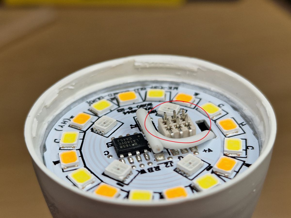
Now stick something like flat screwdriver where the arrow points - between the white PCB and the base module. With the screwdriver you will hold the base module while pulling off the LED PCB:

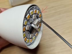
You might also use razor knife to cut the silicone glue on the left side, but sometimes it's not necessary.

Pull it off and the first hard part is done! (yellow circle is where I held my screwdriver - I hope it's understandable)


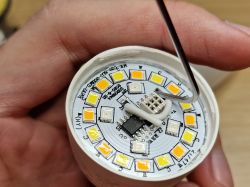
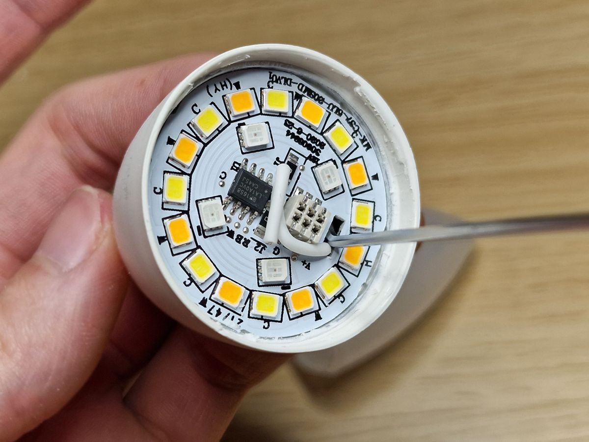
Now second hard part. Soldering!
Since we cannot pull the base out, we need to solder it as it is. Here is where your steady hand comes in.
There is CBLC5 module and UART pins are in the back, in that tight space:
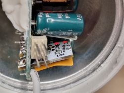
But it's doable!


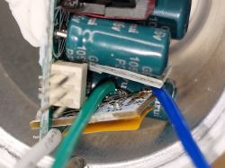
Now I just soldered GND because I was too lazy to find which of those 6 pins is GND:

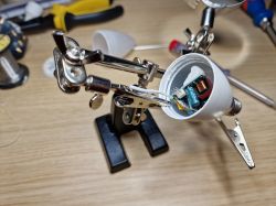
Then I screwed it in my desk lamp (yes, I was also lazy to find VCC :) ), connected UART and flashed. Easy!
Don't connect anything to mains unless you know what you're doing! Or rather even if you know what you are doing.

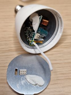
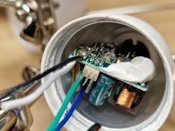
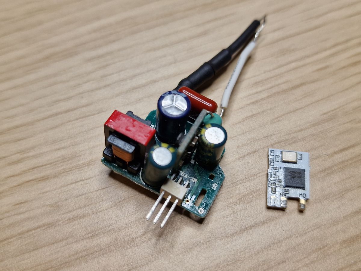
This is what it looks like when you pull it all out, so you don't have to:

And this is where AC wires were - live under the bottom pin and neutral under that "thing" on the top:


Now reassembly. Quite easier process.
I used thin string, put it under / around the Tuya module and pulled it through the WiFi hole:

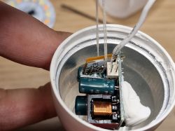
This was so I can pull the base module up with the string and push the LED module on those pins again. If you just try to push on it, the base module will "spring down", because it's just holding on wires and doesn't have any support.

Now just pull the string out and done!


P24: BP1658CJ_DAT
P26: BP1658CJ_CLK

I can finally remove the stupid abandoned Tuya integration from HA.

I hope somebody will find this useful!

About Author
leoshusar wrote 5 posts with rating 5 . Been with us since 2022 year.

Comments

ferbulous 12 Nov 2022 04:57

I applaud your soldering skills, i don’t think i can accomplish the same thing in that tight space As for the AC neutral wire between the plastic and the scree thread. Wouldn’t it be easier... [Read more]

p.kaczmarek2 12 Nov 2022 05:35

Please do not ever connect devices with flashing circuit to mains! This is very dangerous. You could even make a short and blow both device and PC. It is better to keep all tinkering to low voltage only,... [Read more]

leoshusar 12 Nov 2022 15:54

Thank you both! I tried to remove the thread on my first already broken test bulb and didn't manage to remove it without breaking even more. This way was a little harder but less destructive and I'm... [Read more]

p.kaczmarek2 12 Nov 2022 18:20

Everything you need for the Beken (or BL602, or XR809, or W600, etc) "hacking" (as people say) is the USB to UART converter and 3.3V LDO (I am using TC1264-3.3V). Futhermore, you will most likely need... [Read more]

FAQ

TL;DR: 6 W Immax Neo Lite E14 bulbs can be de-Tuya-fied in under 10 min; “Flash by wires is not so hard” [Elektroda, p.kaczmarek2, post #20280390] Follow 3.3 V UART rules and avoid live mains for a 0% PC-fry rate. Why it matters: One careful teardown unlocks full local control without cloud lock-in.

Quick Facts

• Rated power: 6 W RGB+CCT LED, E14 base [Vendor Page]. • Wi-Fi SoC: Beken BK7231N on CBLC5 module [Elektroda, leoshusar, post #20278668] • Flash voltage: 3.3 V UART, current < 200 mA [Elektroda, p.kaczmarek2, post #20281131] • Typical price: 249 CZK ≈ €10 per bulb [Vendor Page]. • Unsafe mains flashing risk: possible PC short, reported by forum moderator [Elektroda, p.kaczmarek2, post #20280390]

What hardware is inside the Immax Neo Lite 6 W E14 bulb?

The driver board hosts a BK7231N Wi-Fi SoC on a CBLC5 module, BP1658CJ LED driver pins (P24 DAT, P26 CLK), and dual AC wires crimped to the E14 shell and center pin [Elektroda, leoshusar, post #20278668]

How do I open the bulb without tearing the neutral wire?

Loosen the plastic-glass seal, rotate the globe, then push the two alignment pins down before hooking the module through the antenna hole. Pull until the PCB clears, but stop before the AC wires stretch [Elektroda, leoshusar, post #20278668]

Which pads are RX, TX, GND, and 3.3 V on the CBLC5?

Looking at the module rear, the six-pad row maps (left→right) to 3.3 V, RX, TX, GND, CEN, RST per Tuya datasheet; the author confirmed only GND visually, flashing successful with those four lines [Elektroda, leoshusar, post #20278668]

What voltage and current are safe for flashing?

Feed 3.3 V regulated, maximum 200 mA. Moderator suggests a TC1264-3.3 LDO between a USB 5 V source and the bulb to avoid over-voltage damage [Elektroda, p.kaczmarek2, post #20281131]

Which tools make the tight-space soldering easier?

  1. Fine-tip soldering iron <0.8 mm.
  2. Thin rosin solder.
  3. USB-to-UART adapter (CP2102/FT232).
  4. 3.3 V LDO regulator.
  5. Hook probe or 1.5 mm Allen key for pulling module [Elektroda, leoshusar, post #20278668]

Can I skip soldering the CEN (BOOT) pin?

Yes. Power-cycle reset works: disconnect 3.3 V, reconnect, then send the firmware. Separate power and UART cables simplify the cycle [Elektroda, p.kaczmarek2, post #20281131]

Why must I avoid flashing while the bulb is on mains power?

Live AC introduces lethal voltage; one short can destroy the bulb and the PC through the USB ground path. The moderator labelled this practice “very dangerous” [Elektroda, p.kaczmarek2, post #20280390]

Quick 3-step method to flash multiple bulbs?

  1. Solder four wires (3.3 V, GND, RX, TX) once.
  2. Use a jig with pogo pins to press onto each opened bulb.
  3. Power-cycle via inline switch, run bk7231-flash script; ~8 bulbs in 30 min reported [Elektroda, p.kaczmarek2, post #20280390]

What alternative firmware can I load after removing Tuya?

Open-BK7231T, Tasmota-BK, and OpenBeken all support RGB+CCT output, MQTT, and Home Assistant autodiscovery on BK7231N chips [OpenBeken Wiki].

Common mistakes that permanently kill the bulb?

  1. Ripping the neutral wire wedged under the thread—impossible to reattach cleanly.
  2. Overheating the tiny UART pads, lifting traces.
  3. Applying 5 V directly—burns the SoC in under 1 s, an irreversible failure [Elektroda, leoshusar, post #20278668]

How do I reassemble the bulb securely?

Thread a thin string under the Wi-Fi module, pull it upward while pressing the LED PCB onto the base pins, then remove the string and snap the globe back on [Elektroda, leoshusar, post #20278668]

Is there a fully non-solder OTA unlock yet?

A Cloudcutter profile was requested but not published as of Nov 2022; manual UART flashing remains the only working route [Elektroda, leoshusar, post #20278668]
Generated by the language model.
%}